
LM2672M-12
SIMPLE SWITCHER® 12V, 1A Step-Down Voltage Regulator
LM2672 SIMPLE SWITCHER® Power Converter High Efficiency 1-A Step-Down Voltage Regulator with Features
1 Features
1• Efficiency up to 96%
• Available in 8-Pin SOIC and PDIP Packages
• Requires only 5 External Components
• 3.3-V, 5-V, 12-V, and Adjustable Output Versions
• Adjustable Version Output Voltage Range: 1.21 V to 37 V
• ±1.5% Maximum Output Voltage Tolerance Over Line and Load Conditions
• Specified 1-A Output Load Current
• Wide Input Voltage Range: 8 V to 40 V
• 260-kHz Fixed Frequency Internal Oscillator
• TTL Shutdown Capability, Low Power Standby Mode
• Soft-Start and Frequency Synchronization
• Thermal Shutdown and Current Limit Protection
2 Applications
Simple High Efficiency (>90%) Step-Down (Buck) Regulator
• Efficient Preregulator for Linear Regulators
3 Description
The LM2672 series of regulators are monolithic integrated DC-DC converter built with a LMDMOS process. These regulators provide all the active functions for a step-down (buck) switching regulator, capable of driving a 1-A load current with excellent line and load regulation. These devices are available in fixed output voltages of 3.3 V, 5 V, 12 V, and an adjustable output version.
Requiring a minimum number of external components, these regulators are simple to use and include patented internal frequency compensation, fixed frequency oscillator, external shutdown, softstart, and frequency synchronization.
The LM2672 series operates at a switching frequency of 260 kHz, thus allowing smaller sized filter components than what is required with lower frequency switching regulators. Because of its very high efficiency (>90%), the copper traces on the printed-circuit board are the only heat sinking required.
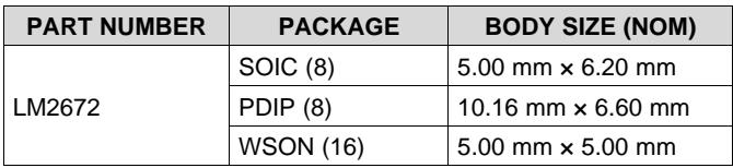
Device Information(1)
| PART NUMBER | PACKAGE | BODY SIZE (NOM) |
| LM2672 | SOIC (8) | 5.00 mm × 6.20 mm |
| PDIP (8) | 10.16 mm × 6.60 mm | |
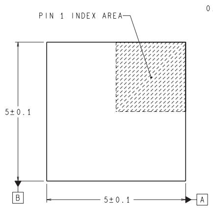
| WSON (16) | 5.00 mm × 5.00 mm |
(1) For all available packages, see the orderable addendum at the end of the data sheet.

Fixed output voltage versions
Copyright © 2016, Texas Instruments Incorporated
Table of Contents
1 Features.... 1
2 Applications.... 1
3 Description.... 1
4 Revision History.... 2
5 Description (continued).... 3
6 Pin Configuration and Functions.... 3
7 Specifications.... 4
7.1 Absolute Maximum Ratings.... 4
7.2 ESD Ratings.... 4
7.3 Recommended Operating Conditions.... 4
7.4 Thermal Information.... 4
7.5 Electrical Characteristics – 3.3 V.... 5
7.6 Electrical Characteristics – 5 V.... 5
7.7 Electrical Characteristics – 12 V.... 5
7.8 Electrical Characteristics – Adjustable.... 6
7.9 Electrical Characteristics – All Output Voltage Versions.... 6
7.10 Typical Characteristics.... 7
7.11 Typical Characteristics – Fixed Output Voltage Versions.... 9
8 Parameter Measurement Information.... 10
9 Detailed Description.... 11
9.1 Overview.... 11
9.2 Functional Block Diagram.... 11
9.3 Feature Description.... 11
9.4 Device Functional Modes.... 12
10 Application and Implementation.... 13
10.1 Application Information.... 13
10.2 Typical Applications.... 14
11 Power Supply Recommendations.... 25
12 Layout.... 25
12.1 Layout Guidelines.... 25
12.2 Layout Examples.... 25
13 Device and Documentation Support.... 27
13.1 Documentation Support.... 27
13.2 Receiving Notification of Documentation Updates.... 27
13.3 Community Resources.... 27
13.4 Trademarks.... 27
13.5 Electrostatic Discharge Caution.... 27
13.6 Glossary.... 27
14 Mechanical, Packaging, and Orderable Information.... 27
14.1 DAP (WSON Package).... 27
4 Revision History
NOTE: Page numbers for previous revisions may differ from page numbers in the current version.
Changes from Revision K (April 2013) to Revision L
Page
Added ESD Ratings table, Feature Description section, Device Functional Modes, Application and Implementation section, Power Supply Recommendations section, Layout section, Device and Documentation Support section, and Mechanical, Packaging, and Orderable Information section .... 1
• Removed all references to Computer Design Software LM267X Made Simple (Version 6.0)......... ................
Changes from Revision J (April 2013) to Revision K
- Changed layout of National Data Sheet to TI format .... 1
5 Description (continued)
A family of standard inductors for use with the LM2672 are available from several different manufacturers. This feature greatly simplifies the design of switch-mode power supplies using these advanced ICs. Also included in the datasheet are selector guides for diodes and capacitors designed to work in switch-mode power supplies.
Other features include ±1.5%-tolerance on output voltage within specified input voltages and output load conditions, and ±10% on the oscillator frequency. External shutdown is included, featuring typically 50 $\mu { \sf A }$ standby current. The output switch includes current limiting, as well as thermal shutdown for full protection under fault conditions.
6 Pin Configuration and Functions

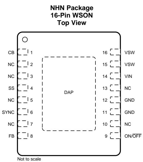
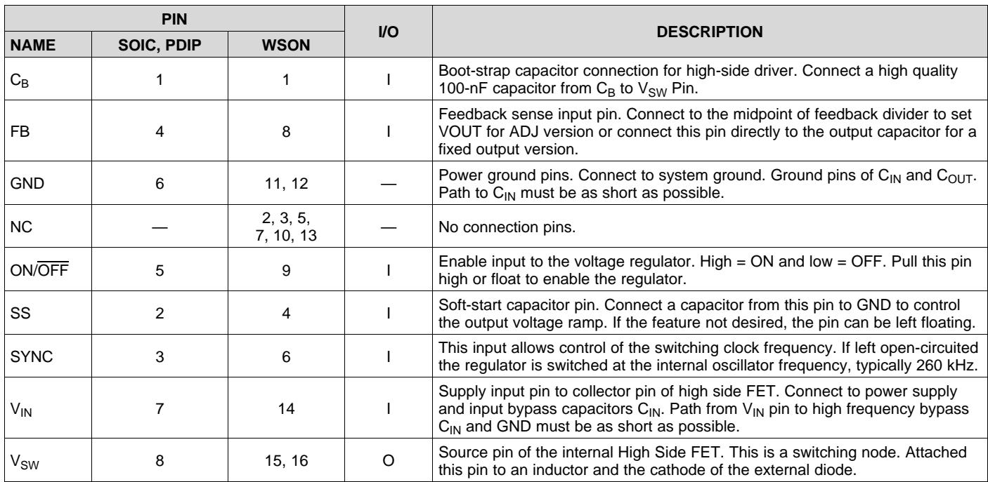
Pin Functions
| PIN | I/O | DESCRIPTION | ||
| NAME | SOIC, PDIP | WSON | ||
| $C_B$ | 1 | 1 | I | Boot-strap capacitor connection for high-side driver. Connect a high quality 100-nF capacitor from $C_B$ to $V_{SW}$ Pin. |
| FB | 4 | 8 | I | Feedback sense input pin. Connect to the midpoint of feedback divider to set VOUT for ADJ version or connect this pin directly to the output capacitor for a fixed output version. |
| GND | 6 | 11, 12 | — | Power ground pins. Connect to system ground. Ground pins of $C_{IN}$ and $C_{OUT}$ . Path to $C_{IN}$ must be as short as possible. |
| NC | — | 2, 3, 5, 7, 10, 13 | — | No connection pins. |
| ON/OFF | 5 | 9 | I | Enable input to the voltage regulator. High = ON and low = OFF. Pull this pin high or float to enable the regulator. |
| SS | 2 | 4 | I | Soft-start capacitor pin. Connect a capacitor from this pin to GND to control the output voltage ramp. If the feature not desired, the pin can be left floating. |
| SYNC | 3 | 6 | I | This input allows control of the switching clock frequency. If left open-circuited the regulator is switched at the internal oscillator frequency, typically 260 kHz. |
| $V_{IN}$ | 7 | 14 | I | Supply input pin to collector pin of high side FET. Connect to power supply and input bypass capacitors $C_{IN}$ . Path from $V_{IN}$ pin to high frequency bypass $C_{IN}$ and GND must be as short as possible. |
| $V_{SW}$ | 8 | 15, 16 | O | Source pin of the internal High Side FET. This is a switching node. Attached this pin to an inductor and the cathode of the external diode. |
7 Specifications
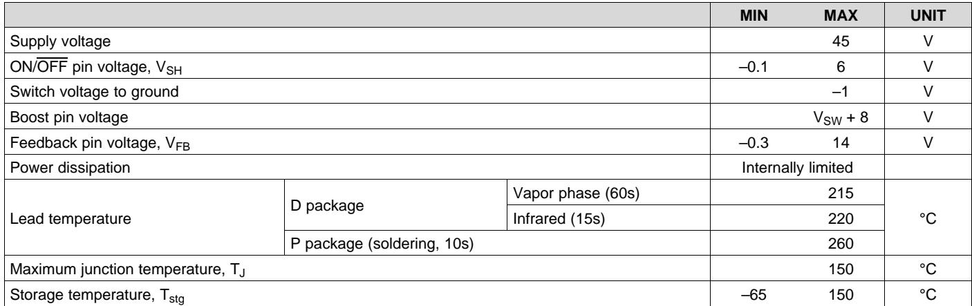
7.1 Absolute Maximum Ratings
over recommended operating junction temperature range of $\scriptscriptstyle - 4 0 ^ { \circ } \mathsf { C }$ to $1 2 5 ^ { \circ } \mathrm { C }$ (unless otherwise noted)(1)
| MIN | MAX | UNIT | |||
| Supply voltage | 45 | V | |||
| ON/OFF pin voltage, VSH | -0.1 | 6 | V | ||
| Switch voltage to ground | -1 | V | |||
| Boost pin voltage | VSW+8 | V | |||
| Feedback pin voltage, VFB | -0.3 | 14 | V | ||
| Power dissipation | Internally limited | ||||
| Lead temperature | D package | Vapor phase (60s) | 215 | °C | |
| Infrared (15s) | 220 | ||||
| P package (soldering, 10s) | 260 | ||||
| Maximum junction temperature, TJ | 150 | °C | |||
| Storage temperature, Tstg | -65 | 150 | °C | ||
(1) Stresses beyond those listed under Absolute Maximum Ratings may cause permanent damage to the device. These are stress ratings only, which do not imply functional operation of the device at these or any other conditions beyond those indicated under Recommended Operating Conditions. Exposure to absolute-maximum-rated conditions for extended periods may affect device reliability.
7.2 ESD Ratings
| VALUE | UNIT | |||
| $V_{(ESD)}$ | Electrostatic discharge | Human-body model (HBM), per ANSI/ESDA/JEDEC JS-001 $^{(1)}$ | ±2000 | V |
(1) JEDEC document JEP155 states that 500-V HBM allows safe manufacturing with a standard ESD control process.
7.3 Recommended Operating Conditions
over operating free-air temperature range (unless otherwise noted)
| MIN | MAX | UNIT | ||
| Supply voltage | 6.5 | 40 | V | |
| $T_J$ | Operating junction temperature | -40 | 125 | °C |
7.4 Thermal Information
| THERMAL METRIC(1)(2) | LM2672 | UNIT | |||
| D (SOIC) | P (PDIP) | WSON (NHN) | |||
| 8 PINS | 8 PINS | 16 PINS | |||
| $R_{\theta JA}$ | Junction-to-ambient thermal resistance | 105 | 95 | — | °C/W |
| $R_{\theta JC(top)}$ | Junction-to-case (top) thermal resistance | — | — | — | °C/W |
| $R_{\theta JB}$ | Junction-to-board thermal resistance | — | — | — | °C/W |
| $\psi_{JT}$ | Junction-to-top characterization parameter | — | — | — | °C/W |
| $\psi_{JB}$ | Junction-to-board characterization parameter | — | — | — | °C/W |
| $R_{\theta JC(bot)}$ | Junction-to-case (bottom) thermal resistance | — | — | — | °C/W |
(1) For more information about traditional and new thermal metrics, see the Semiconductor and IC Package Thermal Metrics application report.
(2) Thermal resistances were simulated on 4-layer JEDEC board.
7.5 Electrical Characteristics – 3.3 V
${ \sf T } _ { \mathrm { J } } = 2 5 ^ { \circ } { \sf C }$ (unless otherwise noted; see Figure 19)(1)
| PARAMETER | TEST CONDITIONS | MIN(2) | TYP(3) | MAX(2) | UNIT | ||
| $V_{OUT}$ | Output voltage | $V_{IN}=8 V to 40 V, I_{LOAD}=20 mA to 1 A$ | $T_J=25°C$ | 3.251 | 3.3 | 3.35 | V |
| $T_J=-40°C to 125°C$ | 3.201 | 3.399 | |||||
| $V_{IN}=6.5 V to 40 V, I_{LOAD}=20 mA to 500 mA$ | $T_J=25°C$ | 3.35 | 3.3 | 3.35 | |||
| $T_J=-40°C to 125°C$ | 3.201 | 3.399 | |||||
| η | Efficiency | $V_{IN}=12 V, I_{LOAD}=1 A$ | 86% | ||||
(1) External components such as the catch diode, inductor, input and output capacitors, and voltage programming resistors can affect switching regulator performance. When the LM2672 is used as shown in Figure 19 test circuits, system performance is as specified by the system parameters section of Electrical Characteristics.
(2) All limits specified at room temperature and at temperature extremes. All room temperature limits are 100% production tested. All limits at temperature extremes are specified through correlation using standard Statistical Quality Control (SQC) methods. All limits are used to calculate Average Outgoing Quality Level (AOQL).
(3) Typical numbers are at 25°C and represent the most likely norm.
7.6 Electrical Characteristics – 5 V
T = 25°C (unless otherwise noted; see Figure 19)(1)
| PARAMETER | TEST CONDITIONS | MIN(2) | TYP(3) | MAX(2) | UNIT | ||
| $V_{OUT}$ | Output voltage | $V_{IN}=8 V to 40 V, I_{LOAD}=20 mA to 1 A$ | $T_J=25°C$ | 4.925 | 5 | 5.075 | V |
| $T_J=-40°C to 125°C$ | 4.85 | 5.15 | |||||
| $V_{IN}=6.5 V to 40 V, I_{LOAD}=20 mA to 500 mA$ | $T_J=25°C$ | 4.925 | 5 | 5.075 | |||
| $T_J=-40°C to 125°C$ | 4.85 | 5.15 | |||||
| η | Efficiency | $V_{IN}=12 V, I_{LOAD}=1 A$ | 90% | ||||
(1) External components such as the catch diode, inductor, input and output capacitors, and voltage programming resistors can affect switching regulator performance. When the LM2672 is used as shown in Figure 19 test circuits, system performance is as specified by the system parameters section of Electrical Characteristics.
(2) All limits specified at room temperature and at temperature extremes. All room temperature limits are 100% production tested. All limits at temperature extremes are specified through correlation using standard Statistical Quality Control (SQC) methods. All limits are used to calculate Average Outgoing Quality Level (AOQL).
(3) Typical numbers are at 25°C and represent the most likely norm.
7.7 Electrical Characteristics – 12 V
${ \sf T } _ { \mathrm { J } } = 2 5 ^ { \circ } { \sf C }$ (unless otherwise noted; see Figure 19)(1)
| PARAMETER | TEST CONDITIONS | MIN(2) | TYP(3) | MAX(2) | UNIT | ||
| $V_{OUT}$ | Output voltage | $V_{IN} = 15 \text{ V to } 40 \text{ V, } I_{LOAD} = 20 \text{ mA to } 1 \text{ A}$ | $T_J = 25°C$ | 11.82 | 12 | 12.18 | V |
| $T_J = -40°C \text{ to } 125°C$ | 11.64 | 12.36 | |||||
| $\eta$ | Efficiency | $V_{IN} = 24 \text{ V, } I_{LOAD} = 1 \text{ A}$ | 94% | ||||
(1) External components such as the catch diode, inductor, input and output capacitors, and voltage programming resistors can affect switching regulator performance. When the LM2672 is used as shown in Figure 19 test circuits, system performance is as specified by the system parameters section of Electrical Characteristics.
(2) All limits specified at room temperature and at temperature extremes. All room temperature limits are 100% production tested. All limits at temperature extremes are specified through correlation using standard Statistical Quality Control (SQC) methods. All limits are used to calculate Average Outgoing Quality Level (AOQL).
(3) Typical numbers are at 25°C and represent the most likely norm.
7.8 Electrical Characteristics – Adjustable
${ \sf T } _ { \mathrm { J } } = 2 5 ^ { \circ } { \sf C }$ (unless otherwise noted; see Figure 19)(1)
| PARAMETER | TEST CONDITIONS | MIN(2) | TYP(3) | MAX(2) | UNIT | ||
| $V_{FB}$ | Feedback voltage | $V_{IN}=8 V to 40 V, I_{LOAD}=20 mA to 1 A, V_{OUT}programmed for 5 V (see Figure 19) | \(T_J=25°C$ | 1.192 | 1.21 | 1.228 | V |
| $T_J=-40°C to 125°C$ | 1.174 | 1.246 | |||||
| $V_{IN}=6.5 V to 40 V, I_{LOAD}=20 mA to 500 mA, V_{OUT}programmed for 5 V (see Figure 19) | \(T_J=25°C$ | 1.192 | 1.21 | 1.228 | |||
| $T_J=-40°C to 125°C$ | 1.174 | 1.246 | |||||
| η | Efficiency | $V_{IN}=12 V, I_{LOAD}=1 A$ | 90% | ||||
(1) External components such as the catch diode, inductor, input and output capacitors, and voltage programming resistors can affect switching regulator performance. When the LM2672 is used as shown in Figure 19 test circuits, system performance is as specified by the system parameters section of Electrical Characteristics.
(2) All limits specified at room temperature and at temperature extremes. All room temperature limits are 100% production tested. All limits at temperature extremes are specified through correlation using standard Statistical Quality Control (SQC) methods. All limits are used to calculate Average Outgoing Quality Level (AOQL).
(3) Typical numbers are at $2 5 ^ { \circ } \mathrm { C }$ and represent the most likely norm.
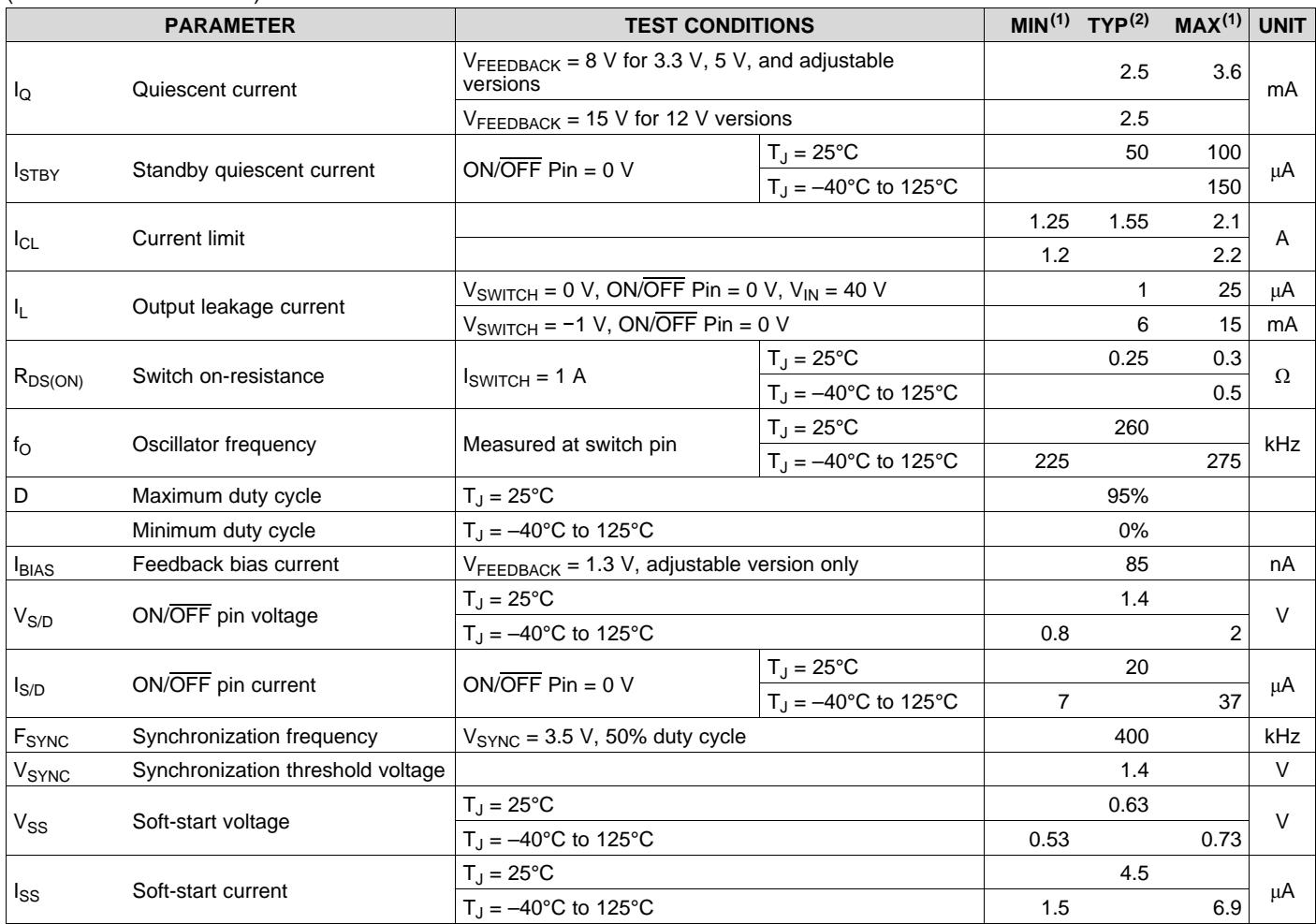
7.9 Electrical Characteristics – All Output Voltage Versions
$\mathsf { T } _ { \mathsf { J } } = 2 5 ^ { \circ } \mathsf { C } , \mathsf { V } _ { \mathsf { I N } } = 1 2 \mathsf { V }$ for the 3.3 V, 5 V, and Adjustable versions and $\mathsf { V } _ { \mathsf { I N } } = 2 4 \mathsf { V }$ for the 12V version, and $\mathsf { I } _ { \mathsf { L O A D } } = 1 0 0 \mathsf { m A }$ (unless otherwise noted)
| PARAMETER | TEST CONDITIONS | MIN(1) | TYP(2) | MAX(1) | UNIT | ||
| $I_Q$ | Quiescent current | $V_{FEEDBACK}=8 V for 3.3 V, 5 V, and adjustable versions | 2.5 | 3.6 | mA | ||
| \(V_{FEEDBACK}=15 V for 12 V versions | 2.5 | ||||||
| \(I_{STBY}$ | Standby quiescent current | ON/OFF Pin = 0 V | $T_J=25°C$ | 50 | 100 | μA | |
| $T_J=-40°C to 125°C$ | 150 | ||||||
| $I_{CL}$ | Current limit | 1.25 | 1.55 | 2.1 | A | ||
| 1.2 | 2.2 | ||||||
| $I_L$ | Output leakage current | $V_{SWITCH}=0 V, ON/OFF Pin=0 V, V_{IN}=40 V$ | 1 | 25 | μA | ||
| $V_{SWITCH}=-1 V, ON/OFF Pin=0 V$ | 6 | 15 | mA | ||||
| $R_{DS(ON)}$ | Switch on-resistance | $I_{SWITCH}=1 A$ | $T_J=25°C$ | 0.25 | 0.3 | Ω | |
| $T_J=-40°C to 125°C$ | 0.5 | ||||||
| $f_O$ | Oscillator frequency | Measured at switch pin | $T_J=25°C$ | 260 | kHz | ||
| $T_J=-40°C to 125°C$ | 225 | 275 | |||||
| D | Maximum duty cycle | $T_J=25°C$ | 95% | ||||
| Minimum duty cycle | $T_J=-40°C to 125°C$ | 0% | |||||
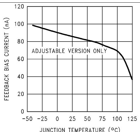
| $I_{BIAS}$ | Feedback bias current | $V_{FEEDBACK}=1.3 V, adjustable version only$ | 85 | nA | |||
| $V_{S/D}$ | ON/OFF pin voltage | $T_J=25°C$ | 1.4 | V | |||
| $T_J=-40°C to 125°C$ | 0.8 | 2 | |||||
| $I_{S/D}$ | ON/OFF pin current | ON/OFF Pin = 0 V | $T_J=25°C$ | 20 | μA | ||
| $T_J=-40°C to 125°C$ | 7 | 37 | |||||
| $F_{SYNC}$ | Synchronization frequency | $V_{SYNC}=3.5 V, 50\% duty cycle$ | 400 | kHz | |||
| $V_{SYNC}$ | Synchronization threshold voltage | 1.4 | V | ||||
| $V_{SS}$ | Soft-start voltage | $T_J=25°C$ | 0.63 | V | |||
| $T_J=-40°C to 125°C$ | 0.53 | 0.73 | |||||
| $I_{SS}$ | Soft-start current | $T_J=25°C$ | 4.5 | μA | |||
| $T_J=-40°C to 125°C$ | 1.5 | 6.9 | |||||
(1) All limits specified at room temperature and at temperature extremes. All room temperature limits are 100% production tested. All limits at temperature extremes are specified through correlation using standard Statistical Quality Control (SQC) methods. All limits are used to calculate Average Outgoing Quality Level (AOQL).
(2) Typical numbers are at 25°C and represent the most likely norm.
7.10 Typical Characteristics
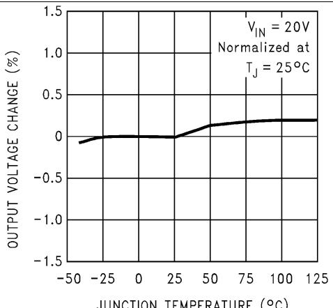
JUNCTION TEMPERATURE (°C)
Figure 1. Normalized Output Voltage
INPUT VOLTAGE (V)
Figure 3. Efficiency
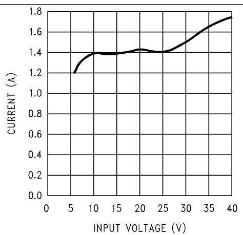
Figure 5. Switch Current Limit
JUNCTION TEMPERATURE (°C)
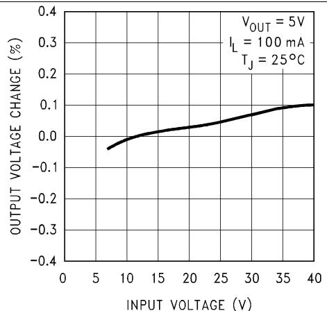
Figure 2. Line Regulation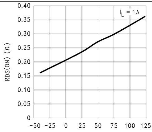
JUNCTION TEMPERATURE (°C)
Figure 4. Drain-to-Source Resistance
JUNCTION TEMPERATURE (°C)
Figure 6. Operating Quiescent Current
Typical Characteristics (continued)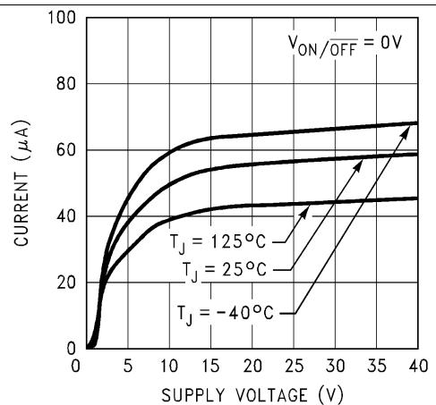
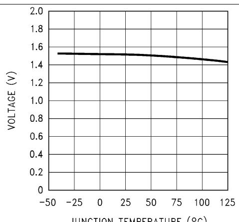
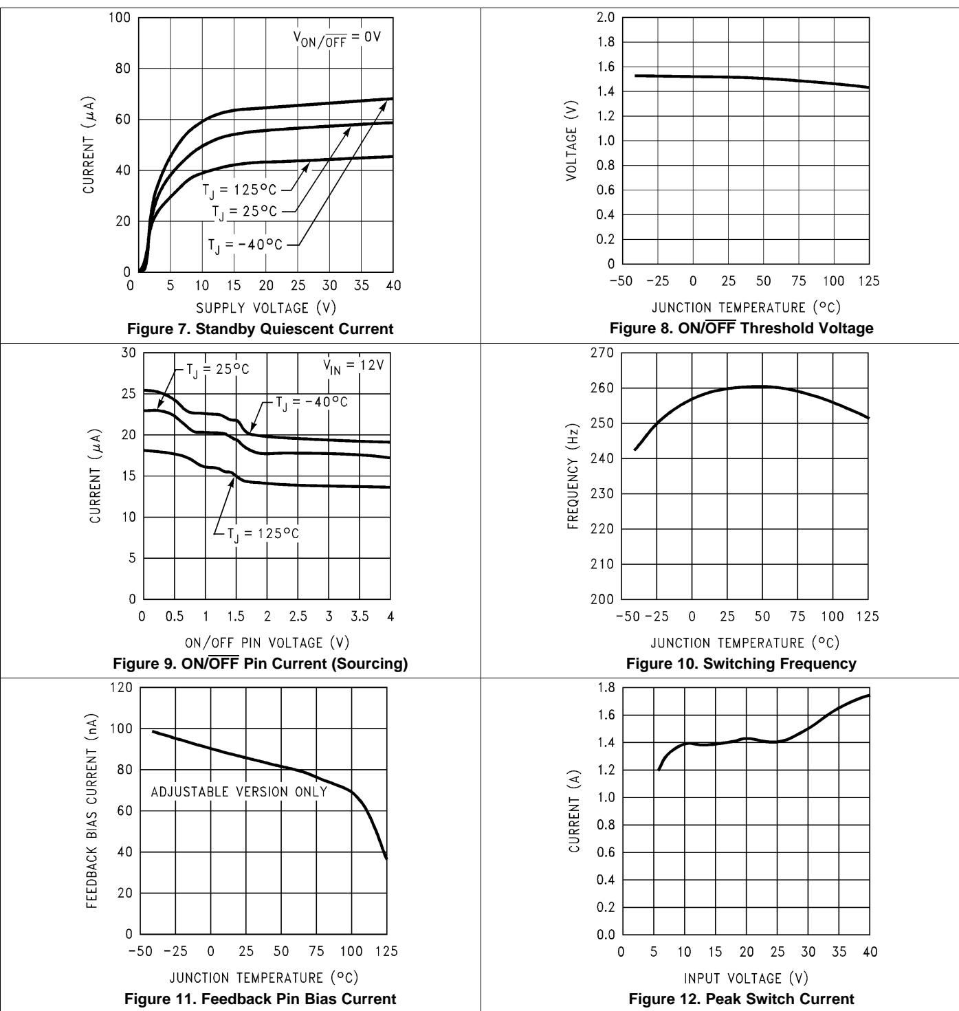
| Figure 7. Standby Quiescent Current | Figure 8. ON/OFF Threshold Voltage |
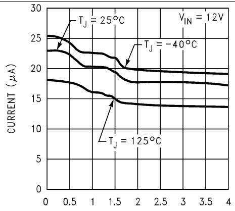
| Figure 9. ON/OFF Pin Current (Sourcing) | Figure 10. Switching Frequency |
| Figure 11. Feedback Pin Bias Current | Figure 12. Peak Switch Current |

Output ripple voltage, 20 mV/div AC-coupled
Inductor current, 0.5 A/div
V pin voltage, 10 V/div Inductor current, 0.5 A/div Output ripple voltage, 20 mV/div AC-coupled
Typical Characteristics (continued)
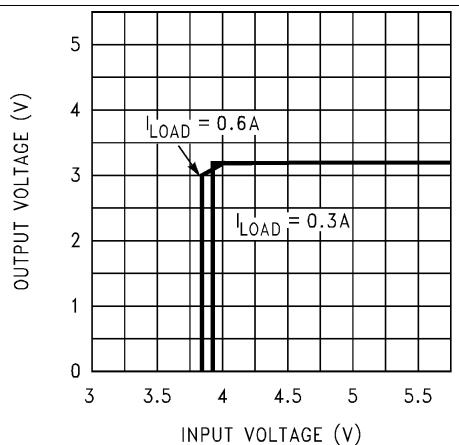
Figure 13. Dropout Voltage, 3.3-V Option

Figure 14. Dropout Voltage, 5-V Option
7.11 Typical Characteristics – Fixed Output Voltage Versions see Figure 19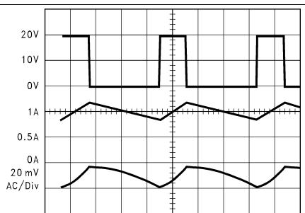
V pin voltage, 10 V/div
$$
V _ {I N} = 2 0 \mathrm{V}, V _ {O U T} = 5 \mathrm{V},
$$
$$
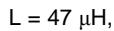
I _ {L O A D} = 1 \mathrm{A}, L = 4 7 \mu \mathrm{H},
$$
COUTESR = 50 mΩ
$$
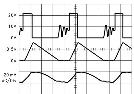
V _ {I N} = 2 0 \mathrm{V}, V _ {O U T} = 5 \mathrm{V},
$$
ILOAD = 300 mA, L = 15 μH,
COUT = 68 μF (2×),
COUTESR = 25 mΩ
Figure 15. Continuous Mode Switching Waveforms, Horizontal Time Base: 1 μs/div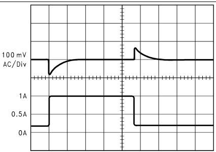
Figure 16. Discontinuous Mode Switching Waveforms, Horizontal Time Base: 1 μs/div
Output voltage,
100 mV/div, AC-coupled
$$
V _ {I N} = 2 0 \mathrm{V}, V _ {O U T} = 5 \mathrm{V},
$$
Load current: 200 mA to 1 A load pulse
$$
I _ {L O A D} = 1 \mathrm{A}, L = 4 7 \mu \mathrm{H},
$$
$$
C _ {O U T} = 6 8 \mu F,
$$
COUTESR = 50 mΩ
Figure 17. Load Transient Response for Continuous Mode, Horizontal Time Base: 50 μs/div

Output voltage,
$$
V _ {I N} = 2 0 \mathrm{V}, V _ {O U T} = 5 \mathrm{V},
$$
100 mV/div, AC-coupled
$$
\mathrm{L} = 4 7 \mu \mathrm{H},
$$
Load current: 100 mA to 300 mA load pulse
$$
\mathrm{C} _ {\text { OUT }} = 6 8 \mu \mathrm{F},
$$
COUTESR = 50 mΩ
Figure 18. Load Transient Response for Discontinuous Mode, Horizontal Time Base: 200 μs/div
8 Parameter Measurement Information

Copyright © 2016, Texas Instruments Incorporated
CIN = 22-μF, 50-V Tantalum Sprague 199D Series
COUT = 47-μF, 25-V Tantalum Sprague 595D Series
D1 = 3.3-A, 50-V Schottky Rectifier, IR 30WQ05F
L1 = 68-μH Sumida #RCR110D-680L
$\mathsf { C } _ { \mathsf { B } } = 0 . 0 1 \mathsf { - \mu F }$ , 50-V ceramic
Figure 19. Standard Test Circuits and Layout Guides, Fixed Output Voltage Versions
9 Detailed Description
9.1 Overview
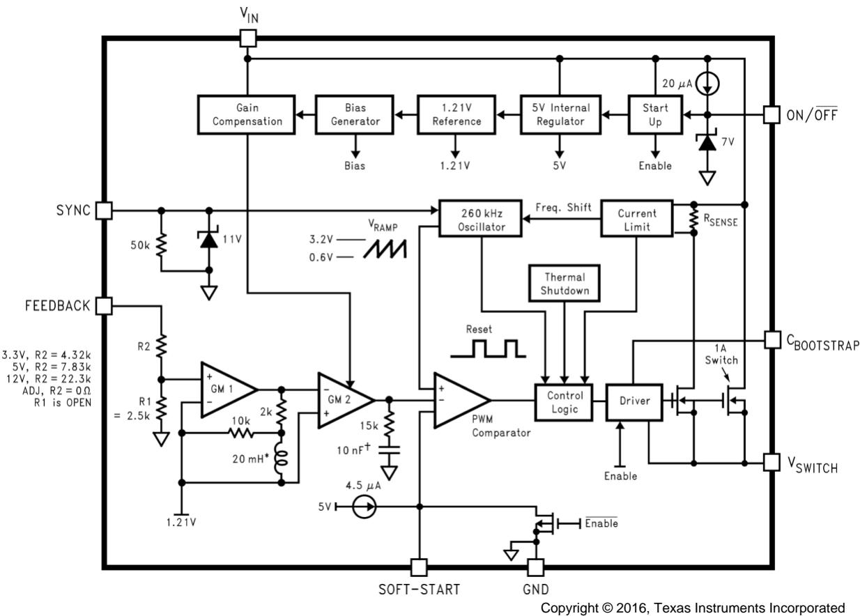
The LM2672 provides all of the active functions required for a step-down (buck) switching regulator. The internal power switch is a DMOS power MOSFET to provide power supply designs with high current capability, up to 1 A, and highly efficient operation.
The LM2672 is part of the SIMPLE SWITCHER® family of power converters. A complete design uses a minimum number of external components, which have been pre-determined from a variety of manufacturers. Using either this data sheet or TI's WEBENCH® design tool, a complete switching power supply can be designed quickly. Refer to LM2670 SIMPLE SWITCHER® High Efficiency 3A Step-Down Voltage Regulator with Sync for additional application information.
9.2 Functional Block Diagram
9.3 Feature Description
9.3.1 Switch Output
This is the output of a power MOSFET switch connected directly to the input voltage. The switch provides energy to an inductor, an output capacitor and the load circuitry under control of an internal pulse-width-modulator (PWM). The PWM controller is internally clocked by a fixed 260-kHz oscillator. In a standard step-down application the duty cycle (time ON or time OFF) of the power switch is proportional to the ratio of the power supply output voltage to the input voltage. The voltage on the $\mathsf { V } _ { \mathsf { S W } }$ pin cycles between $\mathsf { V } _ { \mathsf { i n } }$ (switch ON) and below ground by the voltage drop of the external Schottky diode (switch OFF).
Feature Description (continued)
9.3.2 C Boost
A capacitor must be connected from the $C _ { \mathsf { B } }$ pin to the $\mathsf { V } _ { \mathsf { S W } }$ pin. This capacitor boosts the gate drive to the internal MOSFET above $\mathsf { V } _ { \mathsf { i n } }$ to fully turn it ON. This minimizes conduction losses in the power switch to maintain high efficiency. The recommended value for C Boost is 0.01 $\mu \mathsf { F }$
9.3.3 SYNC
This input allows control of the switching clock frequency. If left open-circuited the regulator is switched at the internal oscillator frequency, typically 260 kHz. An external clock can be used to force the switching frequency and thereby control the output ripple frequency of the regulator. This capability provides for consistent filtering of the output ripple from system to system as well as precise frequency spectrum positioning of the ripple frequency which is often desired in communications and radio applications. This external frequency must be greater than the LM2672 internal oscillator frequency, which could be as high as 275 kHz, to prevent an erroneous reset of the internal ramp oscillator and PWM control of the power switch. The ramp oscillator is reset on the positive going edge of the sync input signal. TI recommends that the external TTL or CMOS compatible clock (between 0 V and a level greater than 3 V) be AC-coupled to the SYNC pin through a 100-pF capacitor and a 1-kΩ resistor to ground.
When the SYNC function is used, current limit frequency foldback is not active. Therefore, the device may not be fully protected against extreme output short circuit conditions.
9.3.4 Feedback
This is the input to a two-stage high gain amplifier, which drives the PWM controller. Connect the FB pin directly to the output for proper regulation. For the fixed output devices (3.3-V, 5-V, and 12-V outputs), a direct wire connection to the output is all that is required as internal gain setting resistors are provided inside the LM2672. For the adjustable output version two external resistors are required to set the DC output voltage. For stable operation of the power supply, it is important to prevent coupling of any inductor flux to the feedback input.
9.4 Device Functional Modes
9.4.1 ON/OFF
This input provides an electrical ON/OFF control of the power supply. Connecting this pin to ground or to any voltage less than 1.4 V completely turns OFF the regulator. The current drain from the input supply when OFF is only ${ \bar { 5 } } 0 ~ \mu \mathsf { A } .$ . The ON/OFF input has an internal pullup current source of approximately 20 μA and a protection clamp Zener diode of 7 V to ground. When electrically driving the ON/OFF pin the high voltage level for the ON condition must not exceed the 6-V absolute maximum limit. When ON/OFF control is not required this pin must be left open.
9.4.2 Shutdown Mode
The ON/OFF pin provides electrical ON and OFF control for the LM2671. When the voltage of this pin is lower than 1.4 $\vee ,$ the device is shutdown mode. The typical standby current in this mode is 50 $\mu { \sf A } ,$
9.4.3 Active Mode
When the voltage of the ON/OFF pin is higher than 1.4 V, the device starts switching and the output voltage rises until it reaches a normal regulation voltage.
10 Application and Implementation
NOTE
Information in the following applications sections is not part of the TI component specification, and TI does not warrant its accuracy or completeness. TI’s customers are responsible for determining suitability of components for their purposes. Customers should validate and test their design implementation to confirm system functionality.
10.1 Application Information
The LM2672 is a step-down DC-DC regulator. It is typically used to convert a higher DC voltage to a lower DC voltage with a maximum output current of 1 A. The following design procedure can be used to select components for the LM2672.
When the output voltage is greater than approximately 6 V, and the duty cycle at minimum input voltage is greater than approximately 50%, the designer must exercise caution in selection of the output filter components. When an application designed to these specific operating conditions is subjected to a current limit fault condition, it may be possible to observe a large hysteresis in the current limit. This can affect the output voltage of the device until the load current is reduced sufficiently to allow the current limit protection circuit to reset itself.
Under current limiting conditions, the LM267x is designed to respond in the following manner:
At the moment when the inductor current reaches the current limit threshold, the ON-pulse is immediately terminated. This happens for any application condition.
However, the current limit block is also designed to momentarily reduce the duty cycle to below 50% to avoid subharmonic oscillations, which could cause the inductor to saturate.
Thereafter, once the inductor current falls below the current limit threshold, there is a small relaxation time during which the duty cycle progressively rises back above 50% to the value required to achieve regulation.
If the output capacitance is sufficiently large, it may be possible that as the output tries to recover, the output capacitor charging current is large enough to repeatedly re-trigger the current limit circuit before the output has fully settled. This condition is exacerbated with higher output voltage settings because the energy requirement of the output capacitor varies as the square of the output voltage (½ CV2), thus requiring an increased charging current. A simple test to determine if this condition might exist for a suspect application is to apply a short circuit across the output of the converter, and then remove the shorted output condition. In an application with properly selected external components, the output recovers smoothly. Practical values of external components that have been experimentally found to work well under these specific operating conditions are COUT = 47 µF, L = 22 µH. Note that even with these components, for a device’s current limit of ICLIM, the maximum load current under which the possibility of the large current limit hysteresis can be minimized is I /2. For example, if the input is 24 V and the set output voltage is 18 V, then for a desired maximum current of 1.5 A, the current limit of the chosen switcher must be confirmed to be at least 3 A. Under extreme overcurrent or short-circuit conditions, the LM267X employs frequency foldback in addition to the current limit. If the cycle-by-cycle inductor current increases above the current limit threshold (due to short circuit or inductor saturation for example) the switching frequency is automatically reduced to protect the IC. Frequency below 100 KHz is typical for an extreme shortcircuit condition.
10.2 Typical Applications
10.2.1 Typical Application for Fixed Output Voltage Versions
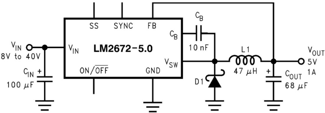
Copyright © 2016, Texas Instruments Incorporated
L1 = 68-μH Sumida #RCR110D-680L
CB = 0.01-μF, 50-V Ceramic
Figure 20. Fixed Output Voltage Typical Application
10.2.1.1 Design Requirements
Table 1 lists the design requirements for the fixed output voltage application.
Table 1. Fixed Output Voltage Application Parameters
| PARAMETER | VALUE |
| Regulated output voltage (3.3 V, 5 V, or 12 V), $V_{OUT}$ | 5 V |
| Maximum DC input voltage, $V_{IN}$ (max) | 12 V |
| Maximum load current, $I_{LOAD}$ (max) | 1 A |
10.2.1.2 Detailed Design Procedure
10.2.1.2.1 Inductor Selection (L1)
First, select the correct inductor value selection guide from Figure 23, Figure 24, or Figure 25 (output voltages of 3.3-V, 5-V, or 12-V respectively). For all other voltages, see the design procedure for the adjustable version. Use the inductor selection guide for the 5-V version shown in Figure 24.
From the inductor value selection guide, identify the inductance region intersected by the maximum input voltage line and the maximum load current line. Each region is identified by an inductance value and an inductor code (LXX). From the inductor value selection guide shown in Figure 24, the inductance region intersected by the 12 V horizontal line and the 1 A vertical line is 33 μH, and the inductor code is L23.
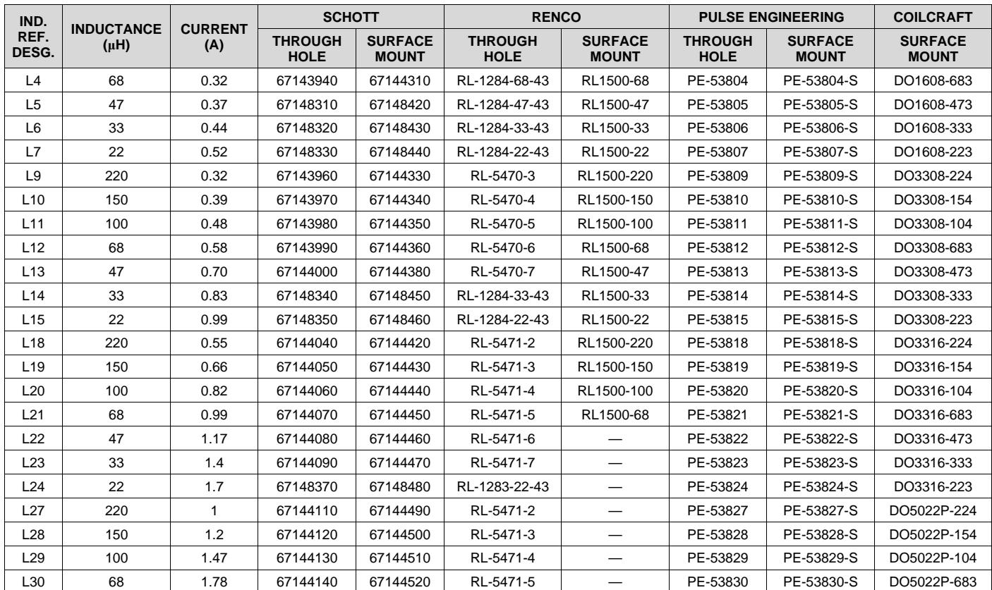
Select an appropriate inductor from the four manufacturer's part numbers listed in Table 2. Each manufacturer makes a different style of inductor to allow flexibility in meeting various design requirements. The inductance value required is 33 μH. From Table 2, go to the L23 line and choose an inductor part number from any of the four manufacturers shown. In most instances, both through hole and surface mount inductors are available.
Table 2. Inductor Manufacturers' Part Numbers
| IND. REF. DESG. | INDUCTANCE (μH) | CURRENT (A) | SCHOTT | RENCO | PULSE ENGINEERING | COILCRAFT | |||
| THROUGH HOLE | SURFACE MOUNT | THROUGH HOLE | SURFACE MOUNT | THROUGH HOLE | SURFACE MOUNT | SURFACE MOUNT | |||
| L4 | 68 | 0.32 | 67143940 | 67144310 | RL-1284-68-43 | RL1500-68 | PE-53804 | PE-53804-S | DO1608-683 |
| L5 | 47 | 0.37 | 67148310 | 67148420 | RL-1284-47-43 | RL1500-47 | PE-53805 | PE-53805-S | DO1608-473 |
| L6 | 33 | 0.44 | 67148320 | 67148430 | RL-1284-33-43 | RL1500-33 | PE-53806 | PE-53806-S | DO1608-333 |
| L7 | 22 | 0.52 | 67148330 | 67148440 | RL-1284-22-43 | RL1500-22 | PE-53807 | PE-53807-S | DO1608-223 |
| L9 | 220 | 0.32 | 67143960 | 67144330 | RL-5470-3 | RL1500-220 | PE-53809 | PE-53809-S | DO3308-224 |
| L10 | 150 | 0.39 | 67143970 | 67144340 | RL-5470-4 | RL1500-150 | PE-53810 | PE-53810-S | DO3308-154 |
| L11 | 100 | 0.48 | 67143980 | 67144350 | RL-5470-5 | RL1500-100 | PE-53811 | PE-53811-S | DO3308-104 |
| L12 | 68 | 0.58 | 67143990 | 67144360 | RL-5470-6 | RL1500-68 | PE-53812 | PE-53812-S | DO3308-683 |
| L13 | 47 | 0.70 | 67144000 | 67144380 | RL-5470-7 | RL1500-47 | PE-53813 | PE-53813-S | DO3308-473 |
| L14 | 33 | 0.83 | 67148340 | 67148450 | RL-1284-33-43 | RL1500-33 | PE-53814 | PE-53814-S | DO3308-333 |
| L15 | 22 | 0.99 | 67148350 | 67148460 | RL-1284-22-43 | RL1500-22 | PE-53815 | PE-53815-S | DO3308-223 |
| L18 | 220 | 0.55 | 67144040 | 67144420 | RL-5471-2 | RL1500-220 | PE-53818 | PE-53818-S | DO3316-224 |
| L19 | 150 | 0.66 | 67144050 | 67144430 | RL-5471-3 | RL1500-150 | PE-53819 | PE-53819-S | DO3316-154 |
| L20 | 100 | 0.82 | 67144060 | 67144440 | RL-5471-4 | RL1500-100 | PE-53820 | PE-53820-S | DO3316-104 |
| L21 | 68 | 0.99 | 67144070 | 67144450 | RL-5471-5 | RL1500-68 | PE-53821 | PE-53821-S | DO3316-683 |
| L22 | 47 | 1.17 | 67144080 | 67144460 | RL-5471-6 | — | PE-53822 | PE-53822-S | DO3316-473 |
| L23 | 33 | 1.4 | 67144090 | 67144470 | RL-5471-7 | — | PE-53823 | PE-53823-S | DO3316-333 |
| L24 | 22 | 1.7 | 67148370 | 67148480 | RL-1283-22-43 | — | PE-53824 | PE-53824-S | DO3316-223 |
| L27 | 220 | 1 | 67144110 | 67144490 | RL-5471-2 | — | PE-53827 | PE-53827-S | DO5022P-224 |
| L28 | 150 | 1.2 | 67144120 | 67144500 | RL-5471-3 | — | PE-53828 | PE-53828-S | DO5022P-154 |
| L29 | 100 | 1.47 | 67144130 | 67144510 | RL-5471-4 | — | PE-53829 | PE-53829-S | DO5022P-104 |
| L30 | 68 | 1.78 | 67144140 | 67144520 | RL-5471-5 | — | PE-53830 | PE-53830-S | DO5022P-683 |
10.2.1.2.2 Output Capacitor Selection (C )
Select an output capacitor from the output capacitor table in Table 3. Using the output voltage and the inductance value found in the inductor selection guide, step 1, locate the appropriate capacitor value and voltage rating. Use the 5-V section in Table 3. Choose a capacitor value and voltage rating from the line that contains the inductance value of 33 μH. The capacitance and voltage rating values corresponding to the 33 μH.
The capacitor list contains through-hole electrolytic capacitors from four different capacitor manufacturers and surface mount tantalum capacitors from two different capacitor manufacturers.
Surface mount:
• 68-μF, 10-V Sprague 594D series
• 100-μF, 10-V AVX TPS series
Through hole:
• 68-μF, 10-V Sanyo OS-CON SA series
• 220-μF, 35-V Sanyo MV-GX series
• 220-μF, 35-V Nichicon PL series
• 220-μF, 35-V Panasonic HFQ series
Table 3. Output Capacitor Table
| OUTPUT VOLTAGE (V) | INDUCTANCE (μH) | OUTPUT CAPACITOR | |||||
| SURFACE MOUNT | THROUGH HOLE | ||||||
| SPRAGUE 594D SERIES (μF/V) | AVX TPS SERIES (μF/V) | SANYO OS-CON SA SERIES (μF/V) | SANYO MV-GX SERIES (μF/V) | NICHICON PL SERIES (μF/V) | PANASONIC HFQ SERIES (μF/V) | ||
| 3.3 | 22 | 120/6.3 | 100/10 | 100/10 | 330/35 | 330/35 | 330/35 |
| 33 | 120/6.3 | 100/10 | 68/10 | 220/35 | 220/35 | 220/35 | |
| 47 | 68/10 | 100/10 | 68/10 | 150/35 | 150/35 | 150/35 | |
| 68 | 120/6.3 | 100/10 | 100/10 | 120/35 | 120/35 | 120/35 | |
| 100 | 120/6.3 | 100/10 | 100/10 | 120/35 | 120/35 | 120/35 | |
| 150 | 120/6.3 | 100/10 | 100/10 | 120/35 | 120/35 | 120/35 | |
| 5 | 22 | 100/16 | 100/10 | 100/10 | 330/35 | 330/35 | 330/35 |
| 33 | 68/10 | 100/10 | 68/10 | 220/35 | 220/35 | 220/35 | |
| 47 | 68/10 | 100/10 | 68/10 | 150/35 | 150/35 | 150/35 | |
| 68 | 100/16 | 100/10 | 100/10 | 120/35 | 120/35 | 120/35 | |
| 100 | 100/16 | 100/10 | 100/10 | 120/35 | 120/35 | 120/35 | |
| 150 | 100/16 | 100/10 | 100/10 | 120/35 | 120/35 | 120/35 | |
| 12 | 22 | 120/20 | (2×) 68/20 | 68/20 | 330/35 | 330/35 | 330/35 |
| 33 | 68/25 | 68/20 | 68/20 | 220/35 | 220/35 | 220/35 | |
| 47 | 47/20 | 68/20 | 47/20 | 150/35 | 150/35 | 150/35 | |
| 68 | 47/20 | 68/20 | 47/20 | 120/35 | 120/35 | 120/35 | |
| 100 | 47/20 | 68/20 | 47/20 | 120/35 | 120/35 | 120/35 | |
| 150 | 47/20 | 68/20 | 47/20 | 120/35 | 120/35 | 120/35 | |
| 220 | 47/20 | 68/20 | 47/20 | 120/35 | 120/35 | 120/35 | |
10.2.1.2.3 Catch Diode Selection (D1)
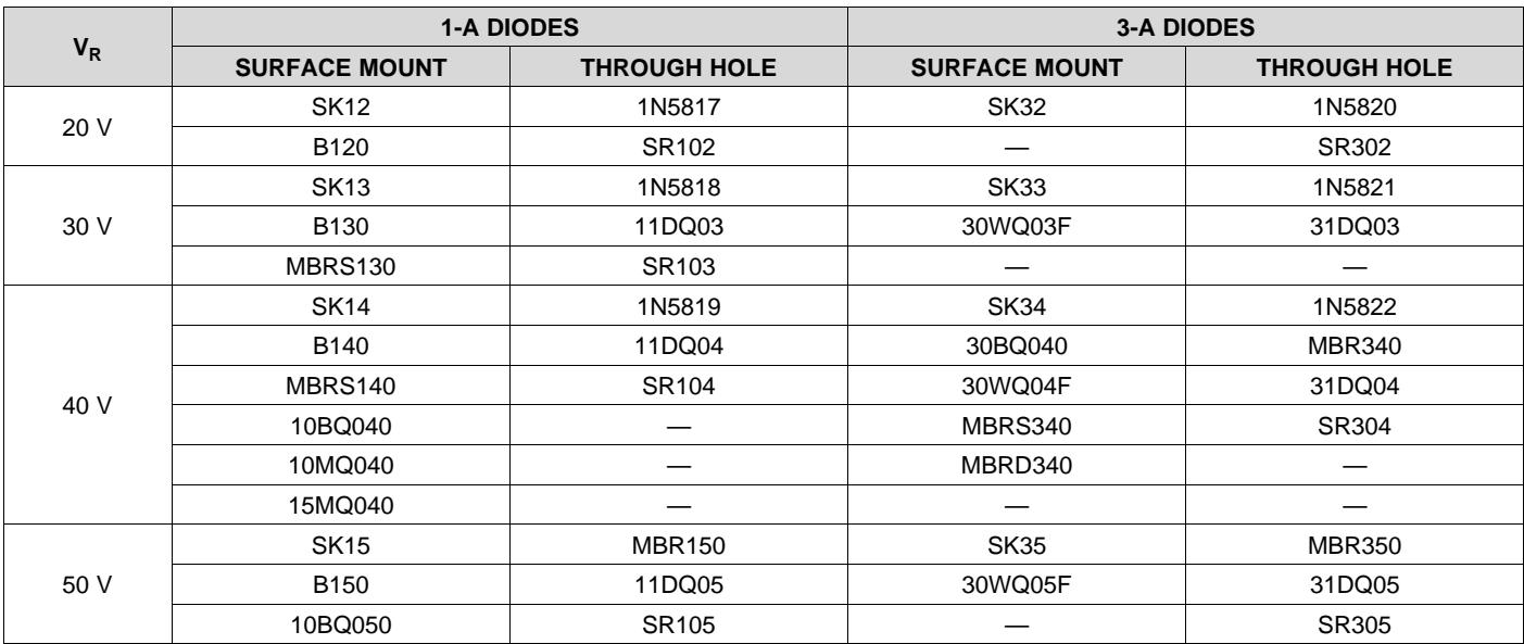
In normal operation, the average current of the catch diode is the load current times the catch diode duty cycle, 1-D (D is the switch duty cycle, which is approximately the output voltage divided by the input voltage). The largest value of the catch diode average current occurs at the maximum load current and maximum input voltage (minimum D). For normal operation, the catch diode current rating must be at least 1.3 times greater than its maximum average current. However, if the power supply design must withstand a continuous output short, the diode must have a current rating equal to the maximum current limit of the LM2672. The most stressful condition for this diode is a shorted output condition. Refer to the table shown in Table 4. In this example, a 1-A, 20-V Schottky diode provides the best performance. If the circuit must withstand a continuous shorted output, a higher current Schottky diode is recommended.
The reverse voltage rating of the diode must be at least 1.25 times the maximum input voltage. Because of their fast switching speed and low forward voltage drop, Schottky diodes provide the best performance and efficiency. This Schottky diode must be placed close to the LM2672 using short leads and short printed circuit traces.
Table 4. Schottky Diode Selection Table
| $V_R$ | 1-A DIODES | 3-A DIODES | ||
| SURFACE MOUNT | THROUGH HOLE | SURFACE MOUNT | THROUGH HOLE | |
| 20 V | SK12 | 1N5817 | SK32 | 1N5820 |
| B120 | SR102 | — | SR302 | |
| 30 V | SK13 | 1N5818 | SK33 | 1N5821 |
| B130 | 11DQ03 | 30WQ03F | 31DQ03 | |
| MBRS130 | SR103 | — | — | |
| 40 V | SK14 | 1N5819 | SK34 | 1N5822 |
| B140 | 11DQ04 | 30BQ040 | MBR340 | |
| MBRS140 | SR104 | 30WQ04F | 31DQ04 | |
| 10BQ040 | — | MBRS340 | SR304 | |
| 10MQ040 | — | MBRD340 | — | |
| 15MQ040 | — | — | — | |
| 50 V | SK15 | MBR150 | SK35 | MBR350 |
| B150 | 11DQ05 | 30WQ05F | 31DQ05 | |
| 10BQ050 | SR105 | — | SR305 | |
10.2.1.2.4 Input Capacitor $( \mathsf { C } _ { \mathsf { I N } } )$
A low ESR aluminum or tantalum bypass capacitor is required between the input pin and ground to prevent large voltage transients from appearing at the input. This capacitor must be placed close to the IC using short leads. In addition, the RMS current rating of the input capacitor must be selected to be at least ½ the DC load current. The capacitor manufacturer data sheet must be checked to assure that this current rating is not exceeded. Figure 21 shows typical RMS current ratings for several different aluminum electrolytic capacitor values. A paralle connection of two or more capacitors may be required to increase the total minimum RMS current rating to suit the application requirements.
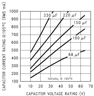
Figure 21. RMS Current Ratings for Low ESR Electrolytic Capacitors (Typical)
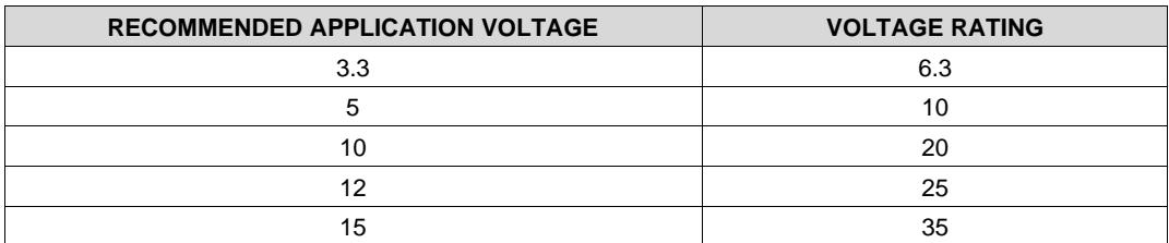
For an aluminum electrolytic capacitor, the voltage rating must be at least 1.25 times the maximum input voltage. Caution must be exercised if solid tantalum capacitors are used. The tantalum capacitor voltage rating must be twice the maximum input voltage. The tables in Table 5 show the recommended application voltage for AVX TPS and Sprague 594D tantalum capacitors. It is also recommended that they be surge current tested by the manufacturer. The TPS series available from AVX, and the 593D and 594D series from Sprague are all surge current tested. Another approach to minimize the surge current stresses on the input capacitor is to add a small inductor in series with the input supply line.
Table 5. Recommended Application Voltage for AVX TPS and Sprague 594D Tantalum Chip Capacitors Derated for $\mathtt { \pmb { 8 5 } ^ { \circ } C }$
| RECOMMENDED APPLICATION VOLTAGE | VOLTAGE RATING |
| 3.3 | 6.3 |
| 5 | 10 |
| 10 | 20 |
| 12 | 25 |
| 15 | 35 |
Use caution when using ceramic capacitors for input bypassing, because it may cause severe ringing at the $V _ { \sf I N }$ pin.
The important parameters for the input capacitor are the input voltage rating and the RMS current rating. With a maximum input voltage of 12 V, an aluminum electrolytic capacitor with a voltage rating greater than 15 V (1.25 × $\mathsf { V } _ { \mathsf { I N } } )$ is required. The next higher capacitor voltage rating is 16 V.
The RMS current rating requirement for the input capacitor in a buck regulator is approximately ½ the DC load current. In this example, with a 1-A load, a capacitor with a RMS current rating of at least 500 mA is required. The curves shown in Figure 21 can be used to select an appropriate input capacitor. From the curves, locate the 16-V line and note which capacitor values have RMS current ratings greater than 500 mA.
For a through hole design, a 330-μF, 16-V electrolytic capacitor (Panasonic HFQ series, Nichicon PL, Sanyo MV-GX series or equivalent) would be adequate. Other types or other manufacturers' capacitors can be used provided the RMS ripple current ratings are adequate. Additionally, for a complete surface mount design, electrolytic capacitors such as the Sanyo CV-C or CV-BS and the Nichicon WF or UR and the NIC Components NACZ series could be considered.
For surface mount designs, solid tantalum capacitors can be used, but caution must be exercised with regard to the capacitor surge current rating and voltage rating. In this example, checking Table 5, and the Sprague 594D series data sheet, a Sprague 594D 15-μF, 25-V capacitor is adequate.
10.2.1.2.5 Boost Capacitor $( C _ { \mathsf { B } } )$
This capacitor develops the necessary voltage to turn the switch gate on fully. All applications must use a 0.01- μF, 50-V ceramic capacitor.
10.2.1.2.6 Soft-Start Capacitor $( \cos ,$ , Optional)
This capacitor controls the rate at which the device starts up. The formula for the soft-start capacitor $\mathtt { C } _ { \mathtt { S S } }$ is calculated with Equation 1.
$$
C _ {S S} \approx \left(I _ {S S} \cdot t _ {S S}\right) / \left[ V _ {S S T H} + 2. 6 V \cdot \left(\frac {V _ {O U T} + V _ {S C H O T T K Y}}{V _ {I N}}\right) \right]
$$
where
• ISS = Soft-start current (4.5 µA, typical)
$\mathfrak { t } _ { \mathbb { S } \mathbb { S } } =$ Soft-start time (selected)
$\mathsf { V } _ { \mathsf { S S T H } }$ = Soft-start threshold voltage (0.63 V, typical)
$\mathsf { V } _ { \mathsf { O U T } } = ($ Output voltage (selected)
$\mathsf { V } _ { \mathsf { S C H O T T K Y } } = \mathsf { S c h o t t k y }$ diode voltage drop (0.4 V, typical)
• VIN = Input voltage (selected)
(1)
If this feature is not desired, leave this pin open. With certain soft-start capacitor values and operating conditions, the LM2672 can exhibit an overshoot on the output voltage during turn on. Especially when starting up into no load or low load, the soft-start function may not be effective in preventing a larger voltage overshoot on the output. With larger loads or lower input voltages during startup this effect is minimized. In particular, avoid using soft-start capacitors between 0.033 $\mathsf { \Pi } \dot { \mu } \mathsf { F }$ and 1 µF.
For this application, selecting a start-up time of 10 ms and using the formula for $\mathtt { C } _ { \mathtt { S S } }$ results in a value of Equation 2.
$$
\begin{array}{r l} C _ {S S} \approx (4. 5 \mu A \cdot 1 0 m s) / [ 0. 6 3 V + 2. 6 V \cdot (\frac {5 V + 0 . 4 V}{1 2 V}) ] \ = 2 5 n F \approx 0. 0 2 2 \mu F. \end{array}\tag{2}
$$
10.2.1.2.7 Frequency Synchronization (Optional)
The LM2672 (oscillator) can be synchronized to run with an external oscillator, using the sync pin (pin 3). By doing so, the LM2672 can be operated at higher frequencies than the standard frequency of 260 kHz. This allows for a reduction in the size of the inductor and output capacitor.
As shown in Figure 22, a signal applied to a RC filter at the sync pin causes the device to synchronize to the frequency of that signal. For a signal with a peak-to-peak amplitude of 3 V or greater, a 1-kΩ resistor and a 100- pF capacitor are suitable values. For all applications, use a 1-kΩ resistor and a 100-pF capacitor for the RC filter.
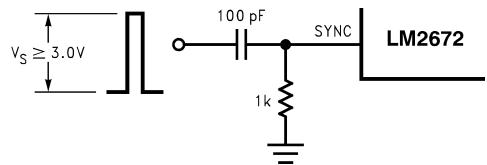
Figure 22. Synchronization on LM2672
10.2.1.3 Application Curves
Figure 23. LM2672, 3.3-V Output
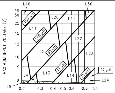
MAXIMUM LOAD CURRENT (A) Figure 24. LM2672, 5-V Output
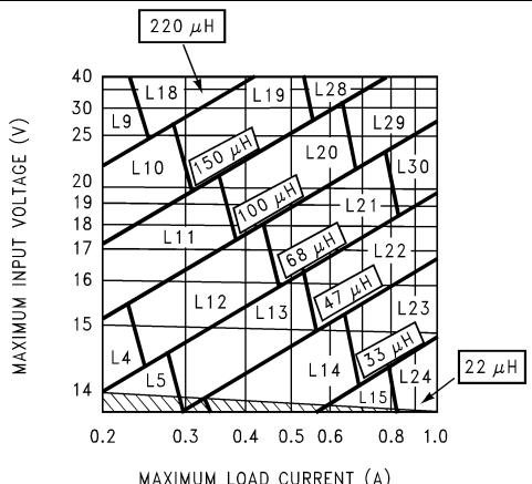
Figure 25. LM2672, 12-V Output
10.2.2 Typical Application for Adjustable Output Voltage Versions
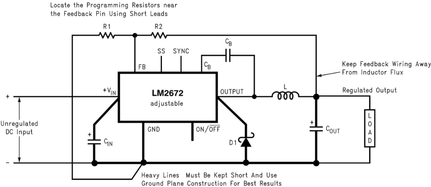
Copyright © 2016, Texas Instruments Incorporated
CIN = 22-μF, 50-V Tantalum, Sprague 199D Series
D1 = 3.3-A, 50-V Schottky Rectifier, IR 30WQ05F
R1 = 1.5-kΩ , 1%
$\mathsf { C } _ { \mathsf { B } } = 0 . 0 1 \mathsf { - } \mu \mathsf { F }$ , 50-V Ceramic
Figure 26. Adjustable Output Voltage Typical Application
10.2.2.1 Design Requirements
Table 6 lists the design requirements for the adjustable output voltage application.
Table 6. Adjustable Output Voltage Application Parameters
| PARAMETERS | VALUE |
| Regulated output voltage, $V_{OUT}$ | 20 V |
| Maximum input voltage, $V_{IN(max)}$ | 28 V |
| Maximum load current, $I_{LOAD(max)}$ | 1 A |
| Switching frequency, F | Fixed at a nominal 260 kHz |
10.2.2.2 Detailed Design Procedure
10.2.2.2.1 Programming Output Voltage
For this application, TI recommends selecting $\mathsf { R } _ { 1 }$ and $\mathsf { R } _ { 2 } ,$ as shown in Parameter Measurement Information. Use Equation 3 to select the appropriate resistor values.
$$
V _ {O U T} = V _ {R E F} \left(1 + \frac {R _ {2}}{R _ {1}}\right)
$$
$$
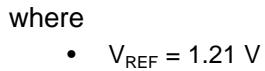
\begin{array}{l} \text {where} \ \bullet \quad V _ {\text {REF}} = 1. 2 1 \mathrm{V} \end{array}\tag{3}
$$
Select a value for $\mathsf { R } _ { 1 }$ between 240 Ω and 1.5 kΩ. The lower resistor values minimize noise pickup in the sensitive feedback pin. For the lowest temperature coefficient and the best stability with time, use 1% metal film resistors as in Equation 4.
$$
R _ {2} = R _ {1} \left(\frac {V _ {\mathrm{OUT}}}{V _ {\mathrm{REF}}} - 1\right)\tag{4}
$$
For this application example, select ${ \mathsf { R } } _ { 1 }$ to be 1 kΩ, 1%. Solve for ${ \sf R } _ { 2 }$ with Equation 5.
$$
R _ {2} = R _ {1} \left(\frac {V _ {\mathrm{OUT}}}{V _ {\mathrm{REF}}} - 1\right) = 1 \mathrm{k} \Omega \left(\frac {2 0 \mathrm{V}}{1 . 2 3 \mathrm{V}} - 1\right)\tag{5}
$$
R = 1 kΩ (16.53 − 1) = 15.53 kΩ, closest 1% value is 15.4 kΩ.
$$
\mathsf {R} _ {2} = 1 5. 4 \mathrm{k} \Omega .
$$
10.2.2.2.2 Inductor Selection (L1)
Calculate the inductor Volt × microsecond constant E × T $( \mathsf { V } \times \mathsf { \mu } \mathsf { s } )$ with Equation 6.
$$
E \cdot T = \left(V _ {I N (M A X)} - V _ {O U T} - V _ {S A T}\right) \cdot \frac {V _ {O U T} + V _ {D}}{V _ {I N (M A X)} - V _ {S A T} + V _ {D}} \cdot \frac {1 0 0 0}{2 6 0} (V \cdot \mu s)
$$
where
• VSAT = internal switch saturation voltage = 0.25 V
• V = diode forward voltage drop = 0.5 V
(6)
For this application example, calculate the inductor Volt × microsecond constant (E × T) with Equation 7.
$$
\begin{array}{l} \mathrm{E} \cdot \mathrm{T} = (2 8 - 2 0 - 0. 2 5) \cdot \frac {2 0 + 0 . 5}{2 8 - 0 . 2 5 + 0 . 5} \cdot \frac {1 0 0 0}{2 6 0} (\mathrm{V} \cdot \mu \mathrm{s}) \ \mathrm{E} \cdot \mathrm{T} = (7. 7 5) \cdot \frac {2 0 . 5}{2 8 . 2 5} \cdot 3. 8 5 (\mathrm{V} \cdot \mu \mathrm{s}) = 2 1. 6 (\mathrm{V} \cdot \mu \mathrm{s}) \end{array}\tag{7}
$$
Use the E × T value from the previous formula and match it with the E × T number on the vertical axis of the inductor value selection guide in Figure 27. E × T = 21.6 (V × μs).
On the horizontal axis, select the maximum load current $( \mathsf { I } _ { \mathsf { L O A D } } ( \mathsf { m a x } ) = 1 \ \mathsf { A } )$
Identify the inductance region intersected by the E × T value and the maximum load current value. Each region is identified by an inductance value and an inductor code (LXX). From the inductor value selection guide shown in Figure 27, the inductance region intersected by the 21.6 (V × μs) horizontal line and the 1-A vertical line is 68 μH, and the inductor code is L30.
Select an appropriate inductor from the four manufacturer's part numbers listed in Table 2. For information on the different types of inductors, see the inductor selection in the fixed output voltage design procedure. From the table in Table 2, locate line L30, and select an inductor part number from the list of manufacturers' part numbers.
10.2.2.2.3 Output Capacitor SeIection (C )
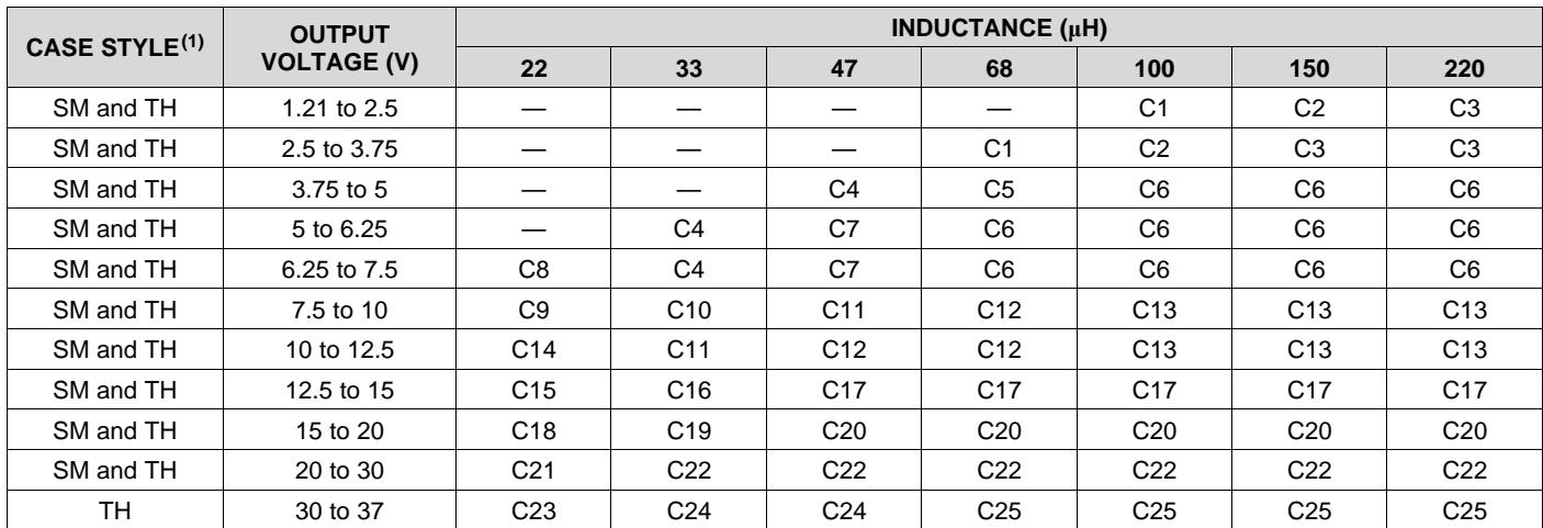
Select an output capacitor from the capacitor code selection guide in Table 7. Using the inductance value found in the inductor selection guide, step 1, locate the appropriate capacitor code corresponding to the desired outpu voltage. Use the appropriate row of the capacitor code selection guide, in Table 7. For this example, use the 15 to 20 V row. The capacitor code corresponding to an inductance of 68 μH is C20.
Table 7. Capacitor Code Selection Guide
| CASE STYLE(1) | OUTPUT VOLTAGE (V) | INDUCTANCE (μH) | ||||||
| 22 | 33 | 47 | 68 | 100 | 150 | 220 | ||
| SM and TH | 1.21 to 2.5 | — | — | — | — | C1 | C2 | C3 |
| SM and TH | 2.5 to 3.75 | — | — | — | C1 | C2 | C3 | C3 |
| SM and TH | 3.75 to 5 | — | — | C4 | C5 | C6 | C6 | C6 |
| SM and TH | 5 to 6.25 | — | C4 | C7 | C6 | C6 | C6 | C6 |
| SM and TH | 6.25 to 7.5 | C8 | C4 | C7 | C6 | C6 | C6 | C6 |
| SM and TH | 7.5 to 10 | C9 | C10 | C11 | C12 | C13 | C13 | C13 |
| SM and TH | 10 to 12.5 | C14 | C11 | C12 | C12 | C13 | C13 | C13 |
| SM and TH | 12.5 to 15 | C15 | C16 | C17 | C17 | C17 | C17 | C17 |
| SM and TH | 15 to 20 | C18 | C19 | C20 | C20 | C20 | C20 | C20 |
| SM and TH | 20 to 30 | C21 | C22 | C22 | C22 | C22 | C22 | C22 |
| TH | 30 to 37 | C23 | C24 | C24 | C25 | C25 | C25 | C25 |
(1) SM = surface mount, TH = through hole
Select an appropriate capacitor value and voltage rating, using the capacitor code, from the output capacitor selection table in Table 8. There are two solid tantalum (surface mount) capacitor manufacturers and four electrolytic (through hole) capacitor manufacturers to choose from. TI recommends that both the manufacturers and the manufacturer's series that are listed in the table be used. From the output capacitor selection table in Table 8, choose a capacitor value (and voltage rating) that intersects the capacitor code(s) selected in section A, C20 (Table 8).
The capacitance and voltage rating values corresponding to the capacitor code C20 are surface mount and through hole.
Surface mount:
• 33-μF, 25-V Sprague 594d series
• 33-μF, 25-V AVX TPS series
Through hole:
• 33-μF, 25-V Sanyo OS-CON SC series
• 120-μF, 35-V Sanyo MV-GX series
• 120-μF, 35-V Nichicon PL series
• 120-μF, 35-V Panasonic HFQ series
Other manufacturers or other types of capacitors may also be used, provided the capacitor specifications (especially the 100 kHz ESR) closely match the characteristics of the capacitors listed in the output capacitor table. Refer to the capacitor manufacturers' data sheet for this information.
Table 8. Output Capacitor Selection Table
| OUTPUT CAPACITOR | ||||||
| CAP. REF. DESG.# | SURFACE MOUNT | THROUGH HOLE | ||||
| SPRAGUE 594D SERIES (μF/V) | AVX TPSSERIES (μF/V) | SANYO OS-CON SA SERIES (μF/V) | SANYO MV-GX SERIES (μF/V) | NICHICON PL SERIES (μF/V) | PANASONIC HFQ SERIES (μF/V) | |
| C1 | 120/6.3 | 100/10 | 100/10 | 220/35 | 220/35 | 220/35 |
| C2 | 120/6.3 | 100/10 | 100/10 | 150/35 | 150/35 | 150/35 |
| C3 | 120/6.3 | 100/10 | 100/35 | 120/35 | 120/35 | 120/35 |
| C4 | 68/10 | 100/10 | 68/10 | 220/35 | 220/35 | 220/35 |
| C5 | 100/16 | 100/10 | 100/10 | 150/35 | 150/35 | 150/35 |
| C6 | 100/16 | 100/10 | 100/10 | 120/35 | 120/35 | 120/35 |
| C7 | 68/10 | 100/10 | 68/10 | 150/35 | 150/35 | 150/35 |
| C8 | 100/16 | 100/10 | 100/10 | 330/35 | 330/35 | 330/35 |
| C9 | 100/16 | 100/16 | 100/16 | 330/35 | 330/35 | 330/35 |
| C10 | 100/16 | 100/16 | 68/16 | 220/35 | 220/35 | 220/35 |
| C11 | 100/16 | 100/16 | 68/16 | 150/35 | 150/35 | 150/35 |
| C12 | 100/16 | 100/16 | 68/16 | 120/35 | 120/35 | 120/35 |
| C13 | 100/16 | 100/16 | 100/16 | 120/35 | 120/35 | 120/35 |
| C14 | 100/16 | 100/16 | 100/16 | 220/35 | 220/35 | 220/35 |
| C15 | 47/20 | 68/20 | 47/20 | 220/35 | 220/35 | 220/35 |
| C16 | 47/20 | 68/20 | 47/20 | 150/35 | 150/35 | 150/35 |
| C17 | 47/20 | 68/20 | 47/20 | 120/35 | 120/35 | 120/35 |
| C18 | 68/25 | (2x) 33/25 | $47/25^{(1)}$ | 220/35 | 220/35 | 220/35 |
| C19 | 33/25 | 33/25 | $33/25^{(1)}$ | 150/35 | 150/35 | 150/35 |
| C20 | 33/25 | 33/25 | $33/25^{(1)}$ | 120/35 | 120/35 | 120/35 |
| C21 | 33/35 | (2x) 22/25 | $See^{(2)}$ | 150/35 | 150/35 | 150/35 |
| C22 | 33/35 | 22/35 | $See^{(2)}$ | 120/35 | 120/35 | 120/35 |
| C23 | $See^{(2)}$ | $See^{(2)}$ | $See^{(2)}$ | 220/50 | 100/50 | 120/50 |
| C24 | $See^{(2)}$ | $See^{(2)}$ | $See^{(2)}$ | 150/50 | 100/50 | 120/50 |
| C25 | $See^{(2)}$ | $See^{(2)}$ | $See^{(2)}$ | 150/50 | 82/50 | 82/50 |
(1) The SC series of Os-Con capacitors (others are SA series)
(2) The voltage ratings of the surface mount tantalum chip and Os-Con capacitors are too low to work at these voltages.
10.2.2.2.4 Catch Diode Selection (D1)
In normal operation, the average current of the catch diode is the load current times the catch diode duty cycle, 1-D (D is the switch duty cycle, which is approximately $\mathsf { V _ { O U T } } / \mathsf { V _ { I N } } )$ . The largest value of the catch diode average current occurs at the maximum input voltage (minimum D). For normal operation, the catch diode current rating must be at least 1.3 times greater than its maximum average current. However, if the power supply design must withstand a continuous output short, the diode must have a current rating greater than the maximum current limit of the LM2672. The most stressful condition for this diode is a shorted output condition. Refer to the table shown in Table 4. Schottky diodes provide the best performance, and in this example a 1-A, 40-V Schottky diode would be a good choice. If the circuit must withstand a continuous shorted output, a higher current (at least 2.2-A) Schottky diode is recommended.
The reverse voltage rating of the diode must be at least 1.25 times the maximum input voltage. Because of their fast switching speed and low forward voltage drop, Schottky diodes provide the best performance and efficiency. The Schottky diode must be placed close to the LM2672 using short leads and short printed circuit traces.
10.2.2.2.5 Input Capacitor $( \mathsf { C } _ { \mathsf { I N } } )$
A low ESR aluminum or tantalum bypass capacitor is required between the input pin and ground to prevent large voltage transients from appearing at the input. This capacitor must be placed close to the IC using short leads. In addition, the RMS current rating of the input capacitor must be selected to be at least ½ the DC load current. The capacitor manufacturer data sheet must be checked to assure that this current rating is not exceeded. Figure 21 shows typical RMS current ratings for several different aluminum electrolytic capacitor values. A parallel connection of two or more capacitors may be required to increase the total minimum RMS current rating to suit the application requirements.
For an aluminum electrolytic capacitor, the voltage rating must be at least 1.25 times the maximum input voltage. Caution must be exercised if solid tantalum capacitors are used. The tantalum capacitor voltage rating must be twice the maximum input voltage. The tables in Table 5 show the recommended application voltage for AVX TPS and Sprague 594D tantalum capacitors. It is also recommended that they be surge current tested by the manufacturer. The TPS series available from AVX, and the 593D and 594D series from Sprague are all surge current tested. Another approach to minimize the surge current stresses on the input capacitor is to add a small inductor in series with the input supply line.
Use caution when using ceramic capacitors for input bypassing, because it may cause severe ringing at the $V _ { \sf I N }$ pin.
The important parameters for the input capacitor are the input voltage rating and the RMS current rating. With a maximum input voltage of 28 V, an aluminum electrolytic capacitor with a voltage rating of at least 35 V (1.25 × $\mathsf { V } _ { \mathsf { I N } } )$ is required.
The RMS current rating requirement for the input capacitor in a buck regulator is approximately ½ the DC load current. In this example, with a 1-A load, a capacitor with a RMS current rating of at least 500 mA is required. The curves shown in Figure 21 can be used to select an appropriate input capacitor. From the curves, locate the 35-V line and note which capacitor values have RMS current ratings greater than 500 mA.
For a through hole design, a 330-μF, 35-V electrolytic capacitor (Panasonic HFQ series, Nichicon PL, Sanyo MV-GX series or equivalent) would be adequate. Other types or other manufacturers' capacitors can be used provided the RMS ripple current ratings are adequate. Additionally, for a complete surface mount design, electrolytic capacitors such as the Sanyo CV-C or CV-BS and the Nichicon WF or UR and the NIC Components NACZ series could be considered.
For surface mount designs, solid tantalum capacitors can be used, but caution must be exercised with regard to the capacitor surge current rating and voltage rating. In this example, checking Table 5, and the Sprague 594D series datasheet, a Sprague 594D 15-μF, 50-V capacitor is adequate.
10.2.2.2.6 Boost Capacitor (C )
This capacitor develops the necessary voltage to turn the switch gate on fully. All applications must use a 0.01-μF, 50-V ceramic capacitor. If the soft-start and frequency synchronization features are desired, see steps 6 and 7 in the fixed output design procedure.
10.2.2.3 Application Curve

Figure 27. LM2672, Adjustable Output
11 Power Supply Recommendations
The input voltage for the power supply is connected to the $V _ { \sf I N }$ pin. In addition to providing energy to the load the input voltage also provides bias for the internal circuitry of the LM2672. For ensured performance, the input voltage must be in the range of 6.5 V to 40 V. For best performance of the power supply, the $V _ { \sf I N }$ pin must always be bypassed with an input capacitor placed close to this pin and GND.
12 Layout
12.1 Layout Guidelines
Layout is very important in switching regulator designs. Rapidly switching currents associated with wiring inductance can generate voltage transients which can cause problems. For minimal inductance and ground loops, the wires indicated by heavy lines (in Figure 19) must be wide printed circuit traces and must be kept as short as possible. For best results, external components must be placed as close to the switcher IC as possible using ground plane construction or single point grounding.
This is the ground reference connection for all components in the power supply. In fast-switching, high-current applications such as those implemented with the LM2672, TI recommends that a broad ground plane be used to minimize signal coupling throughout the circuit.
If open-core inductors are used, take special care as to the location and positioning of this type of inductor. Allowing the inductor flux to intersect sensitive feedback, IC ground path, and ${ \mathsf { C } } _ { \mathsf { O U T } }$ wiring can cause problems.
When using the adjustable version, take special care as to the location of the feedback resistors and the associated wiring. Physically place both resistors near the IC, and route the wiring away from the inductor, especially an open core type of inductor.
12.1.1 WSON Package Devices
The LM2672 is offered in the 16-pin WSON surface mount package to allow for increased power dissipation compared to the 8-pin SOIC and PDIP.
The Die Attach Pad (DAP) can and must be connected to PCB Ground plane/island. For CAD and assembly guidelines, refer to AN-1187 Leadless Leadframe Package (LLP).
12.2 Layout Examples


$\mathsf { C } _ { \mathsf { I N } } = 1 5 \mathsf { - } \mathsf { \mu F } , 5 0 \mathsf { - } \mathsf { V } ,$ solid tantalum Sprague 594D series
COUT = 68-μF, 16-V, solid tantalum Sprague 594D series
D1 = 1-A, 40-V Schottky rectifier, surface mount
L1 = 33-μH, L23, coilcraft DO3316
$\mathsf { C } _ { \mathsf { B } } = 0 . 0 1 \mathsf { - \mu F }$ , 50-V ceramic
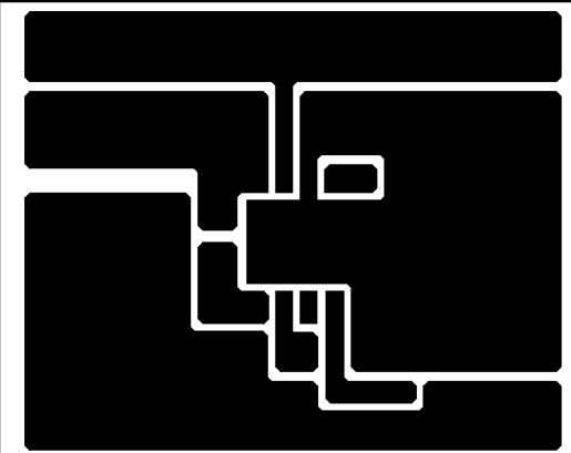
Figure 28. Typical Surface Mount PC Board Layout, Fixed Output
Layout Examples (continued)
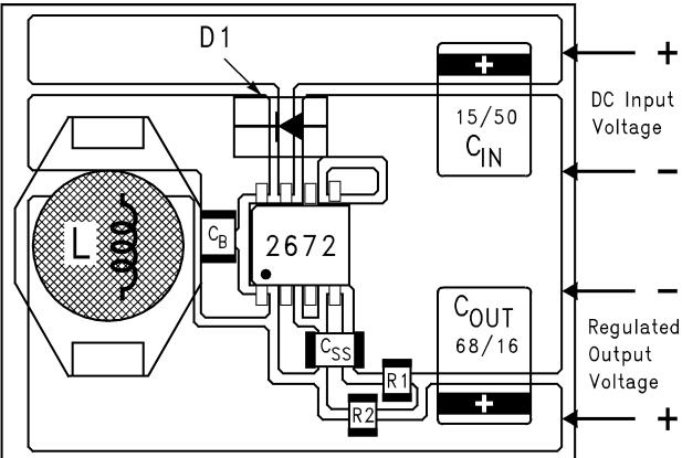
C = 15-μF, 50-V, solid tantalum Sprague 594D series
C = 33-μF, 25-V, solid tantalum Sprague 594D series
D1 = 1-A, 40-V Schottky rectifier, surface mount
L1 = 68-μH, L30, coilcraft DO3316
$\mathsf { C } _ { \mathsf { B } } = 0 . 0 1 \mathsf { - } \mu \mathsf { F } ,$ , 50-V ceramic
R1 = 1k, 1%, R2: use formula in Detailed Design Procedure
Figure 29. Typical Surface Mount PC Board Layout, Adjustable Output
13 Device and Documentation Support
13.1 Documentation Support
13.1.1 Related Documentation
For related documentation see the following:
LM2670 SIMPLE SWITCHER® High Efficiency 3A Step-Down Voltage Regulator with Sync (SNVS036)
• AN-1187 Leadless Leadframe Package (LLP) (SNOA401)
13.2 Receiving Notification of Documentation Updates
To receive notification of documentation updates, navigate to the device product folder on ti.com. In the upper right corner, click on Alert me to register and receive a weekly digest of any product information that has changed. For change details, review the revision history included in any revised document.
13.3 Community Resources
The following links connect to TI community resources. Linked contents are provided "AS IS" by the respective contributors. They do not constitute TI specifications and do not necessarily reflect TI's views; see TI's Terms of Use.
TI E2E™ Online Community TI's Engineer-to-Engineer (E2E) Community. Created to foster collaboration among engineers. At e2e.ti.com, you can ask questions, share knowledge, explore ideas and help solve problems with fellow engineers.
Design Support TI's Design Support Quickly find helpful E2E forums along with design support tools and contact information for technical support.
13.4 Trademarks
E2E is a trademark of Texas Instruments.
SIMPLE SWITCHER, WEBENCH are registered trademarks of Texas Instruments.
All other trademarks are the property of their respective owners.
13.5 Electrostatic Discharge Caution

These devices have limited built-in ESD protection. The leads should be shorted together or the device placed in conductive foam during storage or handling to prevent electrostatic damage to the MOS gates.
13.6 Glossary
SLYZ022 — TI Glossary.
This glossary lists and explains terms, acronyms, and definitions.
14 Mechanical, Packaging, and Orderable Information
The following pages include mechanical, packaging, and orderable information. This information is the most current data available for the designated devices. This data is subject to change without notice and revision of this document. For browser-based versions of this data sheet, refer to the left-hand navigation.
14.1 DAP (WSON Package)
The die attach pad (DAP) must be connected to the PCB ground plane. For CAD and assembly guidelines, refer to AN-1187 Leadless Leadframe Package (LLP).
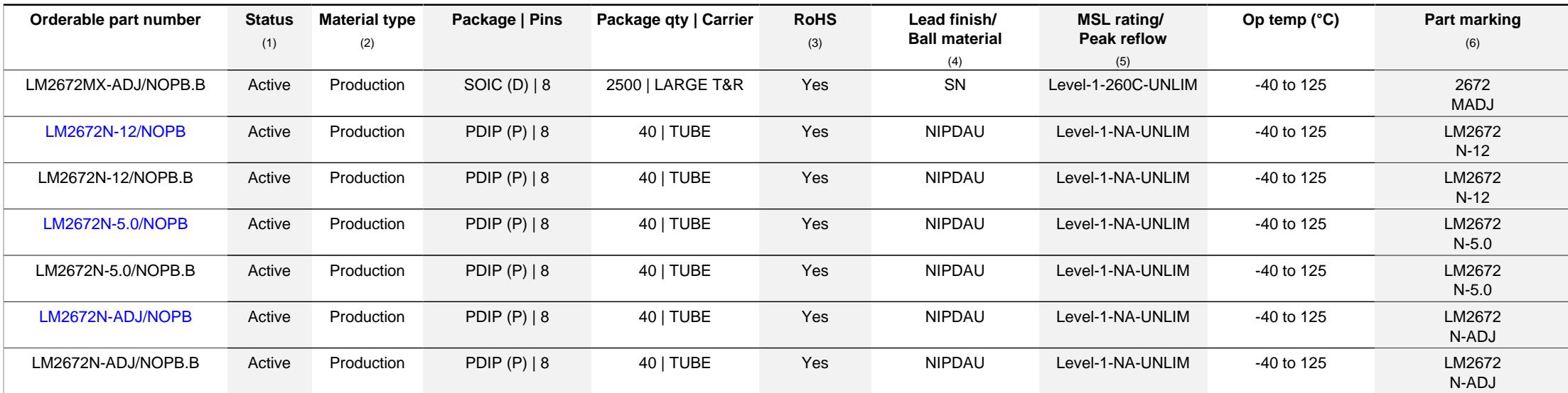
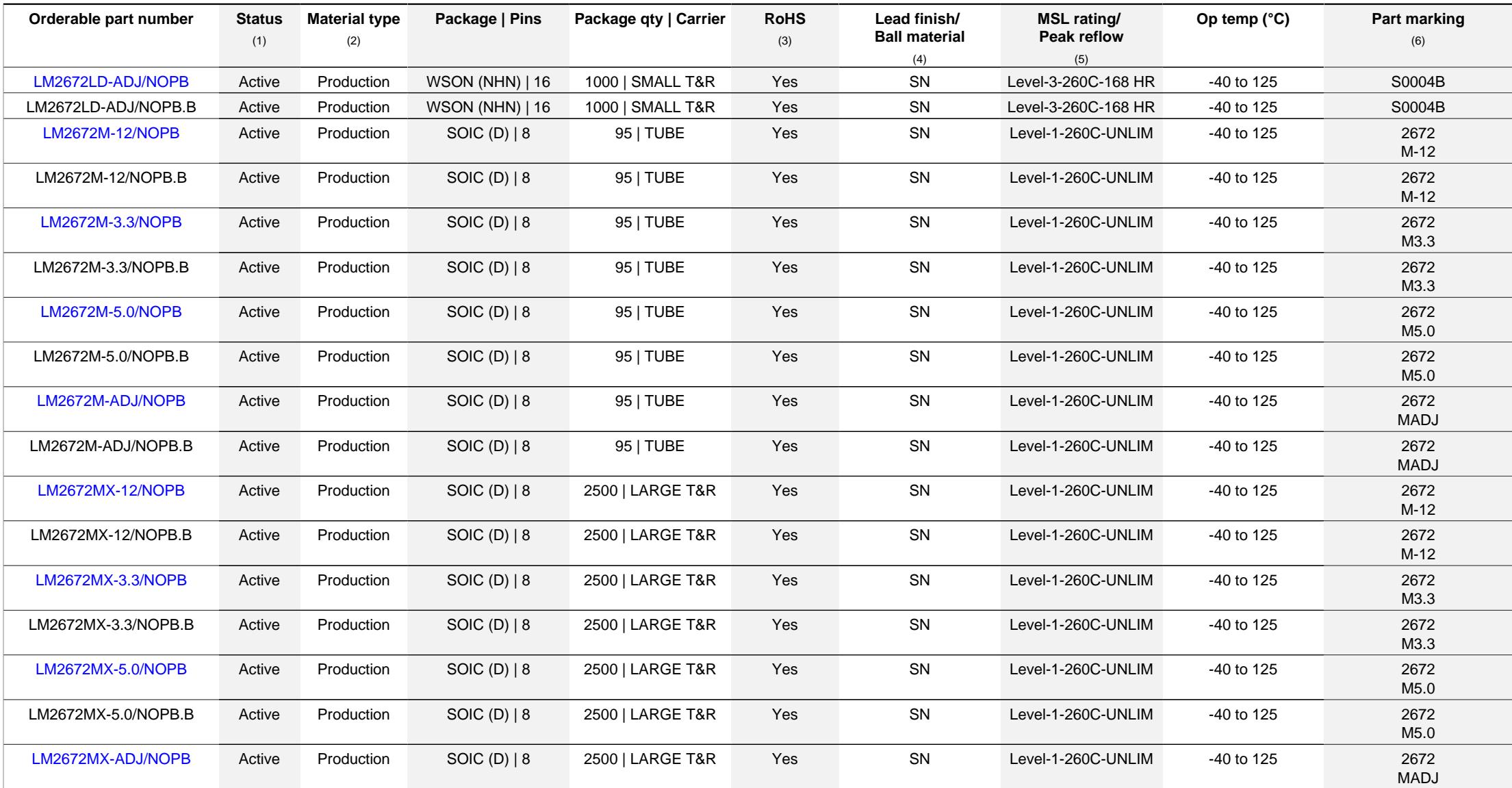
PACKAGING INFORMATION
| Orderable part number | Status(1) | Material type(2) | Package | Pins | Package qty | Carrier | RoHS(3) | Lead finish/ Ball material(4) | MSL rating/ Peak reflow(5) | Op temp (°C) | Part marking(6) |
| LM2672LD-ADJ/NOPB | Active | Production | WSON (NHN) | 16 | 1000 | SMALL T&R | Yes | SN | Level-3-260C-168 HR | -40 to 125 | S0004B |
| LM2672LD-ADJ/NOPB.B | Active | Production | WSON (NHN) | 16 | 1000 | SMALL T&R | Yes | SN | Level-3-260C-168 HR | -40 to 125 | S0004B |
| LM2672M-12/NOPB | Active | Production | SOIC (D) | 8 | 95 | TUBE | Yes | SN | Level-1-260C-UNLIM | -40 to 125 | 2672M-12 |
| LM2672M-12/NOPB.B | Active | Production | SOIC (D) | 8 | 95 | TUBE | Yes | SN | Level-1-260C-UNLIM | -40 to 125 | 2672M-12 |
| LM2672M-3.3/NOPB | Active | Production | SOIC (D) | 8 | 95 | TUBE | Yes | SN | Level-1-260C-UNLIM | -40 to 125 | 2672M3.3 |
| LM2672M-3.3/NOPB.B | Active | Production | SOIC (D) | 8 | 95 | TUBE | Yes | SN | Level-1-260C-UNLIM | -40 to 125 | 2672M3.3 |
| LM2672M-5.0/NOPB | Active | Production | SOIC (D) | 8 | 95 | TUBE | Yes | SN | Level-1-260C-UNLIM | -40 to 125 | 2672M5.0 |
| LM2672M-5.0/NOPB.B | Active | Production | SOIC (D) | 8 | 95 | TUBE | Yes | SN | Level-1-260C-UNLIM | -40 to 125 | 2672M5.0 |
| LM2672M-ADJ/NOPB | Active | Production | SOIC (D) | 8 | 95 | TUBE | Yes | SN | Level-1-260C-UNLIM | -40 to 125 | 2672MADJ |
| LM2672M-ADJ/NOPB.B | Active | Production | SOIC (D) | 8 | 95 | TUBE | Yes | SN | Level-1-260C-UNLIM | -40 to 125 | 2672MADJ |
| LM2672MX-12/NOPB | Active | Production | SOIC (D) | 8 | 2500 | LARGE T&R | Yes | SN | Level-1-260C-UNLIM | -40 to 125 | 2672M-12 |
| LM2672MX-12/NOPB.B | Active | Production | SOIC (D) | 8 | 2500 | LARGE T&R | Yes | SN | Level-1-260C-UNLIM | -40 to 125 | 2672M-12 |
| LM2672MX-3.3/NOPB | Active | Production | SOIC (D) | 8 | 2500 | LARGE T&R | Yes | SN | Level-1-260C-UNLIM | -40 to 125 | 2672M3.3 |
| LM2672MX-3.3/NOPB.B | Active | Production | SOIC (D) | 8 | 2500 | LARGE T&R | Yes | SN | Level-1-260C-UNLIM | -40 to 125 | 2672M3.3 |
| LM2672MX-5.0/NOPB | Active | Production | SOIC (D) | 8 | 2500 | LARGE T&R | Yes | SN | Level-1-260C-UNLIM | -40 to 125 | 2672M5.0 |
| LM2672MX-5.0/NOPB.B | Active | Production | SOIC (D) | 8 | 2500 | LARGE T&R | Yes | SN | Level-1-260C-UNLIM | -40 to 125 | 2672M5.0 |
| LM2672MX-ADJ/NOPB | Active | Production | SOIC (D) | 8 | 2500 | LARGE T&R | Yes | SN | Level-1-260C-UNLIM | -40 to 125 | 2672MADJ |
| LM2672MX-ADJ/NOPB.B | Active | Production | SOIC (D) | 8 | 2500 | LARGE T&R | Yes | SN | Level-1-260C-UNLIM | -40 to 125 | 2672 MADJ |
| LM2672N-12/NOPB | Active | Production | PDIP (P) | 8 | 40 | TUBE | Yes | NIPDAU | Level-1-NA-UNLIM | -40 to 125 | LM2672 N-12 |
| LM2672N-12/NOPB.B | Active | Production | PDIP (P) | 8 | 40 | TUBE | Yes | NIPDAU | Level-1-NA-UNLIM | -40 to 125 | LM2672 N-12 |
| LM2672N-5.0/NOPB | Active | Production | PDIP (P) | 8 | 40 | TUBE | Yes | NIPDAU | Level-1-NA-UNLIM | -40 to 125 | LM2672 N-5.0 |
| LM2672N-5.0/NOPB.B | Active | Production | PDIP (P) | 8 | 40 | TUBE | Yes | NIPDAU | Level-1-NA-UNLIM | -40 to 125 | LM2672 N-5.0 |
| LM2672N-ADJ/NOPB | Active | Production | PDIP (P) | 8 | 40 | TUBE | Yes | NIPDAU | Level-1-NA-UNLIM | -40 to 125 | LM2672 N-ADJ |
| LM2672N-ADJ/NOPB.B | Active | Production | PDIP (P) | 8 | 40 | TUBE | Yes | NIPDAU | Level-1-NA-UNLIM | -40 to 125 | LM2672 N-ADJ |
(1) Status: For more details on status, see our product life cycle.
(2) Material type: When designated, preproduction parts are prototypes/experimental devices, and are not yet approved or released for full production. Testing and final process, including without limitation quality assurance, reliability performance testing, and/or process qualification, may not yet be complete, and this item is subject to further changes or possible discontinuation. If available for ordering, purchases will be subject to an additional waiver at checkout, and are intended for early internal evaluation purposes only. These items are sold without warranties of any kind.
(3) RoHS values: Yes, No, RoHS Exempt. See the TI RoHS Statement for additional information and value definition.
(4) Lead finish/Ball material: Parts may have multiple material finish options. Finish options are separated by a vertical ruled line. Lead finish/Ball material values may wrap to two lines if the finish value exceeds the maximum column width.
(5) MSL rating/Peak reflow: The moisture sensitivity level ratings and peak solder (reflow) temperatures. In the event that a part has multiple moisture sensitivity ratings, only the lowest level per JEDEC standards is shown. Refer to the shipping label for the actual reflow temperature that will be used to mount the part to the printed circuit board.
(6) Part marking: There may be an additional marking, which relates to the logo, the lot trace code information, or the environmental category of the part.
10-Nov-2025
Important Information and Disclaimer:The information provided on this page represents TI's knowledge and belief as of the date that it is provided. TI bases its knowledge and belief on information provided by third parties, an makes no representation or warranty as to the accuracy of such information. Efforts are underway to better integrate information from third parties. TI has taken and continues to take reasonable steps to provide representativ and accurate information but may not have conducted destructive testing or chemical analysis on incoming materials and chemicals. TI and TI suppliers consider certain information to be proprietary, and thus CAS number
In no event shall TI's liability arising out of such information exceed the total purchase price of the TI part(s) at issue in this document sold by TI to Customer on an annual basis.
TAPE AND REEL INFORMATION
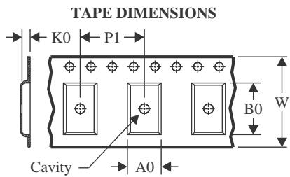
| A0 | Dimension designed to accommodate the component width |
| B0 | Dimension designed to accommodate the component length |
| K0 | Dimension designed to accommodate the component thickness |
| W | Overall width of the carrier tape |
| P1 | Pitch between successive cavity centers |
Reel Width (W1)
QUADRANT ASSIGNMENTS FOR PIN 1 ORIENTATION IN TAPE
*All dimensions are nomina
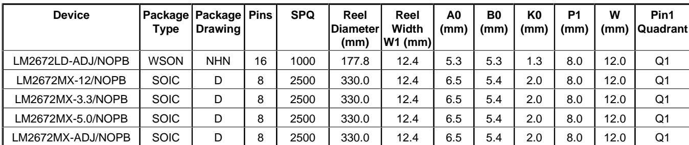
| Device | Package Type | Package Drawing | Pins | SPQ | Reel Diameter (mm) | Reel Width W1 (mm) | A0 (mm) | B0 (mm) | K0 (mm) | P1 (mm) | W (mm) | Pin1 Quadrant |
| LM2672LD-ADJ/NOPB | WSON | NHN | 16 | 1000 | 177.8 | 12.4 | 5.3 | 5.3 | 1.3 | 8.0 | 12.0 | Q1 |
| LM2672MX-12/NOPB | SOIC | D | 8 | 2500 | 330.0 | 12.4 | 6.5 | 5.4 | 2.0 | 8.0 | 12.0 | Q1 |
| LM2672MX-3.3/NOPB | SOIC | D | 8 | 2500 | 330.0 | 12.4 | 6.5 | 5.4 | 2.0 | 8.0 | 12.0 | Q1 |
| LM2672MX-5.0/NOPB | SOIC | D | 8 | 2500 | 330.0 | 12.4 | 6.5 | 5.4 | 2.0 | 8.0 | 12.0 | Q1 |
| LM2672MX-ADJ/NOPB | SOIC | D | 8 | 2500 | 330.0 | 12.4 | 6.5 | 5.4 | 2.0 | 8.0 | 12.0 | Q1 |

*All dimensions are nominal
| Device | Package Type | Package Drawing | Pins | SPQ | Length (mm) | Width (mm) | Height (mm) |
| LM2672LD-ADJ/NOPB | WSON | NHN | 16 | 1000 | 208.0 | 191.0 | 35.0 |
| LM2672MX-12/NOPB | SOIC | D | 8 | 2500 | 367.0 | 367.0 | 35.0 |
| LM2672MX-3.3/NOPB | SOIC | D | 8 | 2500 | 367.0 | 367.0 | 35.0 |
| LM2672MX-5.0/NOPB | SOIC | D | 8 | 2500 | 367.0 | 367.0 | 35.0 |
| LM2672MX-ADJ/NOPB | SOIC | D | 8 | 2500 | 367.0 | 367.0 | 35.0 |
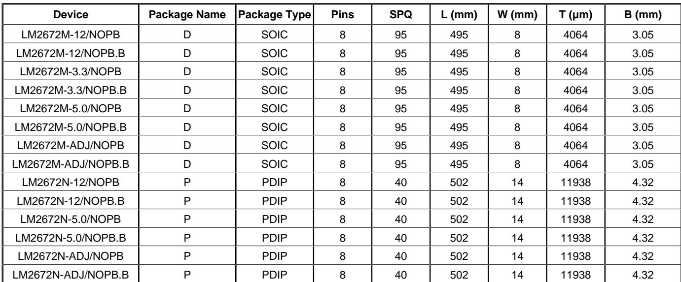
TUBE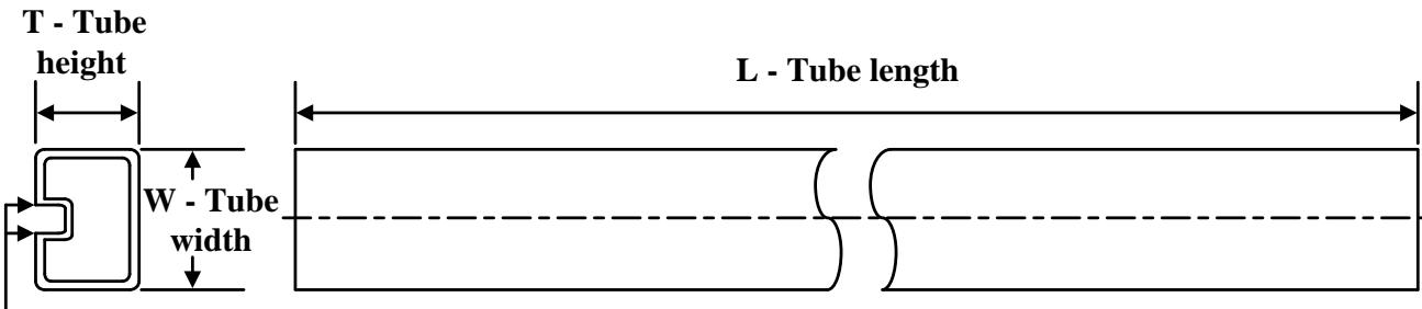
B - Alignment groove width
*All dimensions are nominal
| Device | Package Name | Package Type | Pins | SPQ | L (mm) | W (mm) | T (μm) | B (mm) |
| LM2672M-12/NOPB | D | SOIC | 8 | 95 | 495 | 8 | 4064 | 3.05 |
| LM2672M-12/NOPB.B | D | SOIC | 8 | 95 | 495 | 8 | 4064 | 3.05 |
| LM2672M-3.3/NOPB | D | SOIC | 8 | 95 | 495 | 8 | 4064 | 3.05 |
| LM2672M-3.3/NOPB.B | D | SOIC | 8 | 95 | 495 | 8 | 4064 | 3.05 |
| LM2672M-5.0/NOPB | D | SOIC | 8 | 95 | 495 | 8 | 4064 | 3.05 |
| LM2672M-5.0/NOPB.B | D | SOIC | 8 | 95 | 495 | 8 | 4064 | 3.05 |
| LM2672M-ADJ/NOPB | D | SOIC | 8 | 95 | 495 | 8 | 4064 | 3.05 |
| LM2672M-ADJ/NOPB.B | D | SOIC | 8 | 95 | 495 | 8 | 4064 | 3.05 |
| LM2672N-12/NOPB | P | PDIP | 8 | 40 | 502 | 14 | 11938 | 4.32 |
| LM2672N-12/NOPB.B | P | PDIP | 8 | 40 | 502 | 14 | 11938 | 4.32 |
| LM2672N-5.0/NOPB | P | PDIP | 8 | 40 | 502 | 14 | 11938 | 4.32 |
| LM2672N-5.0/NOPB.B | P | PDIP | 8 | 40 | 502 | 14 | 11938 | 4.32 |
| LM2672N-ADJ/NOPB | P | PDIP | 8 | 40 | 502 | 14 | 11938 | 4.32 |
| LM2672N-ADJ/NOPB.B | P | PDIP | 8 | 40 | 502 | 14 | 11938 | 4.32 |

RECOMMENDED LAND PATTERN 1:1 RATIO WITH PKG SOLDER PADS
DIMENSIONS ARE IN MILLIMETERS
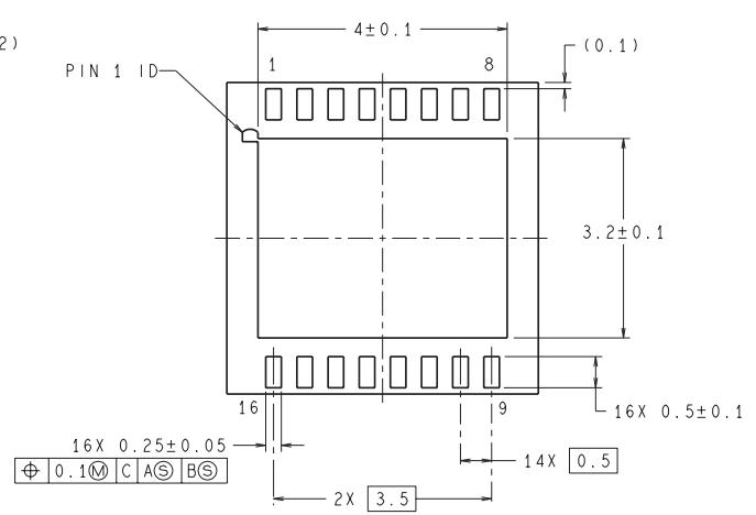
LDA16A (REV A)
SMALL OUTLINE INTEGRATED CIRCUIT
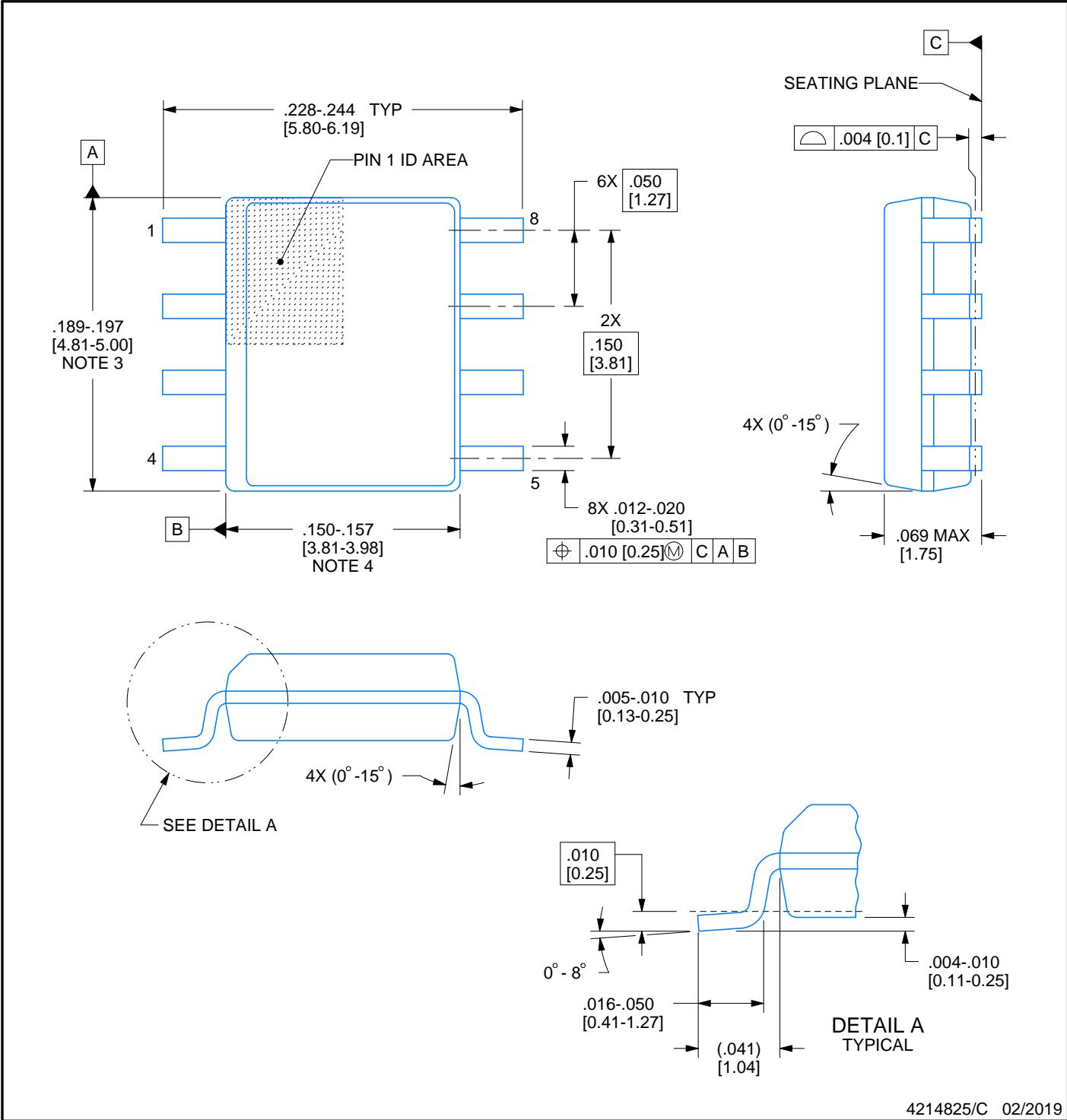
NOTES:
SMALL OUTLINE INTEGRATED CIRCUIT
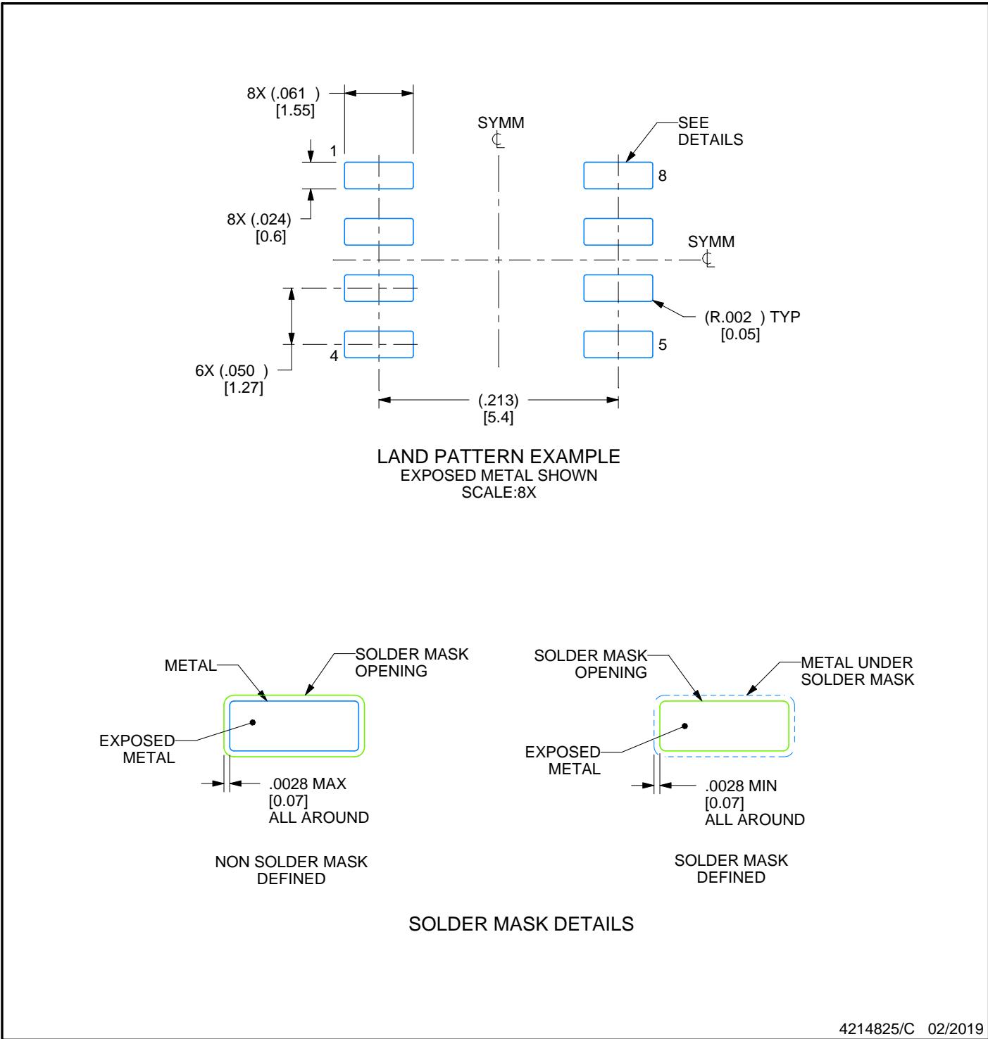
NOTES: (continued)
Publication IPC-7351 may have alternate designs.
Solder mask tolerances between and around signal pads can vary based on board fabrication site.
SMALL OUTLINE INTEGRATED CIRCUIT
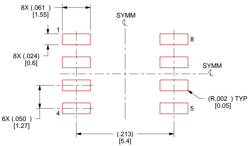
SOLDER PASTE EXAMPLE BASED ON .005 INCH [0.125 MM] THICK STENCIL SCALE:8X
4214825/C 02/2019
NOTES: (continued)
Laser cutting apertures with trapezoidal walls and rounded corners may offer better paste release. IPC-7525 may have alternate design recommendations.
Board assembly site may have different recommendations for stencil design.
P (R-PDIP-T8)
PLASTIC DUAL-IN-LINE PACKAGE
NOTES: A. All linear dimensions are in inches (millimeters)
B. This drawing is subject to change without notice.
C. Falls within JEDEC MS-001 variation BA.
Figures and diagrams from the PDF
Preview the extracted datasheet assets and open any image in a separate tab for closer inspection.
















Use this datasheet from any agent
Send the page, markdown, chunks, or search endpoint to ChatGPT, Claude, embedr-app, or your own tooling.