
ESP32-C3-DevKitM-1 Shield Footprint
Carrier/shield PCB footprint for the Espressif ESP32-C3-DevKitM-1 development board, modeling the two 15-pin 2.54 mm side headers. This is the assembled board mating footprint, not the bare ESP32-C3 MCU or ESP32-C3-MINI module.
ESP32-C3
esp-dev-kits Documentation
Table of contents
Table of contents
1 ESP32-C3-DevKitC-02
1.1 ESP32-C3-DevKitC-02
1.1.1 Getting Started
1.1.2 Hardware Reference
1.1.3 Hardware Revision Details
1.1.4 Related Documents
2 ESP32-C3-DevKitM-1
2.1 ESP32-C3-DevKitM-1
2.1.1 Getting Started
2.1.2 Hardware Reference
2.1.3 Hardware Revision Details
2.1.4 Related Documents
3 ESP32-C3-LCDkit
3.1 ESP32-C3-LCDkit
3.1.1 Board Overview
3.1.2 Start Application Development
3.1.3 Hardware Reference
3.1.4 Hardware Revision Details
3.1.5 Sample Request
3.1.6 Related Documents
4 ESP32-C3-DevKit-RUST-2
4.1 ESP32-C3-DevKit-RUST-2
4.1.1 Getting Started
4.1.2 Hardware Reference
4.1.3 Hardware Revision Details
4.1.4 Related Documents
5 Related Documentation and Resources
5.1 Related Documentation
5.2 Developer Zone
5.3 Products
5.4 Contact Us
6 Disclaimer and Copyright Notice
This document provides detailed user guides and examples for ESP32-C3 series development boards.
Note: For the full list of Espressif development boards, please go to ESP DevKits.
Chapter 1
ESP32-C3-DevKitC-02
ESP32-C3-DevKitC-02 is an entry-level development board based on ESP32-C3-WROOM-02 or ESP32-C3- WROOM-02U, general-purpose modules with 4 MB SPI flash. This board integrates complete Wi-Fi and Bluetooth® Low Energy functions.
1.1 ESP32-C3-DevKitC-02
This user guide will help you get started with ESP32-C3-DevKitC-02 and will also provide more in-depth information.
ESP32-C3-DevKitC-02 is an entry-level development board based on ESP32-C3-WROOM-02 or ESP32-C3- WROOM-02U, general-purpose modules with 4 MB SPI flash. This board integrates complete Wi-Fi and Bluetooth® Low Energy functions.
Most of the I/O pins are broken out to the pin headers on both sides for easy interfacing. Developers can either connect peripherals with jumper wires or mount ESP32-C3-DevKitC-02 on a breadboard.
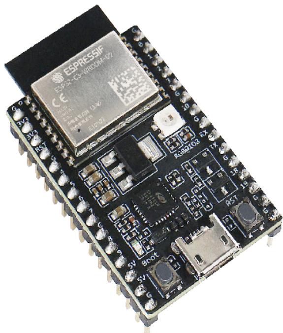
Fig. 1: ESP32-C3-DevKitC-02
The document consists of the following major sections:
• Getting Started: Overview of ESP32-C3-DevKitC-02 and hardware/software setup instructions to get started.
• Hardware Reference: More detailed information about the ESP32-C3-DevKitC-02’s hardware.
• Hardware Revision Details: Revision history, known issues, and links to user guides for previous versions (if any) of ESP32-C3-DevKitC-02.
• Related Documents: Links to related documentation.
1.1.1 Getting Started
This section provides a brief introduction of ESP32-C3-DevKitC-02, instructions on how to do the initial hardware setup and how to flash firmware onto it.
Description of Components
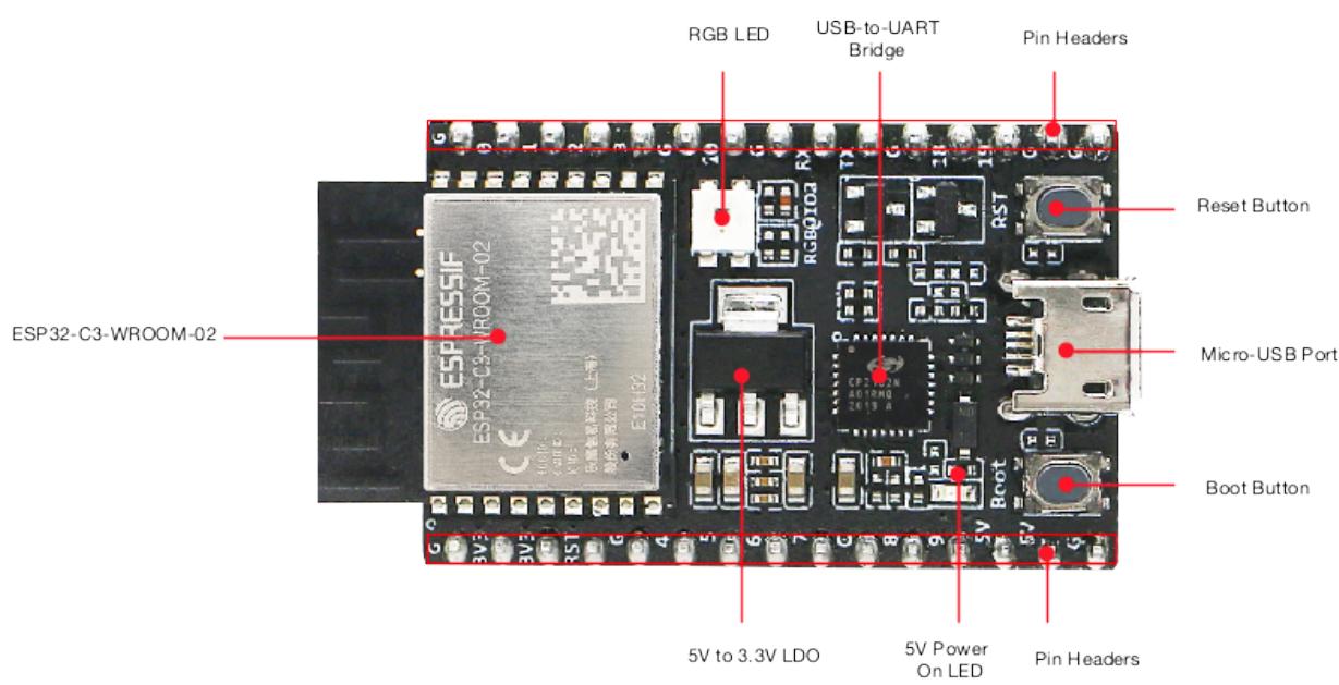
Fig. 2: ESP32-C3-DevKitC-02 (with the ESP32-C3-WROOM-02 module) - front
The key components of the board are described in a counter-clockwise direction.
| Key Component | Description |
| ESP32-C3-WROOM-02 or ESP32-C3-WROOM-02U | ESP32-C3-WROOM-02 and ESP32-C3-WROOM-02U are powerful and general-purpose Espressif modules that offer Wi-Fi and Bluetooth Low Energy coexistence. ESP32-C3-WROOM-02 has a PCB antenna, while ESP32-C3-WROOM-02U has an external antenna connector. They both integrate a 4 MB SPI flash. |
| 5 V to 3.3 V LDO | Power regulator that converts a 5 V supply into a 3.3 V output. |
| 5 V Power On LED | Turns on when the USB power is connected to the board. |
| Pin Headers | All available GPIO pins (except for the SPI bus for flash) are broken out to the pin headers on the board. For details, please see Header Block. |
| Boot Button | Download button. Holding down Boot and then pressing Reset initiates Firmware Download mode for downloading firmware through the serial port. |
| Micro-USB Port | USB interface. Power supply for the board as well as the communication interface between a computer and the ESP32-C3 chip. |
| Reset Button | Press this button to restart the system. |
| USB-to-UART Bridge | Single USB-to-UART bridge chip provides transfer rates up to 3 Mbps. |
| RGB LED | Addressable RGB LED, driven by GPIO8. |
Start Application Development
Before powering up your ESP32-C3-DevKitC-02, please make sure that it is in good condition with no obvious signs of damage.
Required Hardware
• ESP32-C3-DevKitC-02
• USB 2.0 cable (Standard-A to Micro-B)
• Computer running Windows, Linux, or macOS
Note: Be sure to use an appropriate USB cable. Some cables are for charging only and do not provide the needed data lines nor work for programming the boards.
Software Setup Please proceed to ESP-IDF Get Started, which will quickly help you set up the development environment then flash an application example onto your board.
Contents and Packaging
Retail Orders If you order a few samples, each ESP32-C3-DevKitC-02 comes in an individual package in either antistatic bag or any packaging depending on your retailer.
For retail orders, please go to https://www.espressif.com/en/contact-us/get-samples.
Wholesale Orders If you order in bulk, the boards come in large cardboard boxes.
For wholesale orders, please check Espressif Product Ordering Information (PDF)
1.1.2 Hardware Reference
Block Diagram
The block diagram below shows the components of ESP32-C3-DevKitC-02 and their interconnections.
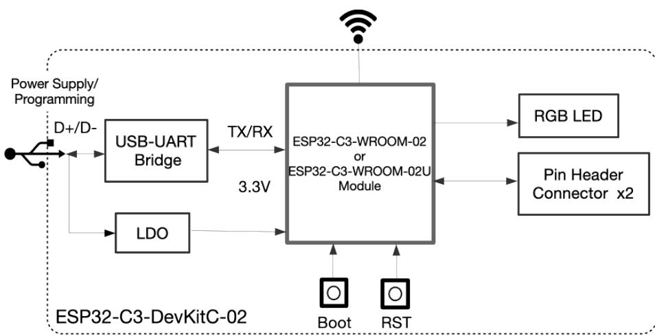
Fig. 3: ESP32-C3-DevKitC-02 (click to enlarge)
Power Supply Options There are three mutually exclusive ways to provide power to the board:
• Micro-USB Port, default power supply
• 5V and GND pin headers
• 3V3 and GND pin headers
It is recommended to use the first option: Micro-USB Port.
Header Block
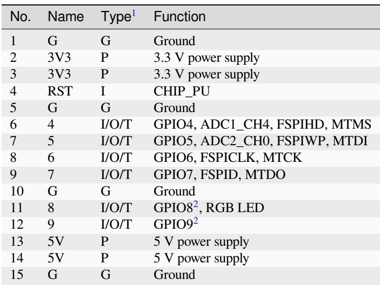
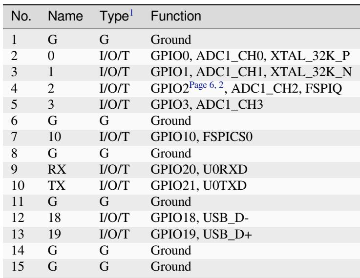
The two tables below provide the Name and Function of the pin headers on both sides of the board (J1 and J3). The pin header names are shown in ESP32-C3-DevKitC-02 (with the ESP32-C3-WROOM-02 module) - front. The numbering is the same as in the ESP32-C3-DevKitC-02 Schematic (PDF).
J1
| No. | Name | Type $^{1}$ | Function |
| 1 | G | G | Ground |
| 2 | 3V3 | P | 3.3 V power supply |
| 3 | 3V3 | P | 3.3 V power supply |
| 4 | RST | I | CHIP_PU |
| 5 | G | G | Ground |
| 6 | 4 | I/O/T | GPIO4, ADC1_CH4, FSPIHD, MTMS |
| 7 | 5 | I/O/T | GPIO5, ADC2_CH0, FSPIWP, MTDI |
| 8 | 6 | I/O/T | GPIO6, FSPICLK, MTCK |
| 9 | 7 | I/O/T | GPIO7, FSPID, MTDO |
| 10 | G | G | Ground |
| 11 | 8 | I/O/T | GPIO8 $^{2}$ , RGB LED |
| 12 | 9 | I/O/T | GPIO9 $^{2}$ |
| 13 | 5V | P | 5 V power supply |
| 14 | 5V | P | 5 V power supply |
| 15 | G | G | Ground |
J3
| No. | Name | Type1 | Function |
| 1 | G | G | Ground |
| 2 | 0 | I/O/T | GPIO0, ADC1_CH0, XTAL_32K_P |
| 3 | 1 | I/O/T | GPIO1, ADC1_CH1, XTAL_32K_N |
| 4 | 2 | I/O/T | GPIO2Page 6, 2, ADC1_CH2, FSPIQ |
| 5 | 3 | I/O/T | GPIO3, ADC1_CH3 |
| 6 | G | G | Ground |
| 7 | 10 | I/O/T | GPIO10, FSPICS0 |
| 8 | G | G | Ground |
| 9 | RX | I/O/T | GPIO20, U0RXD |
| 10 | TX | I/O/T | GPIO21, U0TXD |
| 11 | G | G | Ground |
| 12 | 18 | I/O/T | GPIO18, USB_D- |
| 13 | 19 | I/O/T | GPIO19, USB_D+ |
| 14 | G | G | Ground |
| 15 | G | G | Ground |
ESP32-C3-DevKitC-02

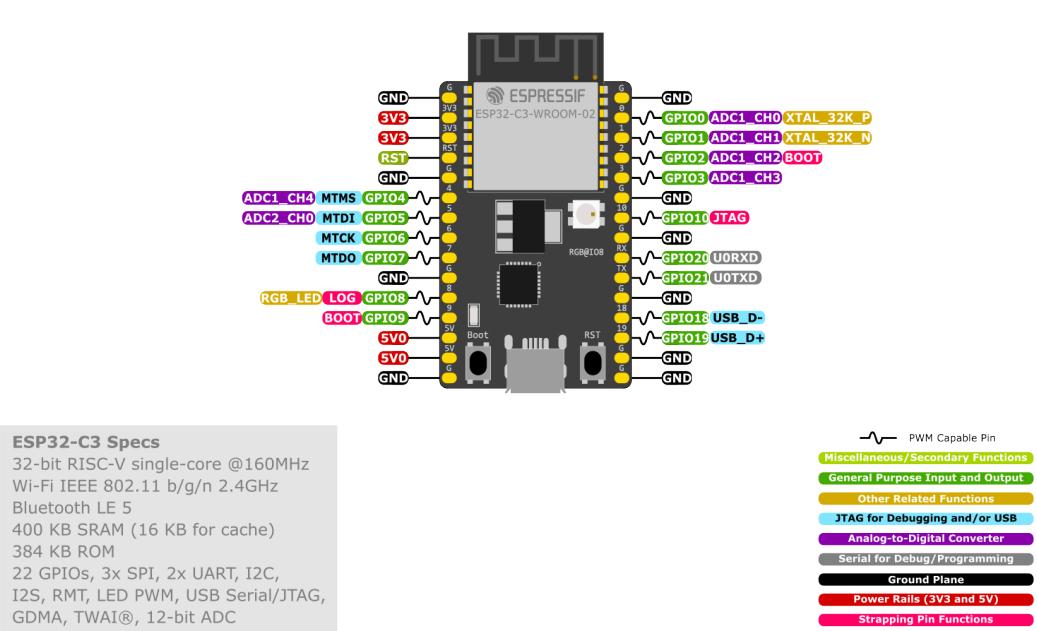
Fig. 4: ESP32-C3-DevKitC-02 Pin Layout (with the ESP32-C3-WROOM-02 module, click to enlarge)
Pin Layout
1.1.3 Hardware Revision Details
No previous versions available.
1.1.4 Related Documents
• ESP32-C3 Datasheet (PDF)
• ESP32-C3-WROOM-02 & ESP32-C3-WROOM-02U Datasheet (PDF)
• ESP32-C3-DevKitC-02 Schematic (PDF)
• ESP32-C3-DevKitC-02 PCB Layout (PDF)
• ESP32-C3-DevKitC-02 Dimensions (PDF)
• ESP32-C3-DevKitC-02 Dimensions source file (DXF) - You can view it with Autodesk Viewer online
For further design documentation for the board, please contact us at sales@espressif.com.
ESP32-C3-DevKitM-1
ESP32-C3-DevKitM-1 is an entry-level development board based on ESP32-C3-MINI-1 or ESP32-C3-MINI-1U, modules named for its small size. This board integrates complete Wi-Fi and Bluetooth® Low Energy functions.
2.1 ESP32-C3-DevKitM-1
This user guide will help you get started with ESP32-C3-DevKitM-1 and will also provide more in-depth information.
ESP32-C3-DevKitM-1 is an entry-level development board based on ESP32-C3-MINI-1 or ESP32-C3-MINI-1U modules, which are named for their compact size. This board integrates complete Wi-Fi and Bluetooth® Low Energy functions.
Most of the I/O pins on the module are broken out to the pin headers on both sides of this board for easy interfacing. Developers can either connect peripherals with jumper wires or mount ESP32-C3-DevKitM-1 on a breadboard.
The document consists of the following major sections:
• Getting Started: Overview of ESP32-C3-DevKitM-1 and hardware/software setup instructions to get started.
• Hardware Reference: More detailed information about the ESP32-C3-DevKitM-1’s hardware.
• Hardware Revision Details: Revision history, known issues, and links to user guides for previous versions (if any) of ESP32-C3-DevKitM-1.
• Related Documents: Links to related documentation.
2.1.1 Getting Started
This section provides a brief introduction of ESP32-C3-DevKitM-1, instructions on how to do the initial hardware setup and how to flash firmware onto it.
Description of Components
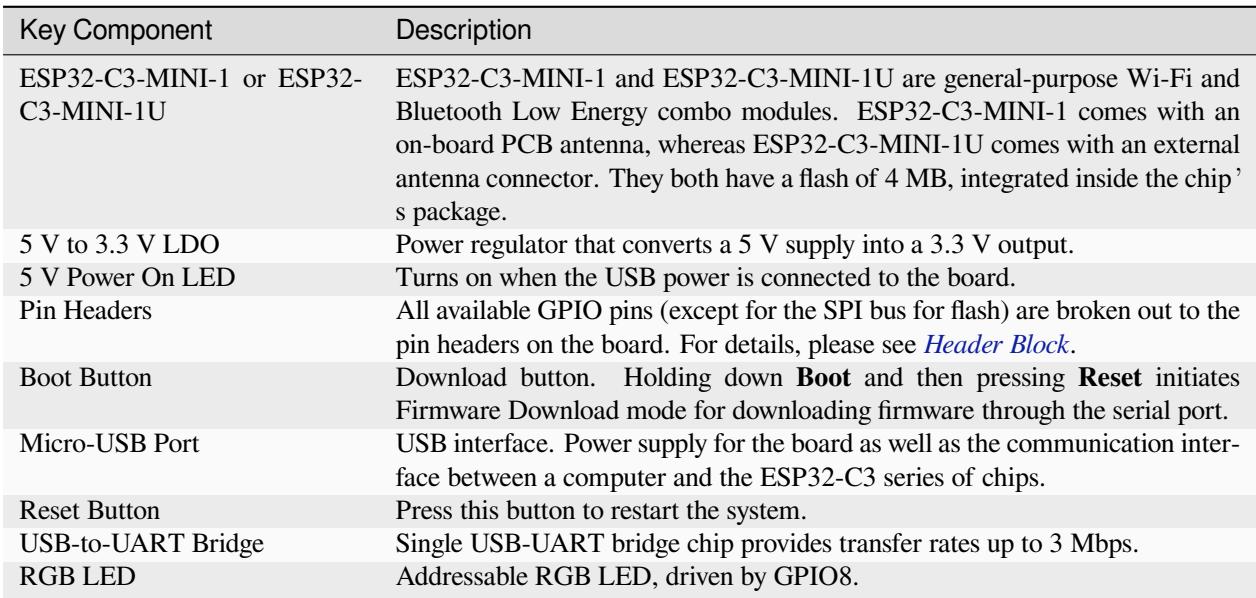
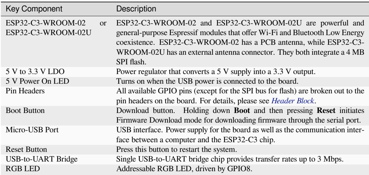
The key components of the board are described in a counter-clockwise direction.
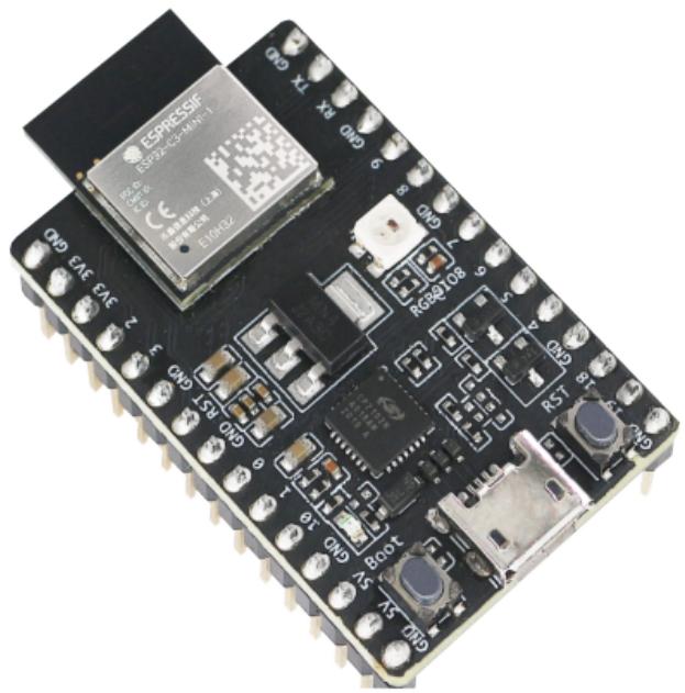
Fig. 1: ESP32-C3-DevKitM-1
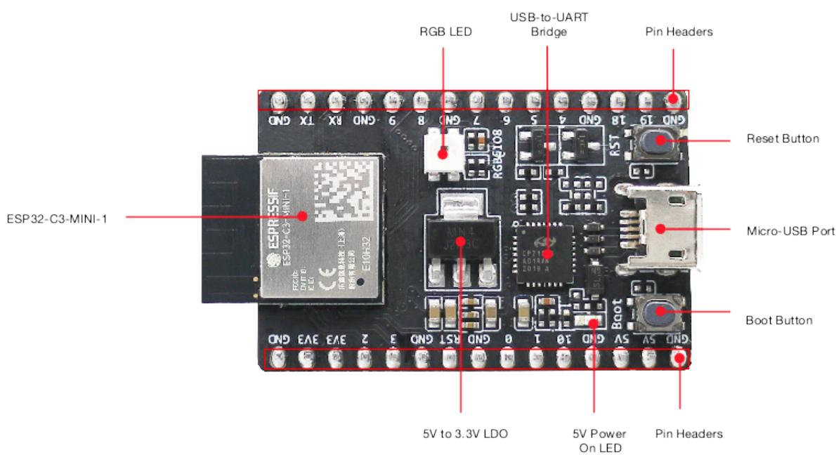
Fig. 2: ESP32-C3-DevKitM-1 (with the ESP32-C3-MINI-1 module) - front
| Key Component | Description |
| ESP32-C3-MINI-1 or ESP32-C3-MINI-1U | ESP32-C3-MINI-1 and ESP32-C3-MINI-1U are general-purpose Wi-Fi and Bluetooth Low Energy combo modules. ESP32-C3-MINI-1 comes with an on-board PCB antenna, whereas ESP32-C3-MINI-1U comes with an external antenna connector. They both have a flash of 4 MB, integrated inside the chip's package. |
| 5 V to 3.3 V LDO | Power regulator that converts a 5 V supply into a 3.3 V output. |
| 5 V Power On LED | Turns on when the USB power is connected to the board. |
| Pin Headers | All available GPIO pins (except for the SPI bus for flash) are broken out to the pin headers on the board. For details, please see Header Block. |
| Boot Button | Download button. Holding down Boot and then pressing Reset initiates Firmware Download mode for downloading firmware through the serial port. |
| Micro-USB Port | USB interface. Power supply for the board as well as the communication interface between a computer and the ESP32-C3 series of chips. |
| Reset Button | Press this button to restart the system. |
| USB-to-UART Bridge | Single USB-UART bridge chip provides transfer rates up to 3 Mbps. |
| RGB LED | Addressable RGB LED, driven by GPIO8. |
Start Application Development
Before powering up your ESP32-C3-DevKitM-1, please make sure that it is in good condition with no obvious signs of damage.
Required Hardware
• ESP32-C3-DevKitM-1
• USB 2.0 cable (Standard-A to Micro-B)
• Computer running Windows, Linux, or macOS
Note: Be sure to use an appropriate USB cable. Some cables are for charging only and do not provide the needed data lines nor work for programming the boards.
Software Setup Please proceed to ESP-IDF Get Started, which will quickly help you set up the development environment then flash an application example onto your board.
Contents and Packaging
Retail Orders If you order one or several samples, each ESP32-C3-DevKitM-1 comes in an individual package in either antistatic bag or any packaging depending on your retailer.
For retail orders, please go to https://www.espressif.com/en/contact-us/get-samples.
Wholesale Orders If you order in bulk, the boards come in large cardboard boxes.
For wholesale orders, please check Espressif Product Ordering Information (PDF)
2.1.2 Hardware Reference
Block Diagram
The block diagram below shows the components of ESP32-C3-DevKitM-1 and their interconnections.
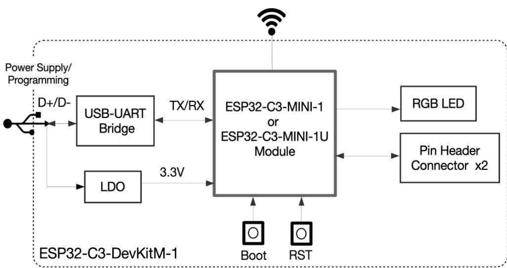
Fig. 3: ESP32-C3-DevKitM-1 (click to enlarge)
Power Supply Options There are three mutually exclusive ways to provide power to the board:
• Micro-USB Port, default power supply
• 5V and GND pin headers
• 3V3 and GND pin headers
It is recommended to use the first option: Micro-USB Port.
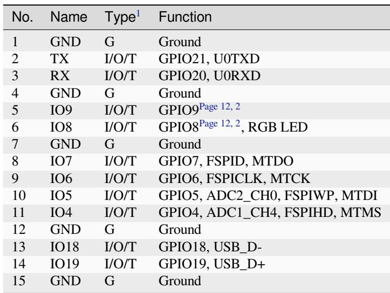
Header Block
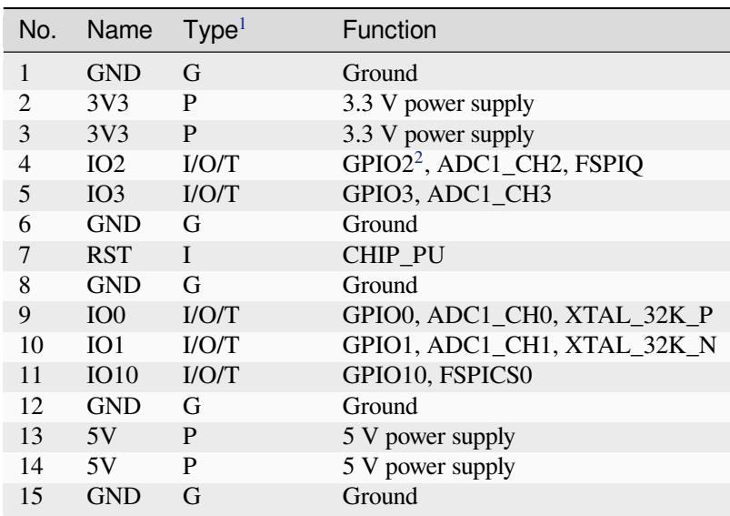
The two tables below provide the Name and Function of the pin headers on both sides of the board (J1 and J3). The pin header names are shown in ESP32-C3-DevKitM-1 (with the ESP32-C3-MINI-1 module) - front. The numbering is the same as in the ESP32-C3-DevKitM-1 Schematic (PDF).
J1
| No. | Name | Type $^{1}$ | Function |
| 1 | GND | G | Ground |
| 2 | 3V3 | P | 3.3 V power supply |
| 3 | 3V3 | P | 3.3 V power supply |
| 4 | IO2 | I/O/T | GPIO2 $^{2}$ , ADC1_CH2, FSPIQ |
| 5 | IO3 | I/O/T | GPIO3, ADC1_CH3 |
| 6 | GND | G | Ground |
| 7 | RST | I | CHIP_PU |
| 8 | GND | G | Ground |
| 9 | IO0 | I/O/T | GPIO0, ADC1_CH0, XTAL_32K_P |
| 10 | IO1 | I/O/T | GPIO1, ADC1_CH1, XTAL_32K_N |
| 11 | IO10 | I/O/T | GPIO10, FSPICS0 |
| 12 | GND | G | Ground |
| 13 | 5V | P | 5 V power supply |
| 14 | 5V | P | 5 V power supply |
| 15 | GND | G | Ground |
J3
| No. | Name | Type1 | Function |
| 1 | GND | G | Ground |
| 2 | TX | I/O/T | GPIO21, U0TXD |
| 3 | RX | I/O/T | GPIO20, U0RXD |
| 4 | GND | G | Ground |
| 5 | IO9 | I/O/T | GPIO9Page 12, 2 |
| 6 | IO8 | I/O/T | GPIO8Page 12, 2, RGB LED |
| 7 | GND | G | Ground |
| 8 | IO7 | I/O/T | GPIO7, FSPID, MTDO |
| 9 | IO6 | I/O/T | GPIO6, FSPICLK, MTCK |
| 10 | IO5 | I/O/T | GPIO5, ADC2_CH0, FSPIWP, MTDI |
| 11 | IO4 | I/O/T | GPIO4, ADC1_CH4, FSPIHD, MTMS |
| 12 | GND | G | Ground |
| 13 | IO18 | I/O/T | GPIO18, USB_D- |
| 14 | IO19 | I/O/T | GPIO19, USB_D+ |
| 15 | GND | G | Ground |
ESP32-C3-DevKitM-1

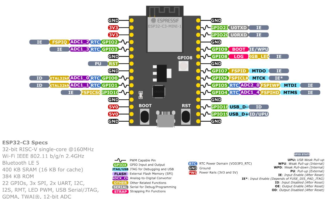
Fig. 4: ESP32-C3-DevKitM-1 Pin Layout (with the ESP32-C3-MINI-1 module, click to enlarge)
Pin Layout
2.1.3 Hardware Revision Details
No previous versions available.
2.1.4 Related Documents
• ESP32-C3 Datasheet (PDF)
• ESP32-C3-MINI-1 & ESP32-C3-MINI-1U Datasheet (PDF)
• ESP32-C3-DevKitM-1 Schematic (PDF)
• ESP32-C3-DevKitM-1 PCB Layout (PDF)
• ESP32-C3-DevKitM-1 Dimensions (PDF)
• ESP32-C3-DevKitM-1 Dimensions source file (DXF)
For further design documentation for the board, please contact us at sales@espressif.com.
ESP32-C3-LCDkit
ESP32-C3-LCDkit is a development board designed for wildlife protection. It is used to evaluate and verify the application of the ESP32-C3 screen. And it is composed of mainboard and subboard.
3.1 ESP32-C3-LCDkit
This user guide will help you get started with ESP32-C3-LCDkit and will also provide more in-depth information.
The document consists of the following sections:
• Board Overview: Overview of the board hardware/software.
• Start Application Development: How to set up hardware/software to develop applications.
• Hardware Reference: More detailed information about the board’s hardware.
• Hardware Revision Details: This is the first revision of this board released.
• Sample Request: How to get a sample board.
• Related Documents: Links to related documentation.
3.1.1 Board Overview
ESP32-C3-LCDkit is an ESP32-C3-based evaluation development board with an SPI interface display. It also has an integrated rotary encoder switch and features screen interaction. Due to its low cost, low power consumption, and high performance, ESP32-C3 satisfies the basic GUI interaction needs, gaining ground in scenarios with small screen sizes.
Feature List
The main features of the board are listed below:
• Module Embedded: ESP32-C3-MINI-1 module with 4 MB flash and 400 KB SRAM
• Display: Compatibility with various subboards and support for displays with I2C and SPI interfaces. Please refer to LCD Subboards for more information
• Rotary Encoder Switch: Key switches and 360° rotation for on-screen GUI control
• Infrared module: Infrared transmitter and infrared receiver for infrared wireless control
• Audio: On-board audio amplifier and speaker for audio playback
• USB: USB Type-C download/debug
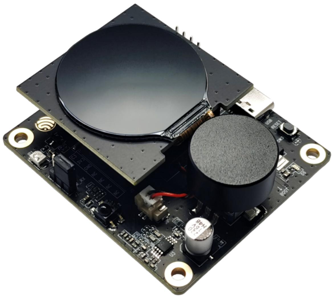
Fig. 1: ESP32-C3-LCDkit with ESP32-C3-MINI-1 Module
Block Diagram
The block diagram below shows the components of ESP32-C3-LCDkit and their interconnections.
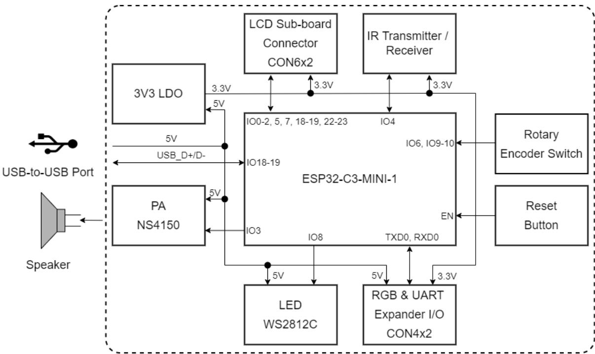
Fig. 2: ESP32-C3-LCDkit Block Diagram (Click to Enlarge)
Description of Components
ESP32-C3-LCDkit is a development board designed for wildlife protection. It contains a mainboard and a subboard.
Mainboard ESP32-C3-LCDkit_MB is the core of the kit, which integrates the ESP32-C3-MINI-1 module and provides ports for connection to the LCD subboard.
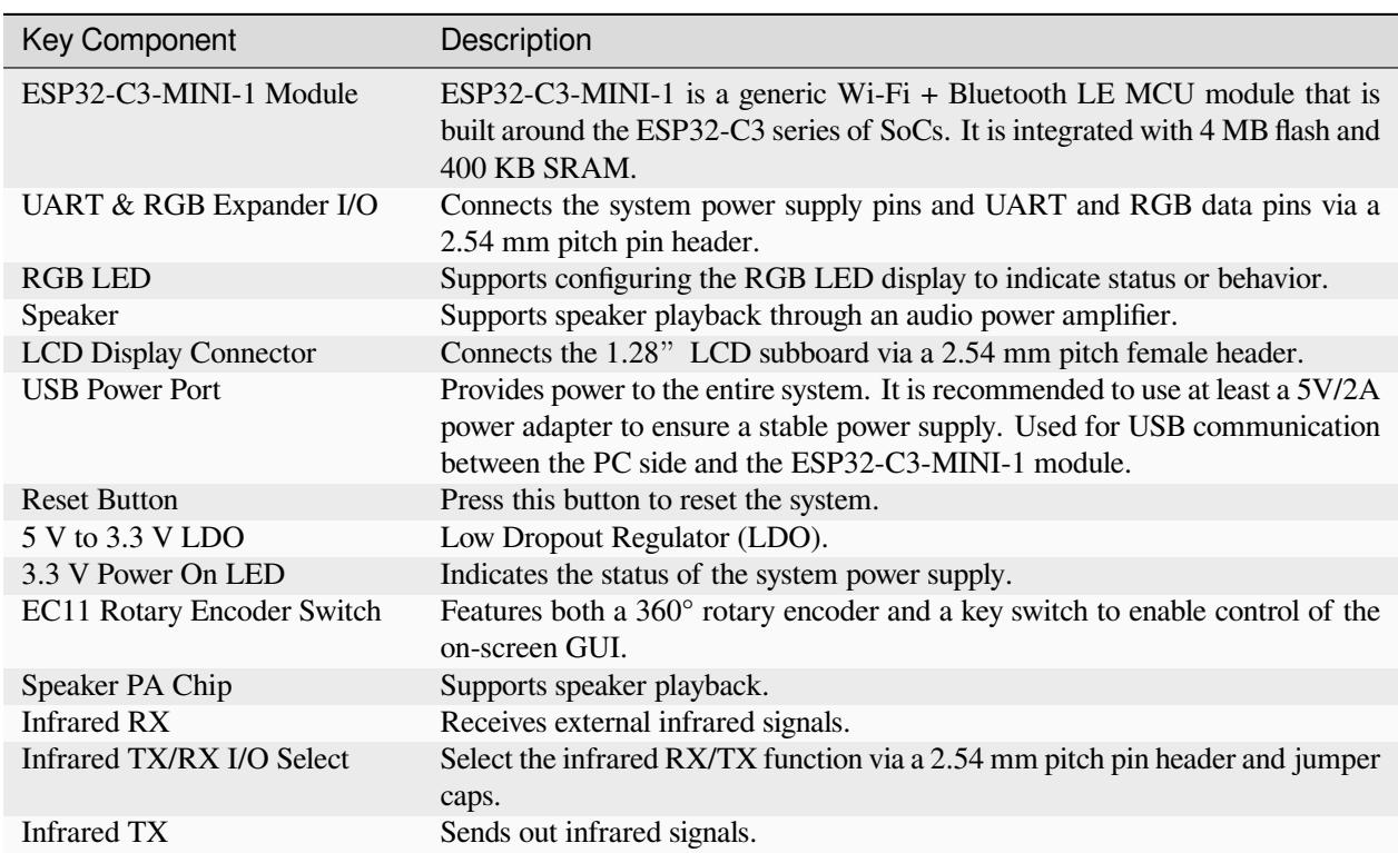
The key components of the board are described in a clockwise direction.
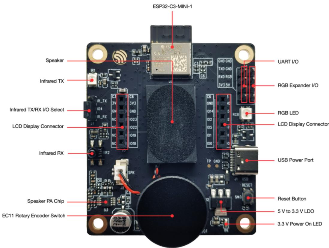
Fig. 3: ESP32-C3-LCDkit - Front (Click to Enlarge)
| Key Component | Description |
| ESP32-C3-MINI-1 Module | ESP32-C3-MINI-1 is a generic Wi-Fi + Bluetooth LE MCU module that is built around the ESP32-C3 series of SoCs. It is integrated with 4 MB flash and 400 KB SRAM. |
| UART & RGB Expander I/O | Connects the system power supply pins and UART and RGB data pins via a 2.54 mm pitch pin header. |
| RGB LED | Supports configuring the RGB LED display to indicate status or behavior. |
| Speaker | Supports speaker playback through an audio power amplifier. |
| LCD Display Connector | Connects the 1.28” LCD subboard via a 2.54 mm pitch female header. |
| USB Power Port | Provides power to the entire system. It is recommended to use at least a 5V/2A power adapter to ensure a stable power supply. Used for USB communication between the PC side and the ESP32-C3-MINI-1 module. |
| Reset Button | Press this button to reset the system. |
| 5 V to 3.3 V LDO | Low Dropout Regulator (LDO). |
| 3.3 V Power On LED | Indicates the status of the system power supply. |
| EC11 Rotary Encoder Switch | Features both a 360° rotary encoder and a key switch to enable control of the on-screen GUI. |
| Speaker PA Chip | Supports speaker playback. |
| Infrared RX | Receives external infrared signals. |
| Infrared TX/RX I/O Select | Select the infrared RX/TX function via a 2.54 mm pitch pin header and jumper caps. |
| Infrared TX | Sends out infrared signals. |
LCD Subboards The ESP32-C3-LCDkit_DB subboard supports a 1.28”LCD screen with SPI interface and 240x240 resolution. The driver chip used for this screen is GC9A01.
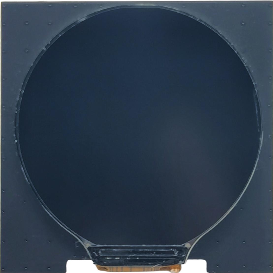
Fig. 4: ESP32-C3-LCDkit_DB - Front (Click to Enlarge)
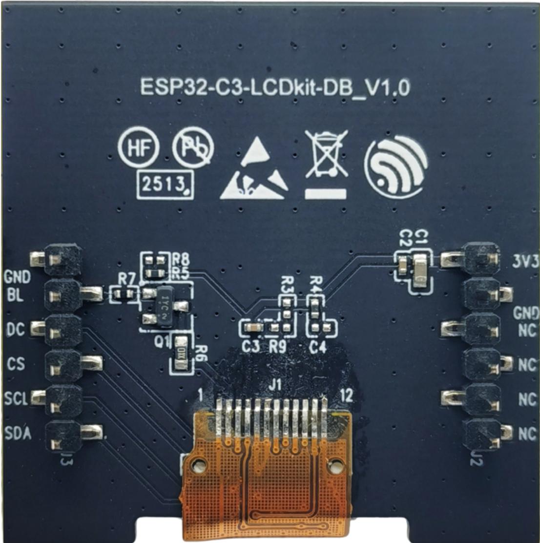
Fig. 5: ESP32-C3-LCDkit_DB - Back (Click to Enlarge)
Software Support
The ESP32-C3-LCDkit development framework is ESP-IDF. ESP-IDF is a FreeRTOS-based SoC development framework with a bunch of components including LCD, ADC, RMT, and SPI. An example is provided for ESP32- C3-LCDkit under the folder Examples . You can configure project options by entering idf.py menuconfig in the example directory.
Application Examples
The following application examples are available for ESP32-C3-LCDkit:
• Knob Panel Example - Demonstrates a GUI demo for a knob panel with voice playback functionality, providing a reference for developing similar applications using the ESP32-C3-LCDkit.
For more examples and the latest updates, please refer to the examples folder.
To explore the application examples or to develop your own, please follow the steps outlined in the Start Application Development section.
3.1.2 Start Application Development
This section provides instructions on how to do hardware and software setup and flash firmware onto the board to develop your own application.
Required Hardware
• 1 x ESP32-C3-LCDkit_MB
• 1 x LCD subboard
• 1 x USB 2.0 cable (standard Type-A to Type-C)
• 1 x PC (Windows, Linux, or macOS)
Note: Please make sure to use the appropriate USB cable. Some cables can only be used for charging, not for data transfer or program flashing.
Hardware Setup
Prepare the board for loading of the first sample application:
Connect the LCD subboard to the LCD Display Connector.
Plug in the USB cable to connect the PC with the board.
The LCD lights up and you can now control GUI through the rotary encoder switch.
Now the board is ready for software setup.
Software Setup
To learn how to quickly set up your development environment, please go to Get Started > Installation.
For more software information on developing applications, please go to Software Support.
3.1.3 Hardware Reference
This section provides more detailed information about the board’s hardware.
GPIO Allocation
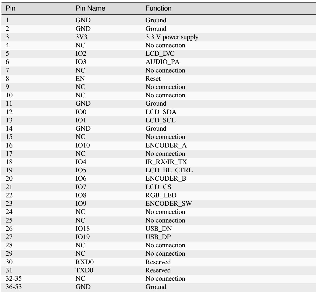
The table below provides the allocation of GPIOs exposed on terminals of ESP32-C3-MINI-1 module to control specific components or functions of the board.
Table 1: ESP32-C3-MINI-1 GPIO Allocation
| Pin | Pin Name | Function |
| 1 | GND | Ground |
| 2 | GND | Ground |
| 3 | 3V3 | 3.3 V power supply |
| 4 | NC | No connection |
| 5 | IO2 | LCD_D/C |
| 6 | IO3 | AUDIO_PA |
| 7 | NC | No connection |
| 8 | EN | Reset |
| 9 | NC | No connection |
| 10 | NC | No connection |
| 11 | GND | Ground |
| 12 | IO0 | LCD_SDA |
| 13 | IO1 | LCD_SCL |
| 14 | GND | Ground |
| 15 | NC | No connection |
| 16 | IO10 | ENCODER_A |
| 17 | NC | No connection |
| 18 | IO4 | IR_RX/IR_TX |
| 19 | IO5 | LCD_BL_CTRL |
| 20 | IO6 | ENCODER_B |
| 21 | IO7 | LCD_CS |
| 22 | IO8 | RGB_LED |
| 23 | IO9 | ENCODER_SW |
| 24 | NC | No connection |
| 25 | NC | No connection |
| 26 | IO18 | USB_DN |
| 27 | IO19 | USB_DP |
| 28 | NC | No connection |
| 29 | NC | No connection |
| 30 | RXD0 | Reserved |
| 31 | TXD0 | Reserved |
| 32-35 | NC | No connection |
| 36-53 | GND | Ground |
Power Distribution
The development board is powered via the USB-to-USB port:
Output system power supply:
Infrared TX/RX Select
Since the Infrared TX and Infrared RX modules share the same signal line on the chip, it is required to short-circuit specific pins in Infrared TX/RX Select Port via jumper caps to choose between the TX/RX function:
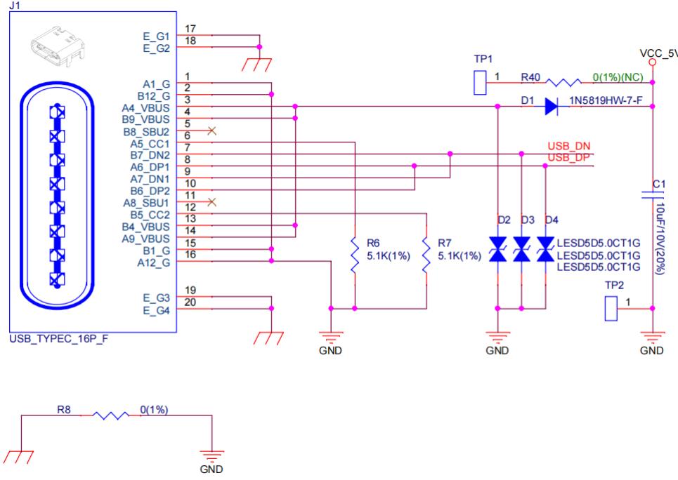
Fig. 6: ESP32-C3-LCDkit - USB-to-USB Power Supply
3V3 LDO
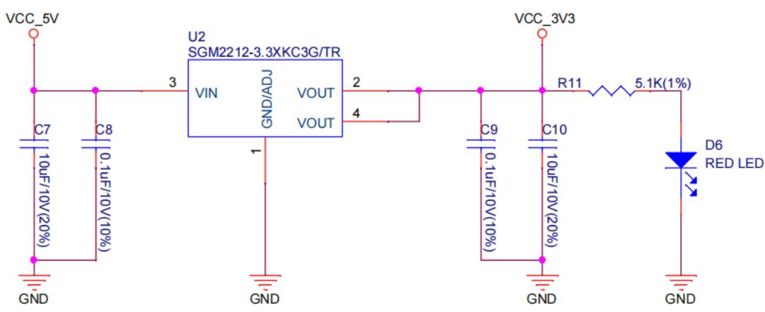
Fig. 7: ESP32-C3-LCDkit - System Power Supply
IR Receiver
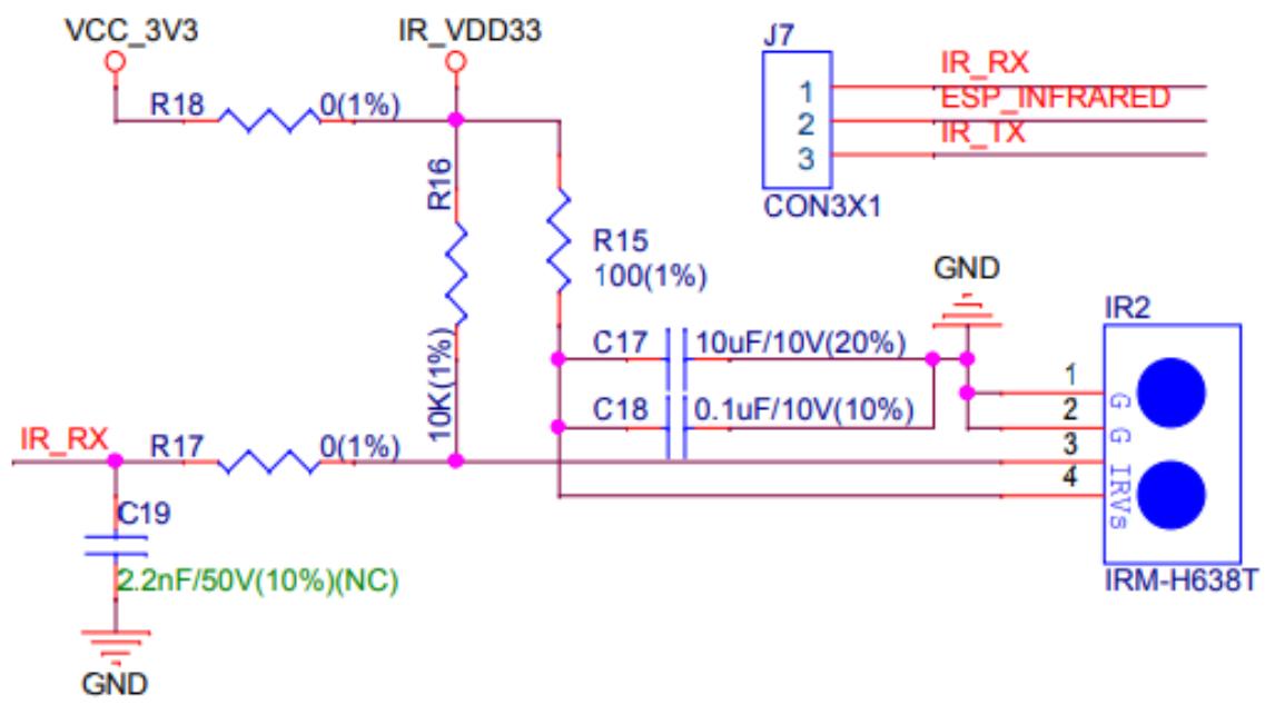
Fig. 8: ESP32-C3-LCDkit - Infrared RX Module
IR Transmitter
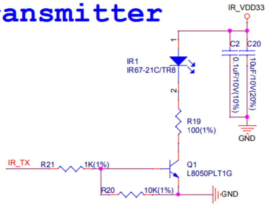
Fig. 9: ESP32-C3-LCDkit - Infrared TX Module
C6 Module Compatibility Design
ESP32-C3-LCDkit development board uses the ESP32-C3-MINI-1 module by default, with resistors R2, R4, R5, and R35 connected to the mainboard:
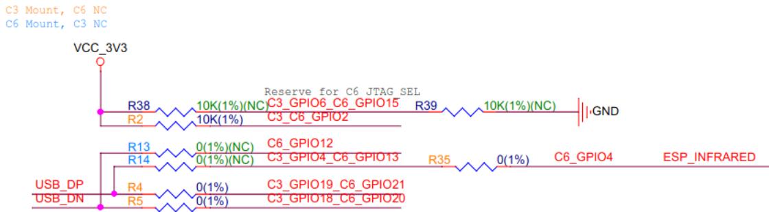
Fig. 10: ESP32-C3-LCDkit - C3/C6 Resistor Settings
The development board is also designed to be compatible with the ESP32-C6-MINI-1 module, where resistors R2, R4, R5, and R35 need to be removed and resistors R13 and R14 need to be connected.
Hardware Setup Options
Automatic Download After the development board is powered on, press the rotary encoder switch and Reset button, then release Reset first and the encoder second, to put the ESP development board into download mode.
3.1.4 Hardware Revision Details
• ESP32-C3-LCD-Ev-Board: This older-version board is an engineering sample and is minimally maintained by Espressif. For historical documentation for this board, please refer to ESP32-C3-LCD-Ev-Board User Guide.
3.1.5 Sample Request
ESP32-C3 is a cost-efective and industry-leading low-power performance solution for building rotary or small displays driven by an SPI interface. For sample requests, please contact us at sales@espressif.com.
3.1.6 Related Documents
Please download the following documents from the HTML version of esp-dev-kits Documentation.
• ESP32-C3 Datasheet
• ESP32-C3-MINI-1 Datasheet
• ESP Product Selector
• ESP32-C3-LCDkit_MB Schematics
• ESP32-C3-LCDkit_MB PCB Layout
• ESP32-C3-LCDkit_DB Schematics
• ESP32-C3-LCDkit_DB PCB Layout
• ESP32-C6-LCDkit_DB Schematics
• ESP32-C6-LCDkit_DB PCB Layout
• 1.28_TFT_240x240_SPI_Display
• Infrared Transmitter (IR67-21CTR8)
• Infrared Receiver(IRM-H638TTR2)
• Audio Amplifier (NS4150)
• RGB LED (WS2812B)
• 2415 Voice Cavity Horn
For further design documentation for the board, please contact us at sales@espressif.com.
ESP32-C3-LCD-Ev-Board
This user guide will help you get started with ESP32-C3-LCD-Ev-Board and will also provide more in-depth information.
The document consists of the following sections:
• Board Overview: Overview of the board hardware/software.
• Start Application Development: How to set up hardware/software to develop applications.
• Hardware Reference: More detailed information about the board’s hardware.
• Hardware Revision Details: This is the first revision of this board released.
• Sample Request: How to get a sample board.
• Related Documents: Links to related documentation.
Board Overview ESP32-C3-LCD-Ev-Board is an ESP32-C3-based evaluation development board with an SPI interface display. It also has an integrated rotary encoder switch and features screen interaction. Due to its low cost, low power consumption, and high performance, ESP32-C3 satisfies the basic GUI interaction needs, gaining ground in scenarios with small screen sizes.
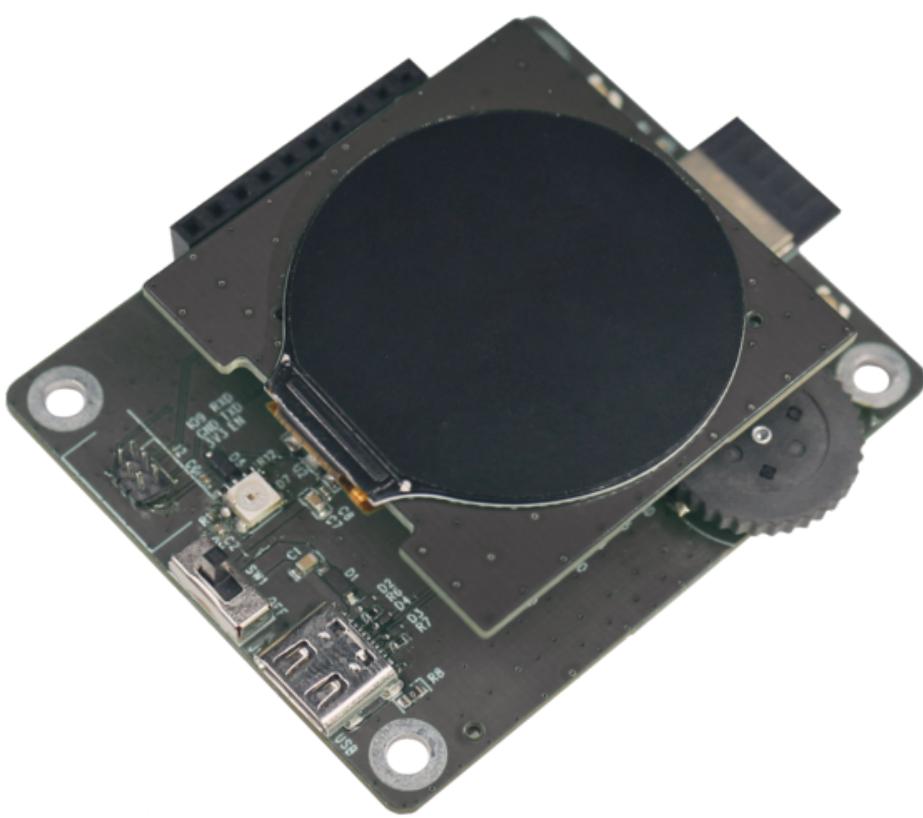
Fig. 11: ESP32-C3-LCD-Ev-Board with ESP32-C3-MINI-1 Module
Feature List The main features of the board are listed below:
• Module Embedded: ESP32-C3-MINI-1 module with 4 MB flash and 400 KB SRAM • Display: Compatibility with various subboards and support for displays with I2C and SPI interfaces. Please refer to LCD Subboards for more information
• Rotary Encoder Switch: Key switches and 360° rotation for on-screen GUI control
• USB: USB Type-C download/debug
Block Diagram The block diagram below shows the components of ESP32-C3-LCD-Ev-Board and their interconnections.
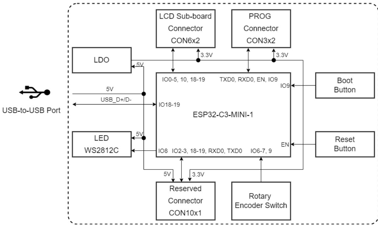
Fig. 12: ESP32-C3-LCD-Ev-Board Block Diagram (Click to Enlarge)
Description of Components The ESP32-C3-LCD-Ev-Board development board consists of a mainboard and a subboard.
Mainboard ESP32-C3-LCD-Ev-Board_MB is the core of the kit, which integrates the ESP32-C3-MINI-1 mod ule and provides ports for connection to the LCD subboard.
The key components of the board are described in a counter-clockwise direction.
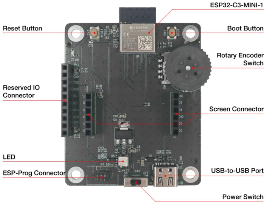
Fig. 13: ESP32-C3-LCD-Ev-Board - Front (Click to Enlarge)
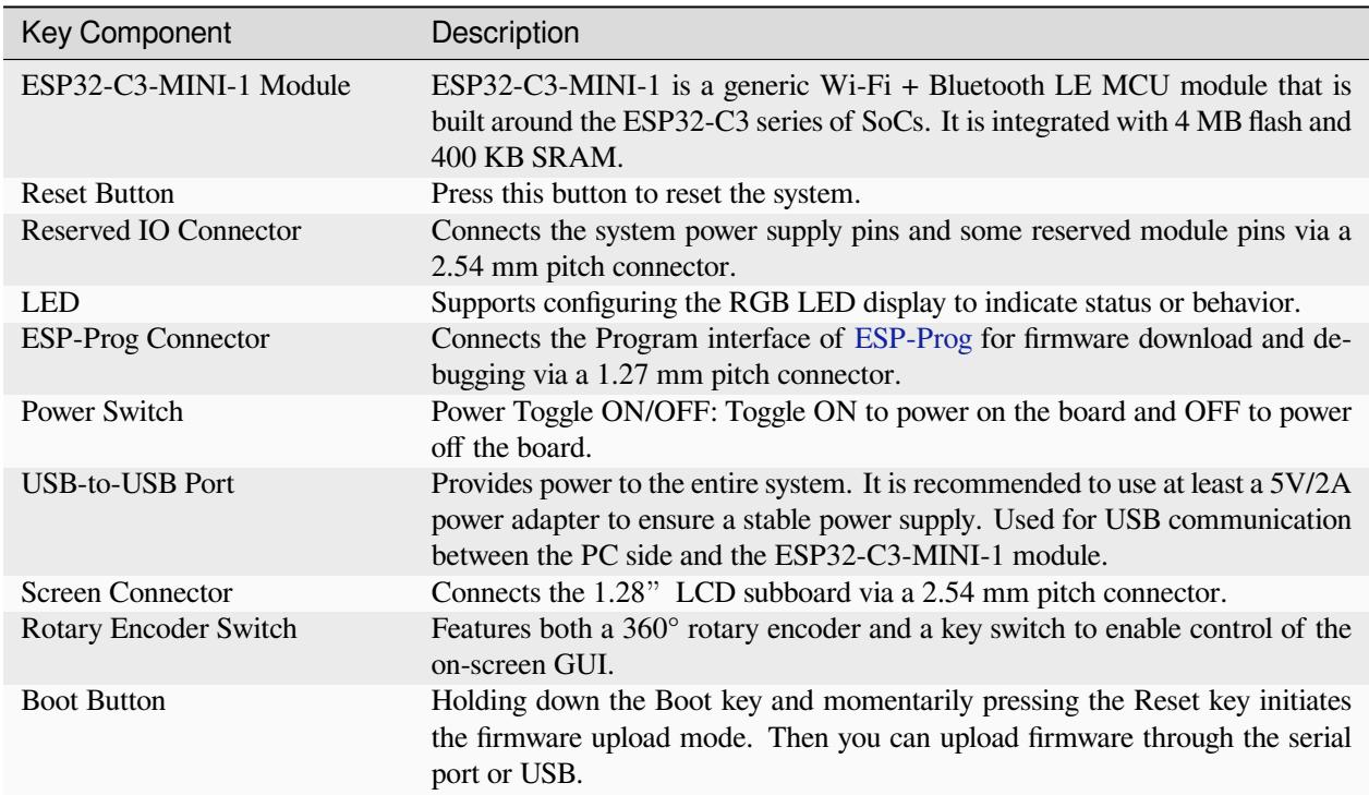
| Key Component | Description |
| ESP32-C3-MINI-1 Module | ESP32-C3-MINI-1 is a generic Wi-Fi + Bluetooth LE MCU module that is built around the ESP32-C3 series of SoCs. It is integrated with 4 MB flash and 400 KB SRAM. |
| Reset Button | Press this button to reset the system. |
| Reserved IO Connector | Connects the system power supply pins and some reserved module pins via a 2.54 mm pitch connector. |
| LED | Supports configuring the RGB LED display to indicate status or behavior. |
| ESP-Prog Connector | Connects the Program interface of ESP-Prog for firmware download and debugging via a 1.27 mm pitch connector. |
| Power Switch | Power Toggle ON/OFF: Toggle ON to power on the board and OFF to power off the board. |
| USB-to-USB Port | Provides power to the entire system. It is recommended to use at least a 5V/2A power adapter to ensure a stable power supply. Used for USB communication between the PC side and the ESP32-C3-MINI-1 module. |
| Screen Connector | Connects the 1.28” LCD subboard via a 2.54 mm pitch connector. |
| Rotary Encoder Switch | Features both a 360° rotary encoder and a key switch to enable control of the on-screen GUI. |
| Boot Button | Holding down the Boot key and momentarily pressing the Reset key initiates the firmware upload mode. Then you can upload firmware through the serial port or USB. |
LCD Subboards The ESP32-C3-LCD-Ev-Board_DB subboard supports a 1.28”LCD screen with SPI interface and 240x240 resolution. The driver chip used for this screen is GC9A01.
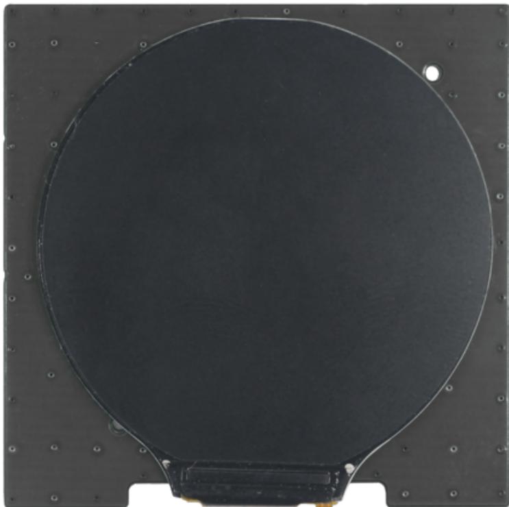
Fig. 14: ESP32-C3-LCD-Ev-Board_DB - Front (Click to Enlarge)
Software Support The ESP32-C3-LCD-Ev-Board development framework is ESP-IDF. ESP-IDF is a FreeRTOSbased SoC development framework with a bunch of components including LCD, ADC, RMT, and SPI.
Application Examples The following application examples are available for ESP32-C3-LCD-Ev-Board:
• Knob Panel Example - Demonstrates a GUI demo for a knob panel with voice playback functionality, providing a reference for developing similar applications using the ESP32-C3-LCDkit.
For more examples and the latest updates, please refer to the examples folder.
To explore the application examples or to develop your own, please follow the steps outlined in the Start Application Development section.
Start Application Development This section provides instructions on how to do hardware and software setup and flash firmware onto the board to develop your own application.
Required Hardware
• 1 x ESP32-C3-LCD-Ev-Board_MB
• 1 x LCD subboard
• 1 x USB 2.0 cable (standard Type-A to Type-C)
• 1 x PC (Windows, Linux, or macOS)
Note: Please make sure to use the appropriate USB cable. Some cables can only be used for charging, not for data transfer or program flashing.
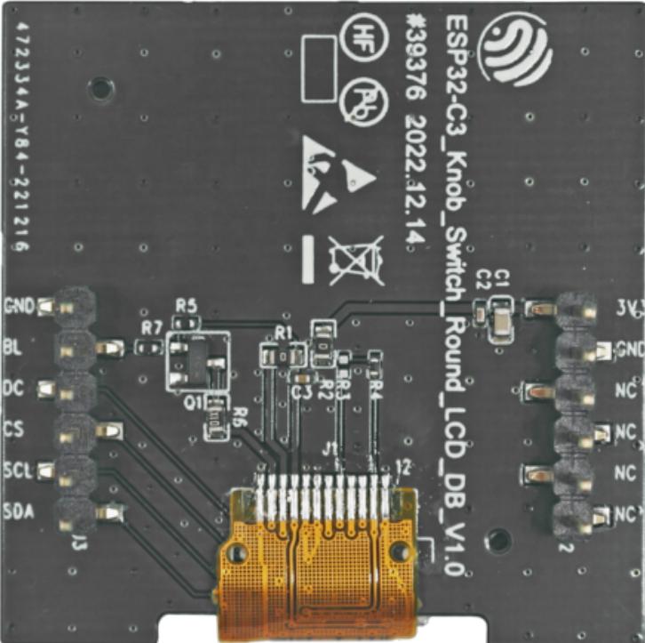
Fig. 15: ESP32-C3-LCD-Ev-Board_DB - Back (Click to Enlarge)
Hardware Setup Prepare the board for loading of the first sample application:
Connect the LCD subboard to the LCD Board Connector.
Plug in the USB cable to connect the PC with the board.
The LCD lights up and you can start to interact with it.
Now the board is ready for software setup.
Software Setup To learn how to quickly set up your development environment, please go to Get Started > Installation.
For more software information on developing applications, please go to Software Support.
Hardware Reference This section provides more detailed information about the board’s hardware.
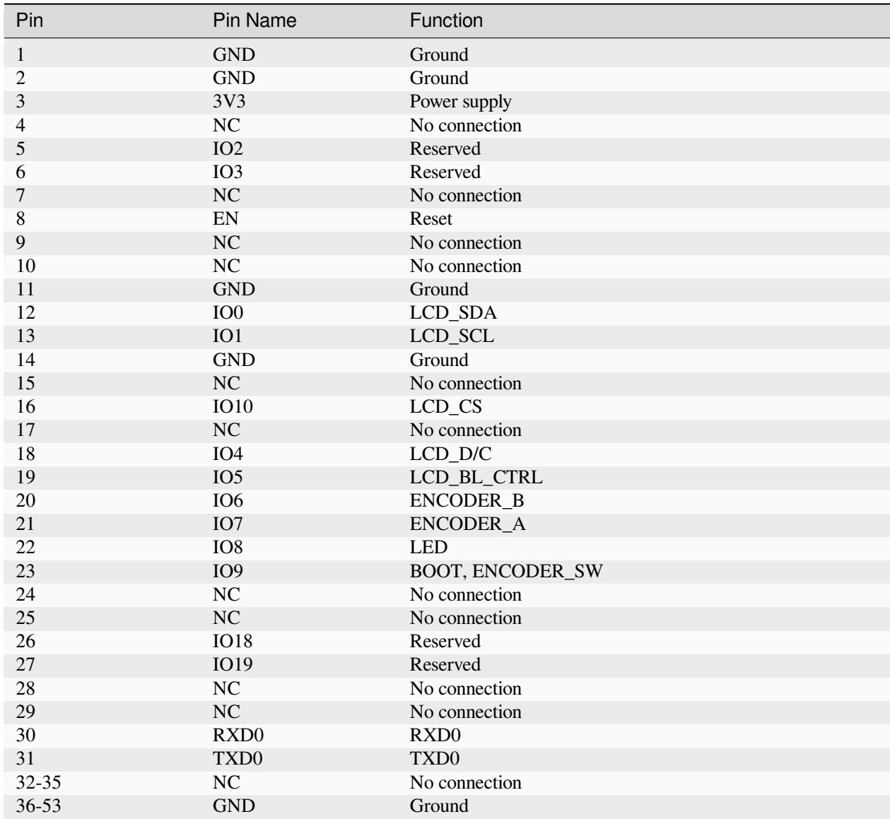
GPIO Allocation The table below provides the allocation of GPIOs exposed on terminals of ESP32-C3-MINI-1 module to control specific components or functions of the board.
Table 2: ESP32-C3-MINI-1 GPIO Allocation
| Pin | Pin Name | Function |
| 1 | GND | Ground |
| 2 | GND | Ground |
| 3 | 3V3 | Power supply |
| 4 | NC | No connection |
| 5 | IO2 | Reserved |
| 6 | IO3 | Reserved |
| 7 | NC | No connection |
| 8 | EN | Reset |
| 9 | NC | No connection |
| 10 | NC | No connection |
| 11 | GND | Ground |
| 12 | IO0 | LCD_SDA |
| 13 | IO1 | LCD_SCL |
| 14 | GND | Ground |
| 15 | NC | No connection |
| 16 | IO10 | LCD_CS |
| 17 | NC | No connection |
| 18 | IO4 | LCD_D/C |
| 19 | IO5 | LCD_BL_CTRL |
| 20 | IO6 | ENCODER_B |
| 21 | IO7 | ENCODER_A |
| 22 | IO8 | LED |
| 23 | IO9 | BOOT, ENCODER_SW |
| 24 | NC | No connection |
| 25 | NC | No connection |
| 26 | IO18 | Reserved |
| 27 | IO19 | Reserved |
| 28 | NC | No connection |
| 29 | NC | No connection |
| 30 | RXD0 | RXD0 |
| 31 | TXD0 | TXD0 |
| 32-35 | NC | No connection |
| 36-53 | GND | Ground |
Power Distribution The development board is powered via the USB-to-USB port:
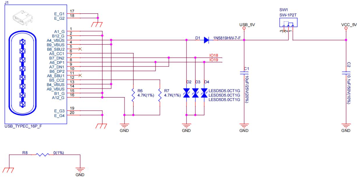
Fig. 16: ESP32-C3-LCD-Ev-Board - USB-to-USB Power Supply
Output system power supply:
3V3 LDO
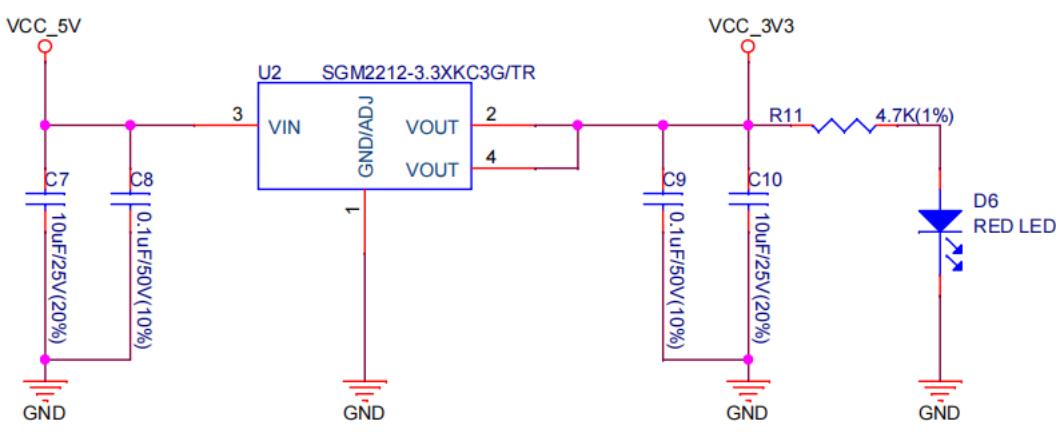
Fig. 17: ESP32-C3-LCD-Ev-Board - System Power Supply
Hardware Setup Options
Automatic Download There are two ways to put the development board into download mode.
• Press the Boot and Reset buttons. Release the Reset button first and then the Boot button.
• Controls the status of the EN and IO9 pins of the ESP development board by ESP-Prog.
Hardware Revision Details No previous revisions.
Sample Request Not available.
Related Documents Please download the following documents from the HTML version of esp-dev-kits Documentation.
• ESP32-C3 Datasheet
• ESP32-C3-MINI-1 Datasheet
• ESP Product Selector
• ESP32-C3-LCD_EV_Board-MB Schematics
• ESP32-C3-LCD_EV_Board-MB PCB Layout
• ESP32-C3-LCD_EV_Board-DB Schematics
• ESP32-C3-LCD_EV_Board-DB PCB Layout
For further design documentation for the board, please contact us at sales@espressif.com.
ESP32-C3-DevKit-RUST-2
ESP32-C3-DevKit-RUST-2 is a development board based on ESP32-C3-MINI-1, a general-purpose module with 4 MB SPI flash. This board integrates complete Wi-Fi and Bluetooth® Low Energy functions.
4.1 ESP32-C3-DevKit-RUST-2
This user guide is intended to help you get started with the ESP32-C3-DevKit-RUST-2 and to provide more detailed technical information for development and integration. The ESP32-C3-DevKit-RUST-2 is a development board based on the ESP32-C3-MINI-1 module, a general-purpose module featuring 4 MB of SPI flash. The board integrates full Wi-Fi and Bluetooth® Low Energy (BLE) connectivity, making it suitable for a wide range of IoT and embedded applications.
In addition to the ESP32-C3, the board integrates onboard sensors and a Li-Ion battery charging circuit, enabling portable and sensor-based applications without requiring external components.
Most I/O pins are routed to pin headers on both sides of the board, allowing easy access to the ESP32-C3 peripherals. Developers can connect external components using jumper wires or mount the ESP32-C3-DevKit-RUST-2 directly on a breadboard for rapid prototyping.
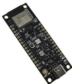
Fig. 1: ESP32-C3-DevKit-RUST-2
The document consists of the following major sections:
• Getting Started: Overview of ESP32-C3-DevKit-RUST-2 and hardware/software setup instructions to get started.
• Hardware Reference: More detailed information about the ESP32-C3-DevKit-RUST-2’s hardware.
• Hardware Revision Details: Revision history, known issues, and links to user guides for previous versions (if any) of ESP32-C3-DevKit-RUST-2.
• Related Documents: Links to related documentation.
4.1.1 Getting Started
This section provides a brief introduction of ESP32-C3-DevKit-RUST-2, instructions on how to do the initial hardware setup and how to flash firmware onto it.
Description of Components
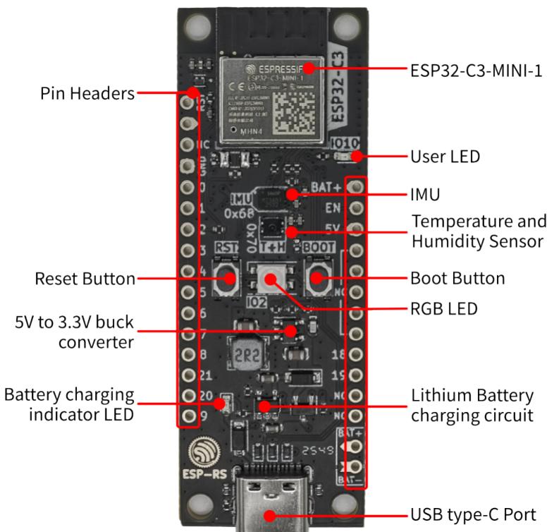
Fig. 2: ESP32-C3-DevKit-RUST-2 (with the ESP32-C3-MINI-1 module) - front
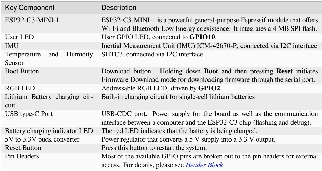
The key components of the board are described starting from the module and continue in the clockwise direction.
| Key Component | Description |
| ESP32-C3-MINI-1 | ESP32-C3-MINI-1 is a powerful general-purpose Espressif module that offers Wi-Fi and Bluetooth Low Energy coexistence. It integrates a 4 MB SPI flash. |
| User LED | User GPIO LED, connected to GPIO10. |
| IMU | Inertial Measurement Unit (IMU) ICM-42670-P, connected via I2C interface |
| Temperature and Humidity Sensor | SHTC3, connected via I2C interface |
| Boot Button | Download button. Holding down Boot and then pressing Reset initiates Firmware Download mode for downloading firmware through the serial port. |
| RGB LED | Addressable RGB LED, driven by GPIO2. |
| Lithium Battery charging circuit | Built-in charging circuit for single-cell lithium batteries |
| USB type-C Port | USB-CDC port. Power supply for the board as well as the communication interface between a computer and the ESP32-C3 chip (flashing and debug). |
| Battery charging indicator LED | The red LED indicates that the battery is being charged. |
| 5V to 3.3V buck converter | Power regulator that converts a 5 V supply into a 3.3 V output. |
| Reset Button | Press this button to restart the system. |
| Pin Headers | Most of the available GPIO pins are broken out to the pin headers for external access. For details, please see Header Block. |
Application Examples
The following application examples are available for ESP32-C3-DevKit-RUST-2:
• ESP-IDF Basic Workshop
• ESP-IDF Advanced Workshop
To explore the application examples or to develop your own, please follow the steps outlined in the Start Application Development section.
Start Application Development
Before powering up your ESP32-C3-DevKit-RUST-2, please make sure that it is in good condition with no obvious signs of damage.
Required Hardware
• ESP32-C3-DevKit-RUST-2
• USB 2.0 cable (USB Type-C)
• Computer running Windows, Linux, or macOS
Note: Be sure to use an appropriate USB cable. Some cables are for charging only and do not provide the needed data lines nor work for programming the boards.
Hardware Setup Connect the board with the computer using the USB type-C Port.
Software Setup Please proceed to ESP-IDF Get Started, which will quickly help you set up the development environment then flash an application example onto your board.
Contents and Packaging
Retail Orders If you order a few samples, each ESP32-C3-DevKit-RUST-2 comes in an individual package in either antistatic bag or any packaging depending on your retailer.
For retail orders, please go to https://www.espressif.com/en/contact-us/get-samples.
4.1.2 Hardware Reference
Block Diagram
The block diagram below shows the components of ESP32-C3-DevKit-RUST-2 and their interconnections.
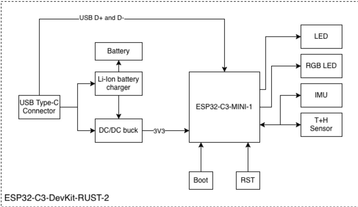
Fig. 3: ESP32-C3-DevKit-RUST-2 (click to enlarge)
Power Supply Options There are three mutually exclusive ways to provide power to the board:
• USB type-C port, default power supply
• 5V and GND pin headers
• BAT and GND pin headers (for single-cell lithium battery)
It is recommended to use the first option: USB type-C port.
Note: The board operates at a 5 V power supply and requires a minimum current of 0.5 A. If your application demands a current exceeding 0.5 A, consider connecting the board via a powered USB hub to ensure stable operation.
Header Block
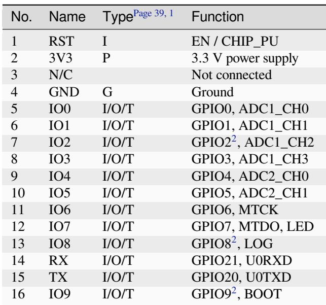
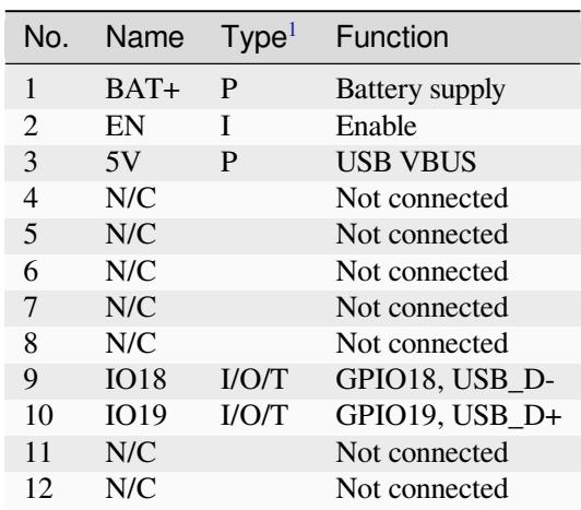
The two tables below provide the Name and Function of the pin headers on both sides of the board (left and right). The pin header names are shown in ESP32-C3-DevKit-RUST-2 (with the ESP32-C3-MINI-1 module) - front. The numbering is the same as in the ESP32-C3-DevKit-RUST-2 Schematic (PDF).
Left Header
| No. | Name | $Type^{Page 39,1}$ | Function |
| 1 | RST | I | EN / CHIP_PU |
| 2 | 3V3 | P | 3.3 V power supply |
| 3 | N/C | Not connected | |
| 4 | GND | G | Ground |
| 5 | IO0 | I/O/T | GPIO0, ADC1_CH0 |
| 6 | IO1 | I/O/T | GPIO1, ADC1_CH1 |
| 7 | IO2 | I/O/T | $GPIO2^2$ , ADC1_CH2 |
| 8 | IO3 | I/O/T | GPIO3, ADC1_CH3 |
| 9 | IO4 | I/O/T | GPIO4, ADC2_CH0 |
| 10 | IO5 | I/O/T | GPIO5, ADC2_CH1 |
| 11 | IO6 | I/O/T | GPIO6, MTCK |
| 12 | IO7 | I/O/T | GPIO7, MTDO, LED |
| 13 | IO8 | I/O/T | $GPIO8^2$ , LOG |
| 14 | RX | I/O/T | GPIO21, U0RXD |
| 15 | TX | I/O/T | GPIO20, U0TXD |
| 16 | IO9 | I/O/T | $GPIO9^2$ , BOOT |
Right Header
| No. | Name | Type $^{1}$ | Function |
| 1 | BAT+ | P | Battery supply |
| 2 | EN | I | Enable |
| 3 | 5V | P | USB VBUS |
| 4 | N/C | Not connected | |
| 5 | N/C | Not connected | |
| 6 | N/C | Not connected | |
| 7 | N/C | Not connected | |
| 8 | N/C | Not connected | |
| 9 | IO18 | I/O/T | GPIO18, USB_D- |
| 10 | IO19 | I/O/T | GPIO19, USB_D+ |
| 11 | N/C | Not connected | |
| 12 | N/C | Not connected |
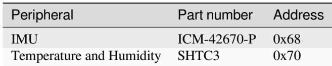
I2C Peripherals
| Peripheral | Part number | Address |
| IMU | ICM-42670-P | 0x68 |
| Temperature and Humidity | SHTC3 | 0x70 |
Sensors
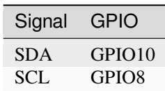
I2C Signal Mapping
| Signal | GPIO |
| SDA | GPIO10 |
| SCL | GPIO8 |
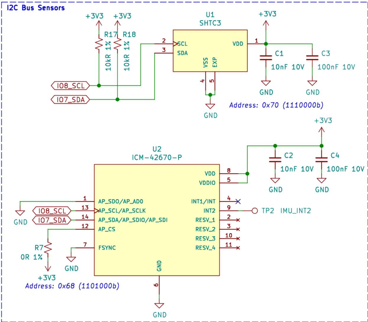
Fig. 4: Sensors on I2C bus (click to enlarge)
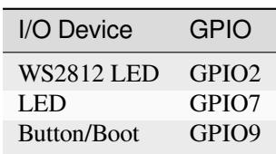
Peripherals Connected to GPIOs
| I/O Device | GPIO |
| WS2812 LED | GPIO2 |
| LED | GPIO7 |
| Button/Boot | GPIO9 |
Buttons
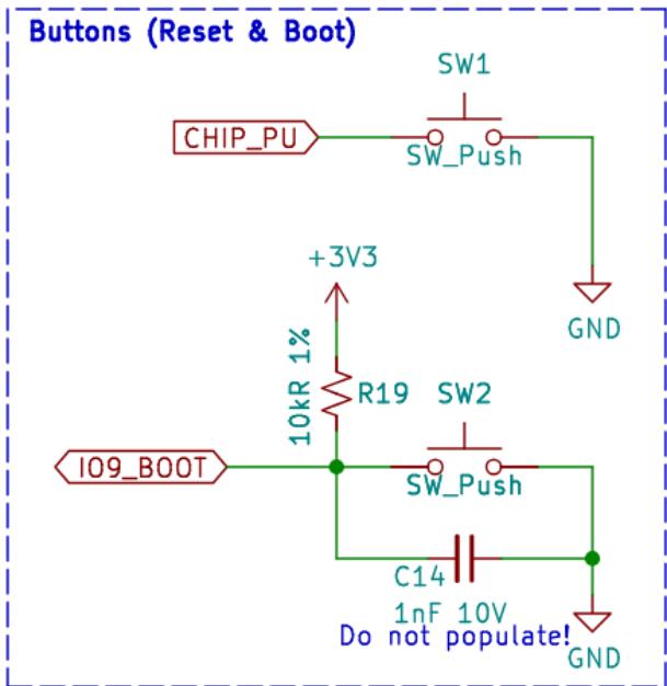
Fig. 5: Buttons Circuit (click to enlarge)
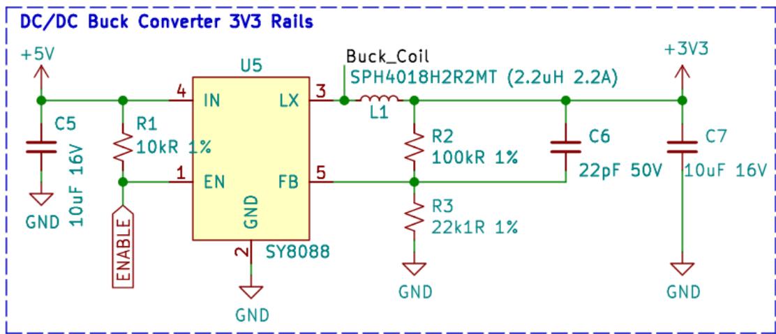
Fig. 6: Power Supply Circuit (click to enlarge)
Power Supply
Power Supply from USB
Lithium Battery Charging
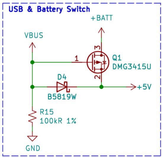
Fig. 7: Power Switch Circuit (click to enlarge)
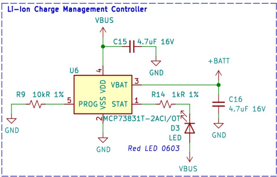
Fig. 8: Lithium Battery charging circuit (click to enlarge)
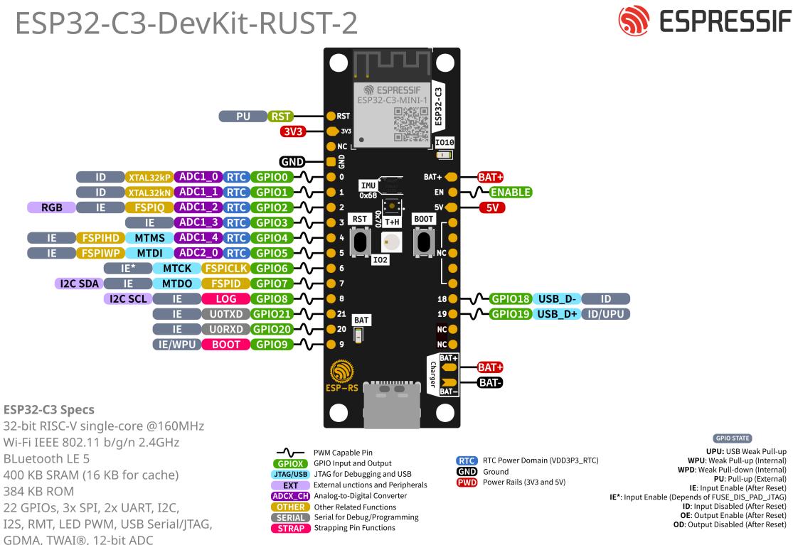
Fig. 9: ESP32-C3-DevKit-RUST-2 Pin Layout (with the ESP32-C3-MINI-1 module, click to enlarge)
Pin Layout
4.1.3 Hardware Revision Details
This is a new version with minor changes from the previous ESP32-C3-DevKit-RUST-1 board. The list of changes are as follows:
• Changed the GPIO for the user LED from GPIO7 to GPIO10.
• Changed the pin header hole diameter from 0.8 mm to 1.0 mm.
• Fixed issues on the silkscreen layer.
• Changes on the traces on the I2C bus for better signal integrity.
4.1.4 Related Documents
• ESP32-C3 Datasheet (PDF)
• ESP32-C3-MINI-1 & ESP32-C3-MINI-1U Datasheet (PDF)
• ESP32-C3-DevKit-RUST-2 Schematic (PDF)
• ESP32-C3-DevKit-RUST-2 PCB Layout (PDF)
• ESP-IDF Programming Guide
• ESP32-C3-DevKit-RUST-2 training
For further design documentation for the board, please contact us at sales@espressif.com.
ESP32-C3 Development Boards
ESP32-C3-DevKitC-02
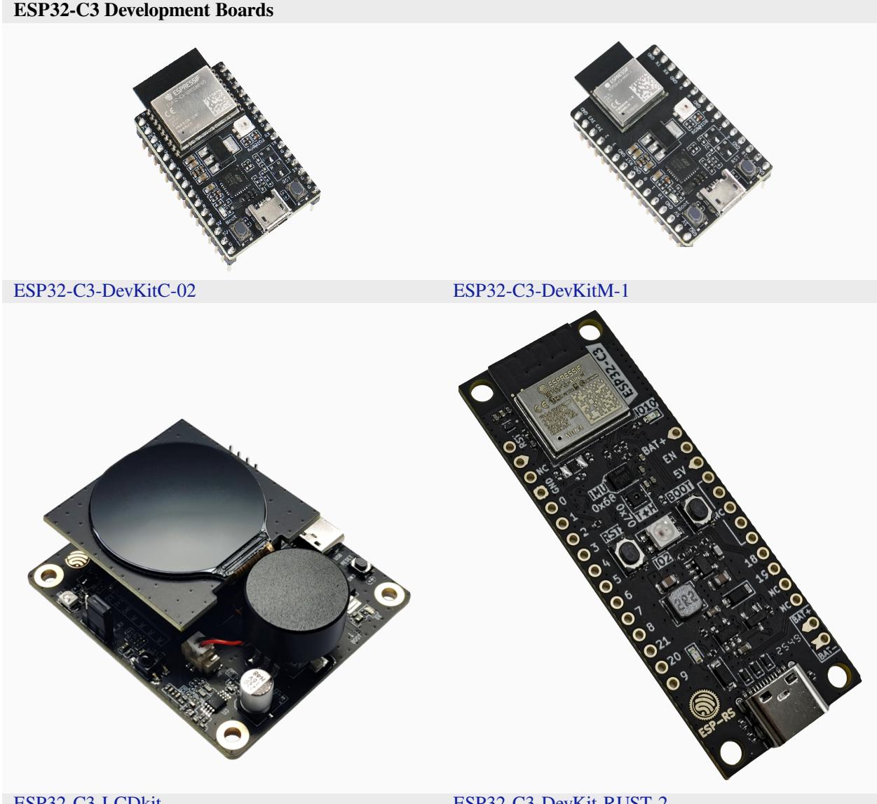
ESP32-C3-LCDkit
ESP32-C3-DevKitM-1
ESP32-C3-DevKit-RUST-2
Related Documentation and Resources
5.1 Related Documentation
• ESP32-C3 Datasheet –Specifications of the ESP32-C3 hardware.
• ESP32-C3 Technical Reference Manual –Detailed information on how to use the ESP32-C3 memory and peripherals.
• ESP32-C3 Hardware Design Guidelines –Guidelines on how to integrate the ESP32-C3 into your hardware product.
• ESP32-C3 Product/Process Change Notifications (PCN) https://espressif.com/en/support/documents/pcns?keys=ESP32-C3
• ESP32-C3 Advisories –Information on security, bugs, compatibility, component reliability. https://espressif.com/en/support/documents/advisories?keys=ESP32-C3
• Certificates
https://espressif.com/en/support/documents/certificates
• Documentation Updates and Update Notification Subscription https://espressif.com/en/support/download/documents
5.2 Developer Zone
• ESP-IDF Programming Guide for ESP32-C3 –Extensive documentation for the ESP-IDF development framework.
• ESP-IoT-Solution Programming Guide - Extensive documentation for the ESP-IoT-Solution development framework.
• ESP-FAQ - A summary document of frequently asked questions released by Espressif.
• ESP-IDF and other development frameworks on GitHub.
• ESP32 BBS Forum –Engineer-to-Engineer (E2E) Community for Espressif products where you can post questions, share knowledge, explore ideas, and help solve problems with fellow engineers. https://esp32.com
• The ESP Journal –Best Practices, Articles, and Notes from Espressif folks. https://blog.espressif.com/
• See the tabs SDKs and Demos, Apps, Tools, AT Firmware. https://espressif.com/en/support/download/sdks-demos
5.3 Products
• ESP32-C3 Series SoCs –Browse through all ESP32-C3 SoCs. https://espressif.com/en/products/socs?id=ESP32-C3
• ESP32-C3 Series Modules –Browse through all ESP32-C3-based modules. https://espressif.com/en/products/modules?id=ESP32-C3
• ESP32-C3 Series DevKits –Browse through all ESP32-C3-based devkits. https://espressif.com/en/products/devkits?id=ESP32-C3
• ESP Product Selector –Find an Espressif hardware product suitable for your needs by comparing or applying filters.
https://products.espressif.com/#/product-selector
5.4 Contact Us
• See the tabs Sales Questions, Technical Enquiries, Circuit Schematic & PCB Design Review, Get Samples (Online stores), Become Our Supplier, Comments & Suggestions. https://espressif.com/en/contact-us/sales-questions
Disclaimer and Copyright Notice
Information in this document, including URL references, is subject to change without notice.
All third party’s information in this document is provided as is with no warranties to its authenticity and accuracy.
No warranty is provided to this document for its merchantability, non-infringement, fitness for any particular purpose, nor does any warranty otherwise arising out of any proposal, specification or sample.
All liability, including liability for infringement of any proprietary rights, relating to use of information in this document is disclaimed. No licenses express or implied, by estoppel or otherwise, to any intellectual property rights are granted herein.
The Wi-Fi Alliance Member logo is a trademark of the Wi-Fi Alliance. The Bluetooth logo is a registered trademark of Bluetooth SIG.
All trade names, trademarks and registered trademarks mentioned in this document are property of their respective owners, and are hereby acknowledged.
Figures and diagrams from the PDF
Preview the extracted datasheet assets and open any image in a separate tab for closer inspection.
Use this datasheet from any agent
Send the page, markdown, chunks, or search endpoint to ChatGPT, Claude, embedr-app, or your own tooling.