
LTC1502-3.3
Micropower regulated 3.3 V quadrupler charge pump DC/DC converter for single-cell input supplies.
FEATURES
■ Input Voltage Range: 0.9V to 1.8V
■ 0.9V Guaranteed Start-Up Voltage
■ Regulated Output Voltage: $3 . 3 V \pm 4 %$
■ Output Current: 10mA $( V _ { | \mathsf { N } } \geq 1 V )$
■ No Inductors
■ Shutdown Disconnects Load from ${ \tt V } _ { \sf I N }$
■ Low Operating Current: $4 0 \mu \ A$
■ Low Shutdown Current: $5 \mu \ A$
■ Short-Circuit and Overtemperature Protected
■ Application Circuit Fits $\sin < 0 . 1 2 5 \mathrm { i n } ^ { 2 }$ PCB Area
■ Available in 8-Pin MSOP and SO Packages
APPLICATIO SU
■ Pagers
■ Battery Backup Supplies
■ Portable Electronic Equipment
■ Handheld Medical Instruments
■ Glucose Meters
TYPICAL APPLICATIOU
Single Cell to 3.3V DC/DC Converter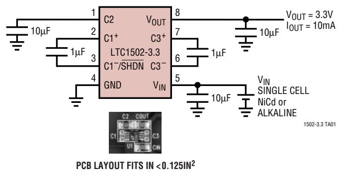
Single Cell to 3.3V Regulated Charge Pump DC/DC Converter
DESCRIPTIOU
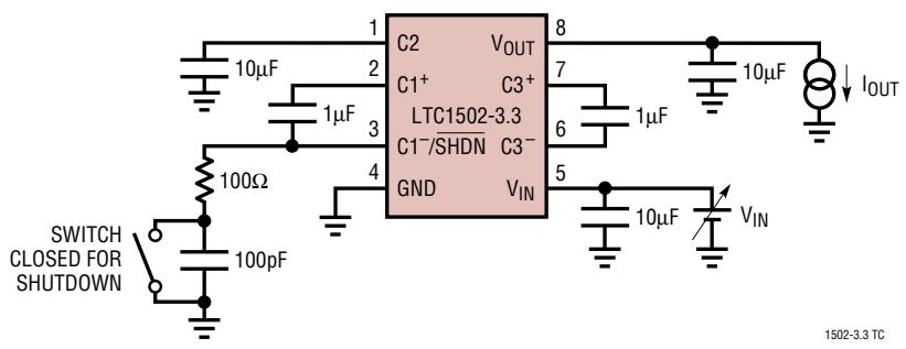
The LTC®1502-3.3 is a quadrupler charge pump DC/DC converter that produces a regulated 3.3V output from a single alkaline cell input. It requires only five small external capacitors—no inductors are required. Low supply current (40µA typical, 5µA in shutdown) and minimal external components make the LTC1502-3.3 ideal for space and power conscious single-cell applications. The total printed circuit board area of the circuit shown below is less than $0 . 1 2 5 \mathrm { i n } ^ { 2 }$
Forcing the C1–/SHDN pin low through an external resistive pull-down puts the part into shutdown mode. During shutdown, the internal oscillator is stopped and the load is disconnected from $\mathsf { V } _ { \mathsf { I N } } .$ . An internal pull-up current on the C1–/SHDN pin forces the part back into normal operation once the pull-down resistance is removed.
The LTC1502-3.3 is short-circuit protected and survives an indefinite $\mathsf { V } _ { 0 \mathsf { U } \mathsf { T } }$ short to ground. The LTC1502-3.3 is available in 8-pin MSOP and SO packages.
ABSOLUTE MAXIMUM RATINGS W WW U (Note 1)
$\mathsf { V } _ { \mathsf { I N } }$ to GND . –0.3V to 2V $\mathsf { V } _ { 0 \mathsf { U } \mathsf { T } }$ to GND .. –0.3V to 5V All Other Pins to GND ... –0.3V to 5V $\mathsf { V } _ { 0 \mathsf { U } \mathsf { T } }$ Short-Circuit Duration .. Indefinite Storage Temperature Range . $- 6 5 ^ { \circ } \complement$ to $1 5 0 %$
Operating Temperature Range Commercial . $0 %$ to $7 0 %$ Extended Commercial (Note 4) .... $- 4 0 %$ to $8 5 \mathrm { ^ \circ C }$ Industrial . $- 4 0 %$ to $8 5 \mathrm { ^ \circ C }$ Lead Temperature (Soldering, 10 sec)... 300°C
PACKAGE/ORDER INFORMATION U W U
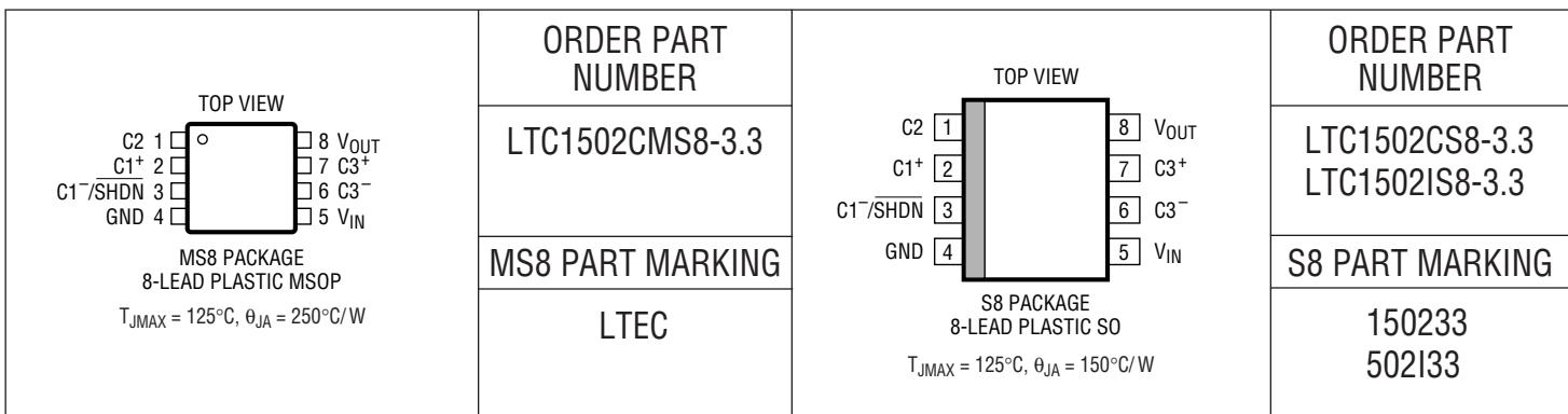
Consult factory for Military grade parts.
ELECTRICAL CHARACTERISTICS
The ● denotes the specifications which apply over the full operating temperature range, otherwise specifications are at ${ \bar { \mathbf { I } } } _ { \mathsf { A } } = 2 5 ^ { \circ } { \bar { \mathbf { C } } } ,$ VIN = 0.9V to 1.8V, C1 = C3 = 1µF, $\complement _ { \mid \mathsf { N } } = \dot { \mathsf { C } } \dot { 2 } = \mathsf { C } _ { 0 \mathsf { U } \mathsf { T } } = 1 \mathbf { 0 } \mu \mathsf { F }$ unless otherwise specified.
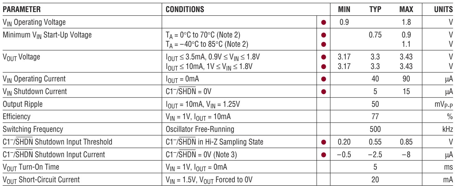
| PARAMETER | CONDITIONS | MIN | TYP | MAX | UNITS | |
| $V_{IN}$ Operating Voltage | ● | 0.9 | 1.8 | V | ||
| Minimum $V_{IN}$ Start-Up Voltage | $T_A = 0°C$ to $70°C$ (Note 2) $T_A = -40°C$ to $85°C$ (Note 2) | ● | 0.75 | 0.9 | V | |
| ● | 1.1 | V | ||||
| $V_{OUT}$ Voltage | $I_{OUT} \leq 3.5mA, 0.9V \leq V_{IN} \leq 1.8V$ $I_{OUT} \leq 10mA, 1V \leq V_{IN} \leq 1.8V$ | ● | 3.17 | 3.3 | 3.43 | V |
| ● | 3.17 | 3.3 | 3.43 | V | ||
| $V_{IN}$ Operating Current | $I_{OUT} = 0mA$ | ● | 40 | 90 | μA | |
| $V_{IN}$ Shutdown Current | $C1^{-}/\overline{SHDN} = 0V$ | ● | 5 | 15 | μA | |
| Output Ripple | $I_{OUT} = 10mA, V_{IN} = 1.25V$ | 50 | $mV_{P-P}$ | |||
| Efficiency | $V_{IN} = 1V, I_{OUT} = 10mA$ | 77 | % | |||
| Switching Frequency | Oscillator Free-Running | 500 | kHz | |||
| $C1^{-}/\overline{SHDN}$ Shutdown Input Threshold | $C1^{-}/\overline{SHDN}$ in Hi-Z Sampling State | ● | 0.20 | 0.55 | 0.85 | V |
| $C1^{-}/\overline{SHDN}$ Shutdown Input Current | $C1^{-}/\overline{SHDN} = 0V$ (Note 3) | ● | -0.5 | -2.5 | -8 | μA |
| $V_{OUT}$ Turn-On Time | $V_{IN} = 1V, I_{OUT} = 0mA$ | 5 | ms | |||
| $V_{OUT}$ Short-Circuit Current | $V_{IN} = 1.5V, V_{OUT}$ Forced to 0V | 20 | mA | |||
Note 1: Absolute Maximum Ratings are those values beyond which the life of the device may be impaired.
Note 4: Commercial grade specifications are guaranteed over the 0°C to 70°C operating temperature range. In addition, commercial grade specifications are assured over the –40°C to 85°C operating temperature range by design, characterization and correlation with statistical process controls. Industrial grade specifications are guaranteed and tested over the –40°C to 85°C operating temperature range.
Note 2: Start-up testing is done with a 100kΩ equivalent load on $\mathsf { V } _ { 0 \mathsf { U T } } .$ Note 3: Currents flowing into the device are positive polarity. Currents flowing out of the device are negative polarity.
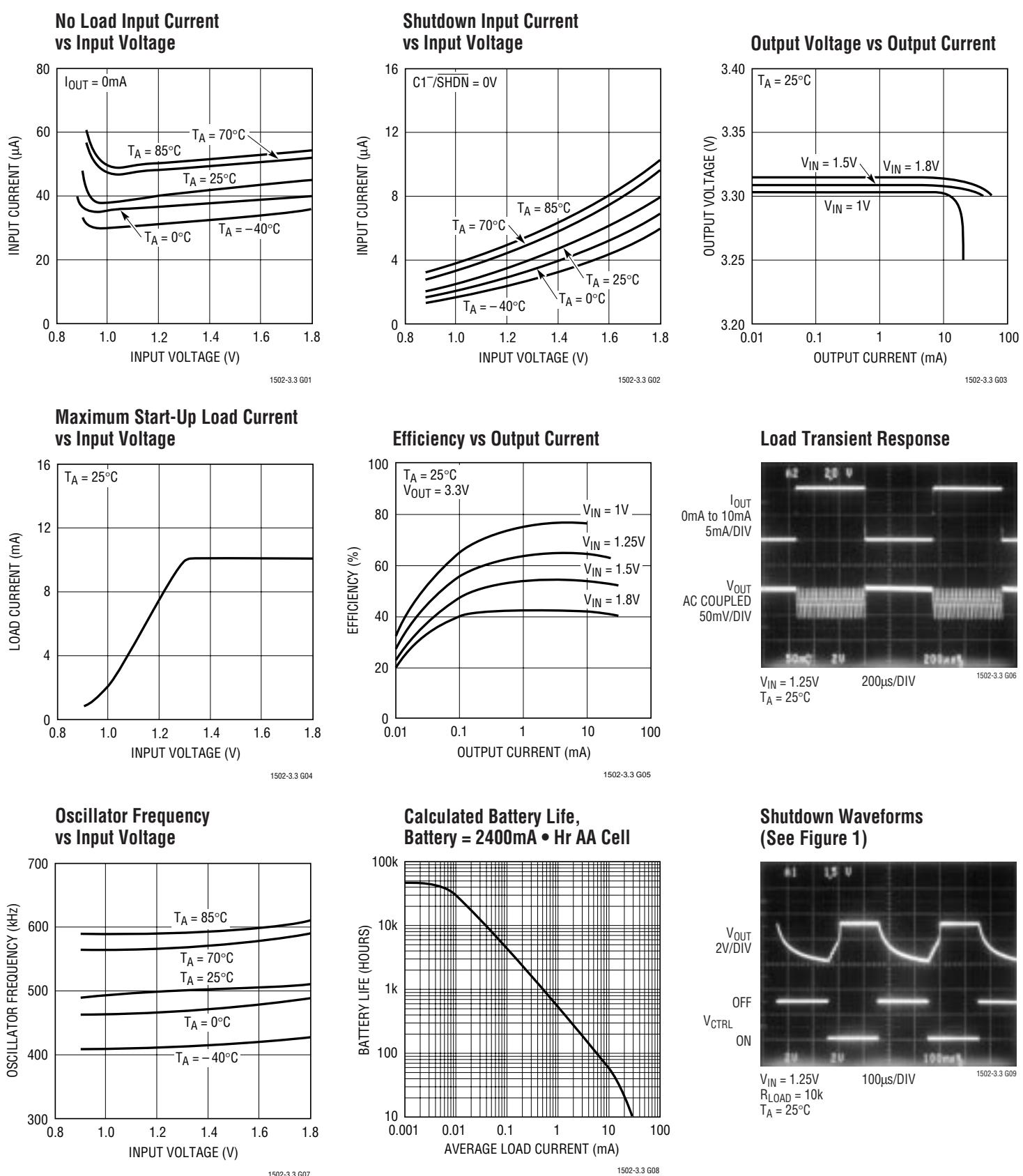
TYPICAL PERFOR A CE CHARACTERISTICSUW
PIN FUNCTIONSUUU
C2 (Pin 1): Charge Pump 1 (CP1) Output. This pin also serves as the input supply for charge pump 2 (CP2). To ensure proper start-up, the C2 pin must not be externally loaded. Bypass the C2 pin with $\mathtt { a } \ge 1 0 \mu \mathsf { F }$ low ESR capacitor to ground.
C1+ (Pin 2): Charge Pump 1 Flying Capacitor Positive Terminal.
C1–/SHDN (Pin 3): Charge Pump 1 Flying Capacitor Negative Terminal and Shutdown Input. Pulling this pin to ground through a ≈ 100Ω resistor will put the part into shutdown mode. With a high resistance pull-down FET, the series resistor may be eliminated. The external pulldown device must be high impedance for normal operation (see Applications Information). Peak voltage present on this pin is approximately equal to $\mathsf { V } _ { \mathsf { I N } }$
GND (Pin 4): Ground. Connect to a ground plane for best performance.
VIN (Pin 5): Input Supply Voltage. Bypass $\mathsf { V } _ { \mathsf { I N } }$ with a ≥10µF low ESR capacitor to ground.
C3– (Pin 6): Charge Pump 2 (CP2) Flying Capacitor Negative Terminal.
C3+ (Pin 7): Charge Pump 2 Flying Capacitor Positive Terminal.
VOUT (Pin 8): 3.3V Regulated Output Voltage. VOUT is disconnected from $\mathsf { V } _ { \mathsf { I N } }$ during shutdown. Bypass VOUT with $\mathsf { a } \geq 1 0 \mu \mathsf { F }$ low ESR capacitor to ground.
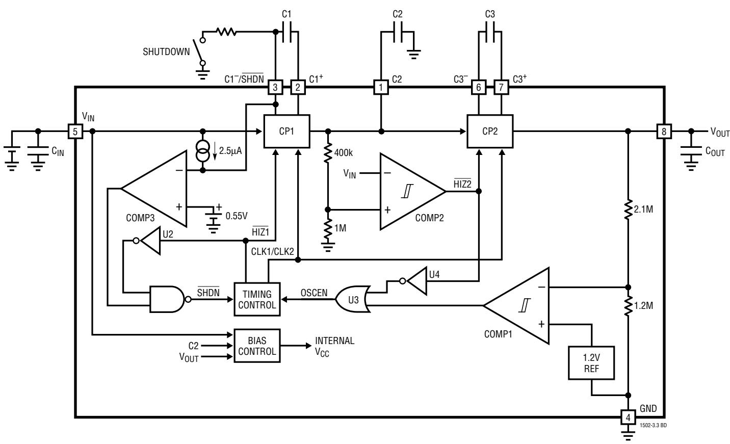
BLOCK DIAGRAMW
TEST CIRCUIT
APPLICATIONS INFORMATION U WU U
Regulator Operation
The LTC1502-3.3 uses a quadrupler charge pump DC/DC converter to produce a boosted output voltage. The quadrupler charge pump consists of two voltage doubler charge pumps (CP1 and CP2 on the Block Diagram) cascaded in series. CP1 doubles the input voltage $\mathsf { V } _ { \mathsf { I N } }$ and the CP1 output voltage is stored on external capacitor C2. The C2 pin also serves as the input for doubler CP2 whose output is stored on the output capacitor $\complement _ { 0 \cup \intercal }$ . Each doubler is controlled by a two-phase clock which is generated in the Timing Control circuit. On phase one of the clock, the flying capacitors C1 and C3 are charged to their respective input voltages. On phase two each charged flying capacitor is stacked on top of the input voltage and discharged through an internal switch onto its respective output. This sequence of charging and discharging the CP1 and CP2 flying capacitors continues at the free running oscillator frequency (500kHz typ) until the output is in regulation.
Regulation is achieved by comparing the divided down output voltage to a fixed voltage reference. The charge pump clocks are disabled when the output voltage is above the desired regulation point set by COMP1. When the output has dropped below the lower trip point of COMP1, the charge pump clocks are turned back on until $\mathsf { V } _ { 0 \mathsf { U } \mathsf { T } }$ is boosted back into regulation.
Enhanced Start-Up
Enhanced start-up capability is provided by the COMP2 circuitry. COMP2 compares the divided down C2 voltage to the input voltage $\mathsf { V } _ { | \mathsf { N } } .$ . The COMP2 output disables the output charge pump CP2 whenever the divided C2 voltage is lower than $\mathsf { V } _ { \mathsf { I N } }$ . The CP2 output is thereby forced into a high impedance state until the voltage on C2 has been raised above $\mathsf { V } _ { \mathsf { I N } }$ (the C2 pin should not be loaded for proper start-up). This allows a higher internal gate drive voltage to be generated (from the C2 pin) before the output $( \mathsf { V } _ { 0 \mathsf { U T } } )$ is connected to a load. Hysteresis in COMP2 forces CP2 to be turned ON and OFF while $\complement _ { 0 \cup \intercal }$ is charging up to prevent a lockup condition if C2 droops too low during start-up. By the time the output nears the regulation point, the C2 voltage is well above the lower trip point of COMP2 and CP2 will remain enabled. This method of disabling the output charge pump while an internal boosted gate drive supply is developed allows the part to start up at low voltages with a larger output current load than would otherwise be possible.
Shutdown
Shutdown is implemented using an external pull-down device on the C1–/SHDN pin. The recommended external pull-down device is an open-drain FET with resistive current limiting (see Figure 1). The pull-down device must sink up to $3 0 0 \mu \ A$ and pull down below 0.2V to ensure proper shutdown operation, however, the actual series resistance is not critical. The pull-down device must also go into a Hi-Z state for the LTC1502-3.3 to become active.
The timing control circuitry forces the CP1 switches into a high impedance state every 16 clock cycles. The Hi-Z duration is equal to one clock cycle. At the end of the Hi-Z time interval, the voltage on the C1–/SHDN pin is sampled. If the C1–/SHDN pin has been pulled to a logic low state, the part will go into shutdown mode. When the pull-down device is disabled, an internal pull-up current
APPLICATIONS INFORMATIONU WU U
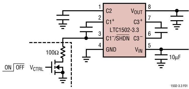
Figure 1. Pull-Down Circuitry for Shutdown
will force a logic high on the C1–/SHDN pin and put the part back into active mode. If no external pull-down is present during the Hi-Z interval, the internal pull-up current will maintain a logic high on the C1–/SHDN pin thereby keeping the part in active mode.
The shutdown feature can be used to prevent charge pump switching during noise sensitive intervals. Since the charge pump oscillator is disabled during shutdown, output switching noise can be eliminated while the external pull-down is active. The LTC1502-3.3 takes between $2 0 \mu \ s$ and $5 0 \mu \ s$ to switch from shutdown to active mode once the pull-down device has been turned off (assuming a 100pF external capacitance to GND on the C1–/SHDN pin). A 100k pull-up resistor from $\mathsf { V } _ { \mathsf { I N } }$ to C1–/SHDN will speed up this transition by a factor of five at the expense of $1 0 \mu \mathsf { A }$ or so of additional shutdown current. To maintain regulation, a sufficiently large output capacitor must be used to prevent excessive $\mathsf { V } _ { 0 \mathsf { U } \mathsf { T } }$ droop while the charge pump is in shutdown. Also, there must be adequate time for the charge pump to recharge the output capacitor while the part is active. In other words, the average load current must be low enough for the LTC1502-3.3 to maintain a 3.3V output while the part is active.
Capacitor Selection
For best performance, it is recommended that low ESR capacitors be used for $\complement _ { | N } ,$ C2 and $\complement _ { 0 \cup \intercal }$ to reduce noise and ripple. The $\complement _ { | \ N : }$ C2 and $\complement _ { 0 \cup \intercal }$ capacitors should be either ceramic or tantalum and should be $1 0 \mu \bar { \sf F }$ or greater. If the input source impedance is very low (< 0.5Ω), $\complement _ { \mathsf { I N } }$ may not be needed. Ceramic capacitors are recommended for the flying capacitors C1 and C3 with values of $0 . 4 7 \mu \mathsf { F }$ to $2 . 2 \mu \ F$ . Smaller values may be used in low output current applications $( \Theta . 9 . , \vert _ { 0 \mathsf { U } \mathsf { T } } < 1 \mathsf { m A } )$
Output Ripple
Normal LTC1502-3.3 operation produces voltage ripple on the $\mathsf { V } _ { 0 \mathsf { U } \mathsf { T } }$ pin. Output voltage ripple is required for regulation. Low frequency ripple exists due to the hysteresis in the sense comparator and propagation delays in the charge pump enable/disable circuits. High frequency ripple is also present mainly from the ESR (equivalent series resistance) in the output capacitor. Typical output ripple $( V _ { | \mathsf { N } } = 1 . 2 5 V )$ under maximum load is 50mV peak-to-peak with a low ESR $1 0 \mu \bar { \sf F }$ output capacitor.
The magnitude of the ripple voltage depends on several factors. High input voltages increase the output ripple since more charge is delivered to $\complement _ { 0 \cup \intercal }$ per charging cycle. Large output current load and/or a small output capacitor $( < 1 0 \mu \bar { \sf F } )$ results in higher ripple due to higher output voltage dV/dt. High ESR capacitors $( \mathsf { E S R } > 0 . 5 \Omega )$ on the output pin cause high frequency voltage spikes on $\mathsf { V } _ { 0 \mathsf { U } \mathsf { T } }$ with every clock cycle.
There are several ways to reduce the output voltage ripple. A larger $\complement _ { 0 \cup \intercal }$ capacitor $( 2 2 \mu \ F$ or greater) will reduce both the low and high frequency ripple due to the lower COUT charging and discharging dV/dt and the lower ESR typically found with higher value (larger case size) capacitors. A low ESR ceramic output capacitor will minimize the high frequency ripple, but will not reduce the low frequency ripple unless a high capacitance value is chosen. A reasonable compromise is to use a $1 0 \mu \bar { \sf F }$ to $2 2 \mu \ F$ tantalum capacitor in parallel with a $1 \mu \mathsf { F }$ to 3.3µF ceramic capacitor on $\mathsf { V } _ { 0 \mathsf { U } \mathsf { T } }$ to reduce both the low and high frequency ripple. An RC filter may also be used to reduce high frequency voltage spikes (see Figure 2).
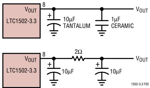
Figure 2. Output Ripple Reduction Techniques
APPLICATIONS INFORMATIONU WU U
Short-Circuit Protection
When the output is shorted to ground, the LTC1502-3.3 will continuously charge the C2 capacitor up to approximately 1.4 times $\mathsf { V } _ { \mathsf { I N } } ,$ and then discharge C2 into the shorted output. Since the discharging of C2 into $\mathsf { V } _ { 0 \mathsf { U } \mathsf { T } }$ will bring the C2 voltage below the COMP2 start-up comparator trip voltage, the output charge pump will be forced Hi-Z while C2 charges up again. Hence, the internal charge pump gate drive voltage is limited to $( 1 . 4 ) ( \mathsf { V } _ { | \mathsf { N } ( \mathsf { M A X } ) } )$ on the C2 pin, and no continuous current is supplied to $\mathsf { V } _ { 0 \mathsf { U } \mathsf { T } }$ . The resulting output short-circuit current is limited to under 20mA (typ) thereby allowing the LTC1502-3.3 to endure an indefinite output short circuit without damage. When the short is removed, the part will start up, and operate normally.
PACKAGE DESCRIPTIONU Dimensions in inches (millimeters) unless otherwise noted.
MS8 Package 8-Lead Plastic MSOP (LTC DWG # 05-08-1660)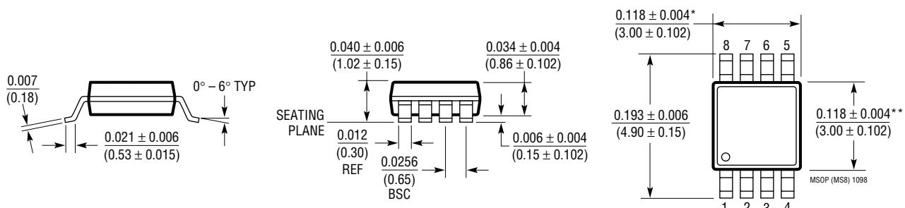
DIMENSION DOES NOT INCLUDE MOLD FLASH, PROTRUSIONS OR GATE BURRS. MOLD FLASH, PROTRUSIONS OR GATE BURRS SHALL NOT EXCEED 0.006" (0.152mm) PER SIDE
** DIMENSION DOES NOT INCLUDE INTERLEAD FLASH OR PROTRUSIONS. INTERLEAD FLASH OR PROTRUSIONS SHALL NOT EXCEED 0.006" (0.152mm) PER SIDE
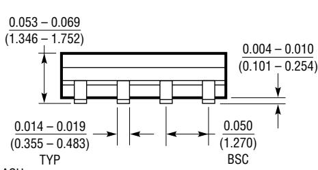
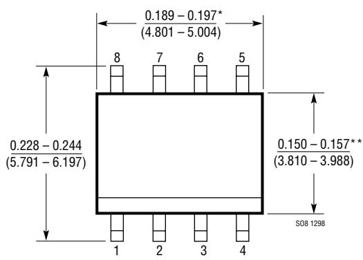
S8 Package 8-Lead Plastic Small Outline (Narrow 0.150) (LTC DWG # 05-08-1610)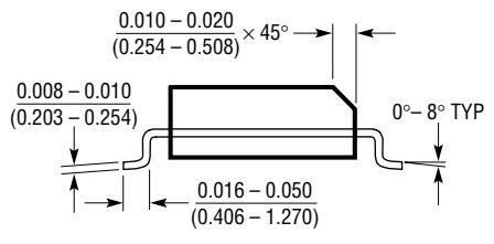
DIMENSION DOES NOT INCLUDE MOLD FLASH. MOLD FLASH*
SHALL NOT EXCEED 0.006" (0.152mm) PER SIDE
DIMENSION DOES NOT INCLUDE INTERLEAD FLASH. INTERLEAD** FLASH SHALL NOT EXCEED 0.010" (0.254mm) PER SIDE
TYPICAL APPLICATIONSU
Single Cell to 3.3V DC/DC Converter with Shutdown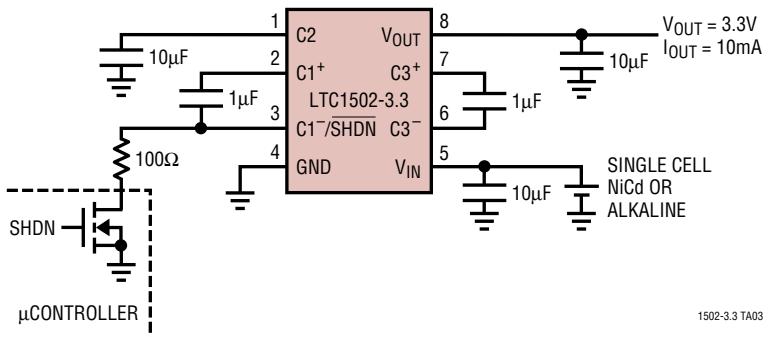
Single Cell Battery Backup Supply with Autoswitchover and No Reverse Current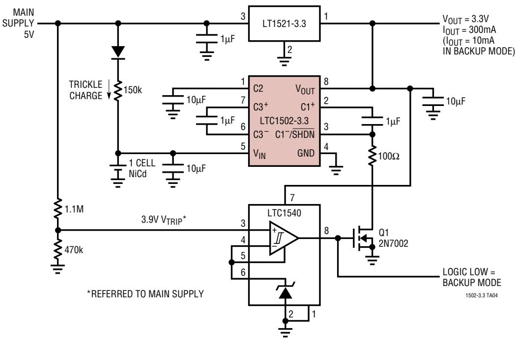
RELATED PARTS
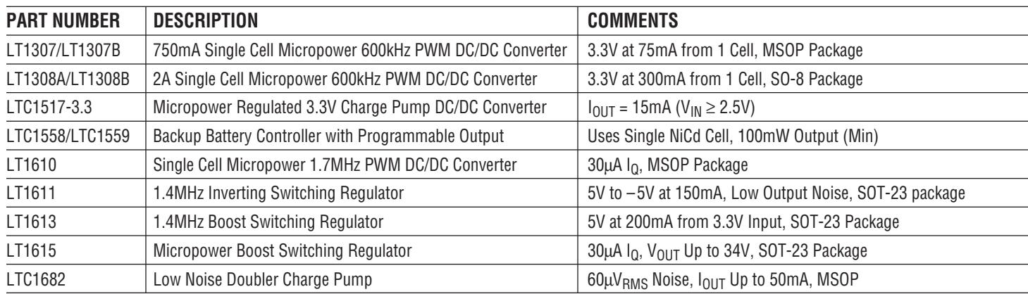
| PART NUMBER | DESCRIPTION | COMMENTS |
| LT1307/LT1307B | 750mA Single Cell Micropower 600kHz PWM DC/DC Converter | 3.3V at 75mA from 1 Cell, MSOP Package |
| LT1308A/LT1308B | 2A Single Cell Micropower 600kHz PWM DC/DC Converter | 3.3V at 300mA from 1 Cell, SO-8 Package |
| LTC1517-3.3 | Micropower Regulated 3.3V Charge Pump DC/DC Converter | $I_{OUT} = 15mA (V_{IN} \geq 2.5V)$ |
| LTC1558/LTC1559 | Backup Battery Controller with Programmable Output | Uses Single NiCd Cell, 100mW Output (Min) |
| LT1610 | Single Cell Micropower 1.7MHz PWM DC/DC Converter | 30μA $I_Q$ , MSOP Package |
| LT1611 | 1.4MHz Inverting Switching Regulator | 5V to -5V at 150mA, Low Output Noise, SOT-23 package |
| LT1613 | 1.4MHz Boost Switching Regulator | 5V at 200mA from 3.3V Input, SOT-23 Package |
| LT1615 | Micropower Boost Switching Regulator | 30μA $I_Q$ , $V_{OUT}$ Up to 34V, SOT-23 Package |
| LTC1682 | Low Noise Doubler Charge Pump | 60μVRMS Noise, $I_{OUT}$ Up to 50mA, MSOP |
Figures and diagrams from the PDF
Preview the extracted datasheet assets and open any image in a separate tab for closer inspection.
Use this datasheet from any agent
Send the page, markdown, chunks, or search endpoint to ChatGPT, Claude, embedr-app, or your own tooling.