
LTC4317 Dual I2C/SMBus Address Translator
Resistor-configurable dual-channel I2C/SMBus address translator with level shifting, hot-swap support, and stuck-bus recovery.
Dual I2C/SMBus Address Translator
Features
n Allows Multiple Slaves with the Same Address to Coexist on the Same Bus
n Resistor Configurable Address Translation
n No Software Programming Required
n Compatible with SMBus, I2C and I2C Fast Mode
n Pass-Through Mode Allows General Call Addressing
n ±4kV HBM ESD Ruggedness
n Level Translation for 2.5V, 3.3V and 5V Buses
n Stuck Bus Timeout
n Prevents SDA and SCL Corruption During Live Board Insertion and Removal
n Support Bus Hot Swap
n 16-Lead DFN 5mm × 3mm Package
Applications
n I2C, SMBus Address Expansion
n Address Translation
n Servers
n Telecom
Description
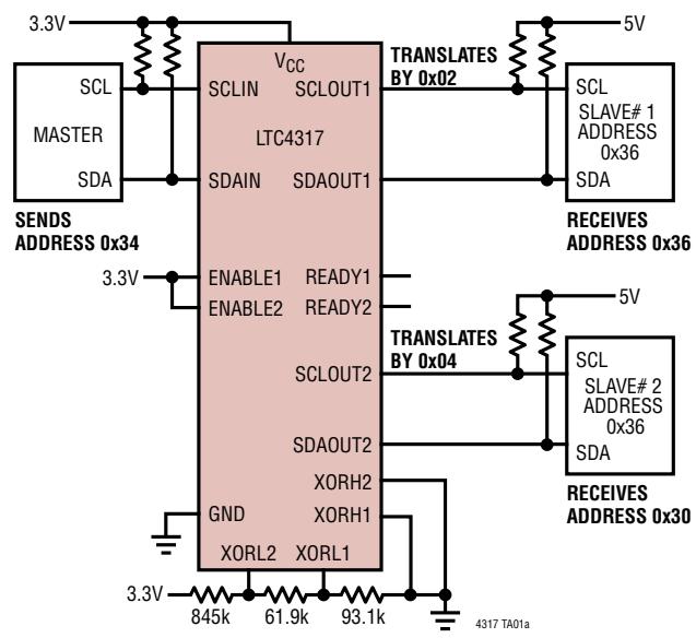
The LTC®4317 enables the hardwired address of one or more I2C or SMBus slave device to be translated to a different address. This allows slaves with the same hardwired address to coexist on the same bus. Only discrete resistors are needed to select the new address and no software programming is required. Up to 127 different address translations are available.
The LTC4317 incorporates a pass-through mode which disables the address translation and allows general call addressing by the master. The LTC4317 is designed to automatically recover from abnormal bus conditions like bus stuck low or premature STOP bits.
The LTC4317 has two output channels for two different sets of slaves. The input channels are tied together to a common set of pins to reduce the pin count and package size.
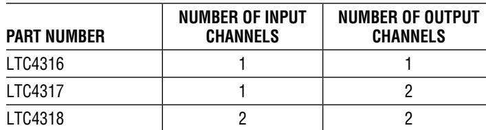
| PART NUMBER | NUMBER OF INPUT CHANNELS | NUMBER OF OUTPUT CHANNELS |
| LTC4316 | 1 | 1 |
| LTC4317 | 1 | 2 |
| LTC4318 | 2 | 2 |
L, LT, LTC, LTM, Linear Technology and the Linear logo are registered trademarks of Linear Technology Corporation. All other trademarks are the property of their respective owners. Protected by U.S. Patents, including 6356140, 6650174, 7032051, 7478286. Patent pending.
Typical Application
16-LEAD (5mm × 3mm) PLASTIC DFN
Absolute Maximum Ratings
(Notes 1, 2) Input Supply Voltage $\mathsf { V } _ { \mathsf { C } \mathsf { C } }$ . –0.3V to 6V Input Voltages ENABLEn.... . –0.3V to 6V XORLn, XORHn ..–0.3V to $\mathsf { V } _ { \mathsf { C C } } + 0 . 3 \mathsf { V }$ Output Voltages READYn ..... . –0.3V to 6V Output Currents READYn, SDAOUTn.. .50mA Input/Output Voltages SCLIN, SCLOUTn, SDAIN, SDAOUTn............ –0.3V to 6V Operating Temperature Range LTC4317C . $0 %$ to $7 0 %$ LTC4317I . $- 4 0 %$ to $8 5 ^ { \circ } \complement$ Storage Temperature Range .... $- 6 5 ^ { \circ } 0$ to $1 5 0 %$
Pin Configuration
Order Information
| LEAD FREE FINISH | TAPE AND REEL | PART MARKING* | PACKAGE DESCRIPTION | TEMPERATURE RANGE |
| LTC4317CDHC#PBF | LTC4317CDHC#TRPBF | 4317 | 16-Lead (5mm × 3mm) Plastic DFN | 0°C to 70°C |
| LTC4317IDHC#PBF | LTC4317IDHC#TRPBF | 4317 | 16-Lead (5mm × 3mm) Plastic DFN | -40°C to 85°C |
Consult LTC Marketing for parts specified with wider operating temperature ranges. *The temperature grade is identified by a label on the shipping container. For more information on lead free part marking, go to: http://www.linear.com/leadfree For more information on tape and reel specifications, go to: http://www.linear.com/tapeandreel/. Some packages are available in 500 unit reels through designated sales channels with #TRMPBF suffix.
Note 2: All currents into pins are positive and all voltages are referenced to GND unless otherwise indicated. Note 3: Guaranteed by design and not tested.
SCLIN, SDAIN, SCLOUT, SDAOUT
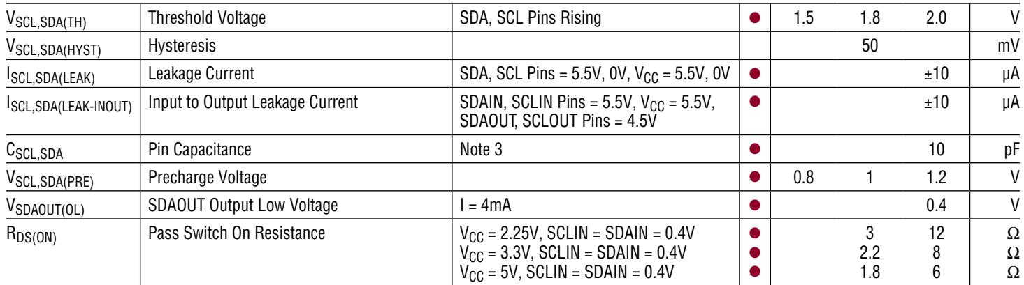
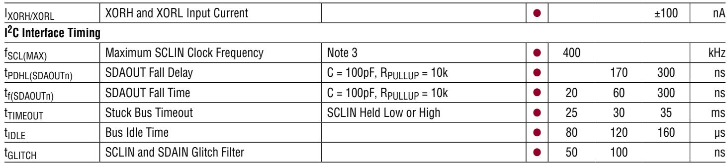
Electrical Characteristics The l denotes the specifications which apply over the full operating temperature range, otherwise specifications are at $\mathsf { T } _ { \mathsf { A } } = 2 5 ^ { \circ } \mathsf { C } . \mathsf { V } _ { \mathsf { C C } } = 3 . 3 \mathsf { V }$ , unless otherwise specified.
| SYMBOL | PARAMETER | CONDITIONS | MIN | TYP | MAX | UNITS | |
| Supply | |||||||
| $V_{CC}$ | Input Supply Range | ● | 2.25 | 5.5 | V | ||
| $I_{CC}$ | Input Supply Current | ENABLE = 3.3V, SCLIN = SDAIN = 0V | ● | 0.8 | 2 | mA | |
| ENABLE = 0V, SCLIN = SDAIN = 0V | ● | 350 | 800 | μA | |||
| $V_{CC(UVLO)}$ | $V_{CC}$ Supply Undervoltage Lockout | $V_{CC}$ Rising | ● | 1.9 | 2.1 | 2.2 | V |
| $V_{CC(HYST)}$ | $V_{CC}$ Supply Undervoltage Lockout Hysteresis | 100 | mV | ||||
| $V_{ENABLE(TH)}$ | ENABLE Threshold Voltage | Enable Rising | ● | 1 | 1.4 | 1.8 | V |
| $V_{ENABLE(HYST)}$ | ENABLE Hysteresis | 50 | mV | ||||
| $I_{ENABLE(LEAK)}$ | ENABLE Input Current | ● | ±1 | μA | |||
| $V_{READY(OL)}$ | READY Output Low Voltage | I = 3mA | ● | 0.4 | V | ||
| $I_{READY(OH)}$ | READY Off Leakage Current | $V_{CC} = V_{READY} = 5.5V$ | ● | ±5 | μA |
| $V_{SCL,SDA(TH)}$ | Threshold Voltage | SDA, SCL Pins Rising | ● | 1.5 | 1.8 | 2.0 | V |
| $V_{SCL,SDA(HYST)}$ | Hysteresis | 50 | mV | ||||
| $I_{SCL,SDA(LEAK)}$ | Leakage Current | SDA, SCL Pins = 5.5V, 0V, $V_{CC}$ = 5.5V, 0V | ● | ±10 | μA | ||
| $I_{SCL,SDA(LEAK-INOUT)}$ | Input to Output Leakage Current | SDAIN, SCLIN Pins = 5.5V, $V_{CC}$ = 5.5V, SDAOUT, SCLOUT Pins = 4.5V | ● | ±10 | μA | ||
| $C_{SCL,SDA}$ | Pin Capacitance | Note 3 | ● | 10 | pF | ||
| $V_{SCL,SDA(PRE)}$ | Precharge Voltage | ● | 0.8 | 1 | 1.2 | V | |
| $V_{SDAOUT(OL)}$ | SDAOUT Output Low Voltage | I = 4mA | ● | 0.4 | V | ||
| $R_{DS(ON)}$ | Pass Switch On Resistance | $V_{CC}$ = 2.25V, SCLIN = SDAIN = 0.4V | ● | 3 | 12 | Ω | |
| $V_{CC}$ = 3.3V, SCLIN = SDAIN = 0.4V | ● | 2.2 | 8 | Ω | |||
| $V_{CC}$ = 5V, SCLIN = SDAIN = 0.4V | ● | 1.8 | 6 | Ω | |||
| IXORH/XORL | XORH and XORL Input Current | ● | ±100 | nA | |||
| I2C Interface Timing | |||||||
| fSCL(MAX) | Maximum SCLIN Clock Frequency | Note 3 | ● | 400 | kHz | ||
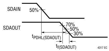
| tPDHL(SDAOUTn) | SDAOUT Fall Delay | C = 100pF, RPULLUP = 10k | ● | 170 | 300 | ns | |
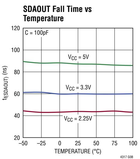
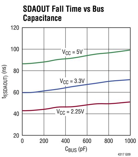
| tf(SDAOUTn) | SDAOUT Fall Time | C = 100pF, RPULLUP = 10k | ● | 20 | 60 | 300 | ns |
| tTIMEOUT | Stuck Bus Timeout | SCLIN Held Low or High | ● | 25 | 30 | 35 | ms |
| tIDLE | Bus Idle Time | ● | 80 | 120 | 160 | μs | |
| tGLITCH | SCLIN and SDAIN Glitch Filter | ● | 50 | 100 | ns | ||
Note 1: Stresses beyond those listed under Absolute Maximum Ratings may cause permanent damage to the device. Exposure to any Absolute Maximum Rating condition for extended periods may affect device reliability and lifetime.
Timing Diagram
Typical Performance Characteristics
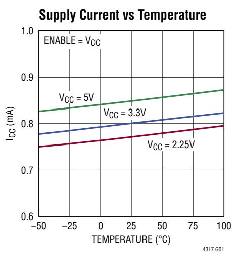
$T _ { A } = 2 5 ^ { \circ } \widehat { \mathbf { 0 } } ,$ $\mathtt { V } _ { \mathtt { C } \mathtt { C } } = 3 . 3 \mathtt { V }$ unless otherwise noted.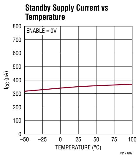
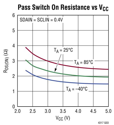
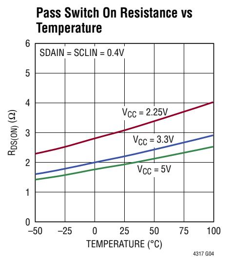
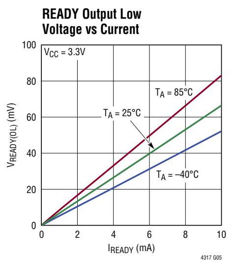
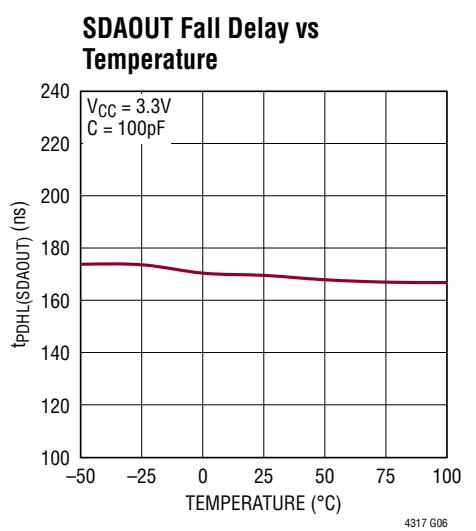
Typical Performance Characteristics
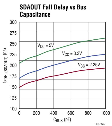
$T _ { A } = 2 5 ^ { \circ } \mathbf { C } ,$ $\mathtt { V } _ { \mathtt { C } \mathtt { C } } = 3 . 3 \mathtt { V }$ unless otherwise noted.
Pin Functions
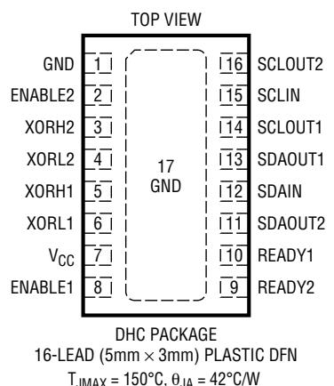
XORL1/XORL2: Translator XOR Lower Nibble Configuration Input. The DC voltage at this pin configures the lower 4-bit nibble of the address translation byte. Tie the pin to an external resistive divider connected between $\mathsf { V } _ { \mathsf { C C } }$ and GND to set the desired DC voltage.
XORH1/XORH2: Translator XOR Upper Nibble Configuration Input. The DC voltage at this pin configures the upper 3-bit nibble of the address translation byte. Tie the pin to an external resistive divider connected between $\mathsf { V } _ { \mathsf { C C } }$ and GND to set the desired DC voltage. Connect this pin to $\mathsf { V } _ { \mathsf { C C } }$ to activate pass-through mode. See Application Information section for more details.
ENABLE1/ENABLE2: Enable Input. If ENABLE pin is low, the address translation is disabled, SDAIN is disconnected from SDAOUT, and SCLIN is disconnected from SCLOUT. A low to high transition on ENABLE restarts the configuration of the address translation byte and also enables the address translation. Connect to $\mathsf { V } _ { \mathsf { C C } }$ if unused.
Exposed Pad: Exposed pad may be left open or connected to device GND.
GND: Device Ground.
READY1/READY2: Ready Status Output. This is an open drain output to indicate that the device is ready for address translation. The pin releases high when the LTC4317 has completed configuration of the address translation byte,
SDAIN is connected to SDAOUT and SCLIN is connected to SCLOUT. Connect a pull-up resistor, typically 10k, from this pin to the bus pull-up supply. Leave open or tie to GND if unused.
SCLIN: Input Bus Clock Input and Output. Connect this pin to the SCL line on the master side. An external pull-up resistor or current source is required.
SCLOUT1/SCLOUT2: Output Bus Clock Input and Output. Connect this pin to the SCL line on the slave side. An external pull-up resistor or current source is required. Connect to V through a pull-up resistor if unused.
SDAIN: Input Bus Data Input and Output. Connect this pin to the SDA line on the master side. An external pull-up resistor or current source is required.
SDAOUT1/SDAOUT2: Output Bus Data Input and Output. Connect this pin to the SDA line on the slave side. An external pull-up resistor or current source is required. Connect to $\mathsf { V } _ { \mathsf { C C } }$ through a pull-up resistor if unused.
VCC: Power Supply Input (2.25V to 5.5V). If the supply voltages for the input and output buses are different, connect this pin to the lower supply. If the input and output supplies have the same nominal value and with tolerance less than or equal to ±10%, connect $\mathsf { V } _ { \mathsf { C } } { \mathsf { c } }$ to either supply. Bypass with at least 0.1µF to GND.
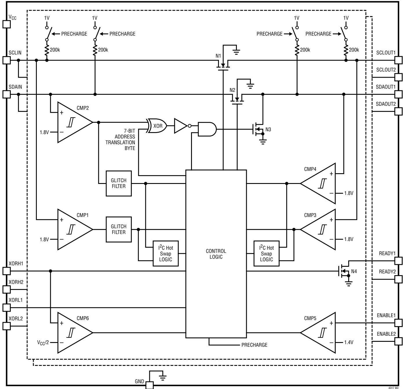
Block Diagram
Operation
The LTC4317 is an $| 2 0 \rangle$ /SMBus address translator. It bridges two segments of an $| ^ { 2 } 0$ bus, reading incoming addresses on the master side and retransmitting them to the slave side with the 7-bit $\mathsf { I 2 0 }$ addresses translated in real time. This allows multiple $| ^ { 2 } 0$ devices with the same address to be connected to the same bus without interference. The translated addresses are configured with external resistors, and no extra software is required. An ENABLE pin allows bus segments to be enabled and disabled, and the LTC4317 allows hot swapping isolated bus segments together.
Figure 1 shows an $\mathsf { I 2 0 }$ master connected to the input bus of the LTC4317 (SCLIN and SDAIN). The slave devices requiring address translation are connected to the output bus of the LTC4317 (SCLOUT and SDAOUT). Any other slave devices that do not require address translation are placed together with the master on the input bus of the LTC4317. Two switches (N1 and N2) inside the LTC4317 connect the input bus to the output bus. N1 connects SCLIN to SCLOUT while N2 connects SDAIN to SDAOUT.
In most conditions, N1 and N2 stay on so that the input and output buses are connected.
Translation starts when the master issues a START bit (SDAIN goes low while SCLIN is high). The LTC4317 turns off N2 to disconnect SDAIN from SDAOUT. As the master sends the address byte, the LTC4317 translates the incoming address at the SDAIN pin to a new address at the SDAOUT pin by XORing each incoming bit with a user-configurable translation byte, one bit at a time. N3 turns on and off to send out the new address to the SDAOUT pin. Once all 7 bits of the address are processed, the LTC4317 turns on N2 again to reconnect SDAIN to SDAOUT. The master then transmits the R/W bit directly to the slave. If the new, translated address on SDAOUT matches the slave’s address, the slave pulls SDAOUT low to acknowledge (ACK bit). N2 remains on and the rest of the data bytes are transmitted unmodified between the master and slave. The address translation process restarts when the master issues a new START bit.
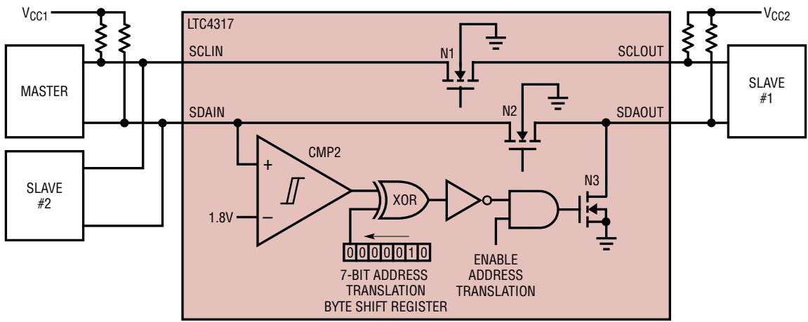
Figure 1. Basic Functions of the LTC4317
Operation
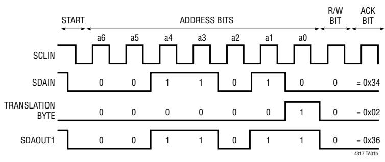
Figure 2 shows typical waveforms for the circuit on the front page. In this example, the master transmits address 0x34 while the slave is configured to respond to address 0x36. The resistive dividers at the XORL and XORH pins are configured to generate an address translation byte of 0x02.
Note that in this example, the 8-bit hexadecimal address format (with $\mathsf { R } / \mathsf { W } = 0 )$ is used. 7-bit addresses are also commonly found in $| ^ { 2 } \dot { 0 }$ device documentation. Make sure to use the correct format when calculating the address translation byte. Table 1 shows examples of both formats.
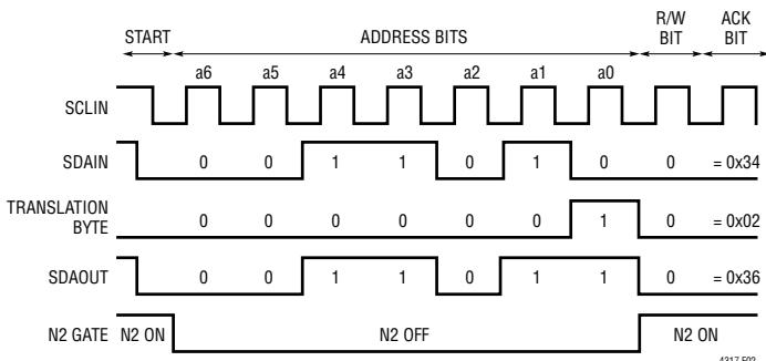
Figure 2. Basic Address Translation Waveforms
Table 1.
| DESCRIPTION | BINARY ADDRESS | 7-BIT HEX ADDRESS WITHOUT R/W | 8-BIT HEX ADDRESS WITH R/W = 0 | |||||||
| a6 | a5 | a4 | a3 | a2 | a1 | a0 | R/W | |||
| Input Address from SDAIN | 0 | 0 | 1 | 1 | 0 | 1 | 0 | 0 | 0x1A | 0x34 |
| Translation Byte | 0 | 0 | 0 | 0 | 0 | 0 | 1 | 0 | 0x01 | 0x02 |
| Output Address to SDAOUT | 0 | 0 | 1 | 1 | 0 | 1 | 1 | 0 | 0x1B | 0x36 |
Operation
System Configurations
There are several ways that individual slaves or banks of slaves can be connected to an LTC4317. In Figure 3, each slave is paired with one channel of the LTC4317. This configuration allows for maximum flexibility in allocating the bus addresses. Both read and write operations and all protocols supported by the LTC4317 are allowed. Figure 4 shows two slaves with different hardwired addresses translated to two different addresses using one channel of the LTC4317 and a common translation byte. A program is available to help the user visualize an $\mathsf { I } 2 \mathsf { C }$ bus with the LTC4317; this program can be found in the following link:
www.linear.com/TranslatorTool
Setting the Translation Byte
When the LTC4317 is first powered up or any time a rising edge is detected on the ENABLE pin, the LTC4317 reads the voltages at the XORH and XORL pins to determine the
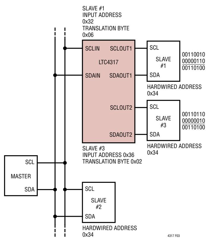
Figure 3. Two Independent Address Translation
7-bit translation byte. These voltages are referenced to $\mathsf { V } _ { \mathsf { C } \mathsf { C } }$ so a resistive divider at each of these pins is the most convenient way to set the voltages. The required translation byte can be determined by taking the bitwise XOR of the slave’s original address and the desired input address.
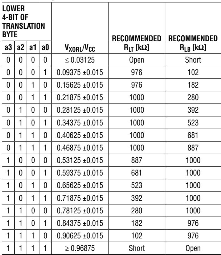
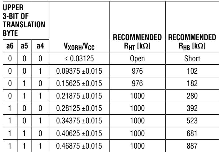
The voltages at the XORH and XORL pins configure the translation byte. The XORL voltage configures the lower 4 translation bits (excluding the R/W bit), while the XORH voltage configures the upper 3 translation bits. Tables 2 and 3 show the recommended resistive divider values. $\mathsf { R } _ { \mathsf { U } }$ and $\mathsf { R } _ { \mathsf { L B } }$ are the top and bottom resistors connected to XORL, while $\mathsf { R } _ { \mathsf { H T } }$ and $\mathsf { R } _ { \mathsf { H B } }$ are the top and bottom resistors connected to XORH (Figure 5). Use 1% tolerance resistors for $\mathsf { R } _ { \mathsf { U } }$ $\mathsf { R } _ { \mathsf { L E } }$ , $\mathsf { R } _ { \mathsf { H T } }$ and $\mathsf { R } _ { \mathsf { H B } }$
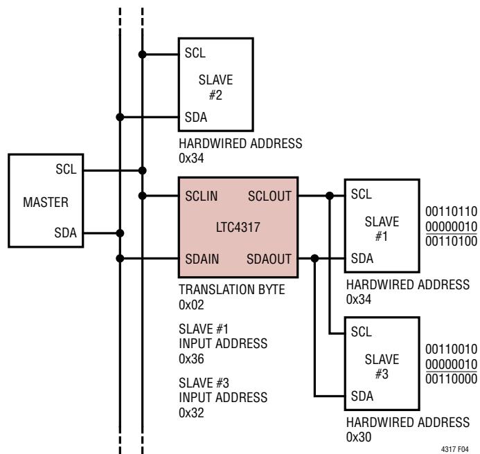
Figure 4. Two Slaves Sharing One Channel of LTC4317
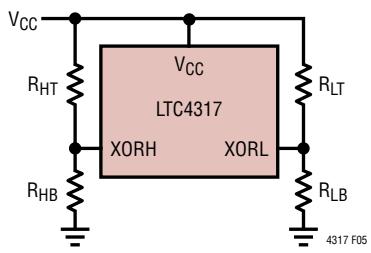
Figure 5. Address Translation Byte Configuration Resistors
Operation
Table 2. Setting the Resistive Divider at XORL
| LOWER4-BIT OFTRANSLATIONBYTE | $V_{XORL}/V_{CC}$ | RECOMMENDED $R_{LT}$ [kΩ] | RECOMMENDED $R_{LB}$ [kΩ] | |||
| a3 | a2 | a1 | a0 | |||
| 0 | 0 | 0 | 0 | ≤ 0.03125 | Open | Short |
| 0 | 0 | 0 | 1 | 0.09375 ±0.015 | 976 | 102 |
| 0 | 0 | 1 | 0 | 0.15625 ±0.015 | 976 | 182 |
| 0 | 0 | 1 | 1 | 0.21875 ±0.015 | 1000 | 280 |
| 0 | 1 | 0 | 0 | 0.28125 ±0.015 | 1000 | 392 |
| 0 | 1 | 0 | 1 | 0.34375 ±0.015 | 1000 | 523 |
| 0 | 1 | 1 | 0 | 0.40625 ±0.015 | 1000 | 681 |
| 0 | 1 | 1 | 1 | 0.46875 ±0.015 | 1000 | 887 |
| 1 | 0 | 0 | 0 | 0.53125 ±0.015 | 887 | 1000 |
| 1 | 0 | 0 | 1 | 0.59375 ±0.015 | 681 | 1000 |
| 1 | 0 | 1 | 0 | 0.65625 ±0.015 | 523 | 1000 |
| 1 | 0 | 1 | 1 | 0.71875 ±0.015 | 392 | 1000 |
| 1 | 1 | 0 | 0 | 0.78125 ±0.015 | 280 | 1000 |
| 1 | 1 | 0 | 1 | 0.84375 ±0.015 | 182 | 976 |
| 1 | 1 | 1 | 0 | 0.90625 ±0.015 | 102 | 976 |
| 1 | 1 | 1 | 1 | ≥ 0.96875 | Short | Open |
Table 3. Setting the Resistive Divider at XORH
| UPPER3-BIT OFTRANSLATIONBYTE | $V_{XORH}/V_{CC}$ | RECOMMENDED $R_{HT}$ [kΩ] | RECOMMENDED $R_{HB}$ [kΩ] | ||
| a6 | a5 | a4 | |||
| 0 | 0 | 0 | ≤ 0.03125 | Open | Short |
| 0 | 0 | 1 | 0.09375 ±0.015 | 976 | 102 |
| 0 | 1 | 0 | 0.15625 ±0.015 | 976 | 182 |
| 0 | 1 | 1 | 0.21875 ±0.015 | 1000 | 280 |
| 1 | 0 | 0 | 0.28125 ±0.015 | 1000 | 392 |
| 1 | 0 | 1 | 0.34375 ±0.015 | 1000 | 523 |
| 1 | 1 | 0 | 0.40625 ±0.015 | 1000 | 681 |
| 1 | 1 | 1 | 0.46875 ±0.015 | 1000 | 887 |
For example, if $\mathsf { R } _ { \mathsf { L } \mathsf { T } } = 9 7 6 \mathsf { k } ,$ $\mathsf { R } _ { \mathsf { L B } } = 1 0 2 \mathsf { k }$ $\mathsf { R } _ { \mathsf { H T } } = 1 0 0 0 \mathsf { k } ,$ , and $\mathsf { R } _ { \mathsf { H B } } = 2 8 0 \mathsf { k }$ , the lower 4 translation bits are 0001b and the upper 3 bits are 011b. The 8-bit hexadecimal address translation byte is obtained by adding a 0 as the LSB,
which gives 0110 0010b or 0x62. If the configuration voltages at XORL and XORH pins are the same, they can be tied together and connected to a single resistive divider. Alternatively, three resistors can be used to configure the XORL and XORH pins (Figure 6). Use the following procedure to calculate the value of the three resistors:
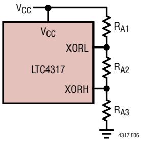
Figure 6. Address Translation Byte Configuration Using Three Resistors
First choose a total resistance value RTOTAL
$$
R _ {A 3} = R _ {T O T A L} \bullet (V _ {X O R H} / V _ {C C})
$$
$$
R _ {A 2} = (R _ {T O T A L} \bullet V _ {X O R L} / V _ {C C}) - R A 3
$$
$$
R _ {A 1} = R _ {T O T A L} - R _ {A 3} - R _ {A 2}
$$
Use 1% tolerance resistors for $\mathsf { R } _ { \mathsf { A } 1 } , \mathsf { R } _ { \mathsf { A } 2 }$ and $\mathsf { R } _ { \mathsf { A } 3 }$ .
Once the XORL and XORH pins are read, the LTC4317 turns on switches N1 and N2, connecting the input and output, and the READY pin goes high to indicate that the LTC4317 is ready to start address translation.
The address translation byte can be changed during operation by changing the XORH and XORL voltages and toggling the ENABLE pin (high-low-high). This triggers the LTC4317 to re-read the XORL and XORH voltages.
Enable/UVLO
If the ENABLE pin is driven below VENABLE(TH) or if $\mathsf { V } _ { \mathsf { C C } }$ is below the UVLO threshold, the LTC4317 shuts down. The internal shift register storing the address translation byte is cleared, address translation is disabled, switches N1, N2 and N3 are off, the READY pin is pulled low and the quiescent current drops to 350µA.
Operation
Precharge and Hot Swap
When the LTC4317 is first powered on, switches N1 and N2 are initially off. This allows a LTC4317 and its connected slaves to be hot swapped onto an active $| ^ { 2 } 0$ bus. Internal precharge circuitry initially sets the bus lines to 1V through a 200k resistor, minimizing disturbance to an active bus when the LTC4317 is connected. The LTC4317 keeps N1 and N2 off until ENABLE goes high, the XORL/ XORH pins are read, and both sides of the $| ^ { 2 } 0$ bus are idle (indicated either by a STOP bit or all bus pins high for longer than 120µs). Once these conditions are met, N1 and N2 turn on, and the READY pin goes high to indicate that the LTC4317 is ready to start address translation.
Pass-Through Mode
If the master wants to communicate with the slave using the general call address, it can temporarily disable address translation by pulling XORH high. This disables address translation and keeps N1 and N2 on regardless of the activity on the buses. Any translation that may be in progress is stopped immediately when XORH goes high.
Extra Transitions on SDAOUT
In an I2C/SMBus system, the master changes the state of the SDA line when SCL is low. The LTC4317 also advances the address translation byte shift register when the SCLIN is low. The translation byte transitions occur approximately 100ns after the falling edge of SCLIN. If the SDAIN transitions sent by the master do not coincide exactly with the LTC4317 address translation bit transitions, an extra transition on SDAOUT may appear (Figure 7). These extra SDA transitions are like glitches similar to those occurring during normal Acknowledge bit transitions and do not pose problems in the system because devices on the bus latch SDA data only when SCL is high.
Level Translation and Supply Voltage Matching
The LTC4317 can operate with different supply voltages on the input and output bus, and it will level shift the voltages on the SCLIN, SDAIN, SCLOUT, and SDAOUT pins to match the supply voltage at each side. $\mathsf { V } _ { \mathsf { C C } }$ must be powered from the lower of the two supply voltages for level shifting to operate correctly. For example, if the input bus is powered by a 5V supply and the output bus is powered by a 3.3V supply, the LTC4317 VCC pin must be connected to the 3.3V supply as shown in Figure 8.
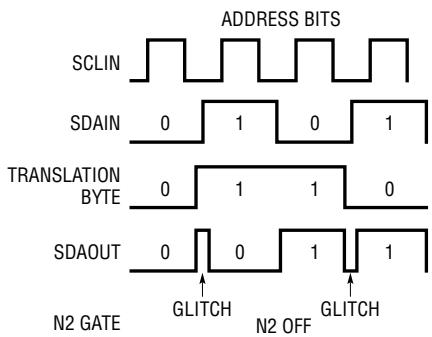
Figure 7. Extra Transitions on SDAOUT While SCL Is Low
If the LTC4317 supply pin is connected to the higher bus supply, current may flow through the switches N1 and N2 to the bus with lower supply. If the voltage difference
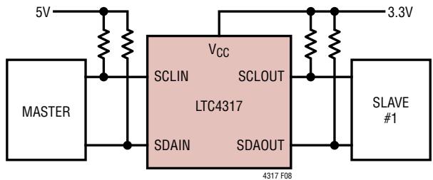
Figure 8. A 5V to 3.3V Level Translation Application
is less than 1V, this current is limited to less than 10µA. This allows the input and output buses to be connected to nominally identical supplies that may have up ±10% tolerance, and the LTC4317 $\mathsf { V } _ { \mathsf { C C } }$ pin can be connected to either supply.
Extra START and STOP Bits
During normal operation, an $| ^ { 2 } 0$ master should not issue a START or ${ \mathsf { S T O P } }$ bit within a data byte. $| 2 0 \rangle$ slave behavior when such a command is received can be unpredictable. The LTC4317 will recover automatically when an unexpected START or STOP is received during the address byte; however, depending on the state of the translating bits, it may convert START bits to STOP bits and vice versa, causing unexpected slave behavior.
Operation
If a START bit is received during the address byte when the active translating bit is $a ^ { n } 1 ^ { * }$ the slave device will see a STOP bit. This will typically reset the slave and cause it to miss the remainder of the transmission. If the START bit is received while the active translating bit is a $" 0 "$ , the START passes through the LTC4317 unchanged. The slave will react in the same way it would if the LTC4317 was not present, and will typically reset when the master next issues a STOP bit. In both cases, the LTC4317 automatically resets at the next STOP bit and the next message will be transmitted normally.
If a STOP bit is received during the address byte, the LTC4317 will abort the address translation and ensure that a STOP bit is issued at SDAOUT to reset the slave. If the active translating bit is $\textsf { a } ^ { \mathfrak { n } }$ when the STOP arrives, it is not modified, and the slave will see the STOP and typically reset. If the active translating bit is $a " 1 "$ when the STOP arrives, the slave device will see a START bit. This might leave the slave in an indeterminate state, so the LTC4317 briefly disconnects the slave from the master, adds a short delay, and then generates a STOP bit at the SDAOUT pin (Figure 9). It then reconnects the busses and waits for a START bit to begin the next transmission. Again, in both cases, the LTC4317 automatically resets and the next message will be transmitted normally.
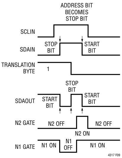
Figure 9. Stop Bit within Address Byte when Address Translation Byte Is 1
Stuck Bus Timeout
During the address translation, if SCLIN stays low or high for more than 30ms without any transitions, the LTC4317 will abort the address translation and reconnect SDAIN to SDAOUT. It will then wait for a START bit to start a new address translation. This prevents any bus stuck low/ high conditions from permanently disconnecting SDAIN from SDAOUT.
Supported Protocols
The LTC4317 is designed to support most $| ^ { 2 } 0$ and SMBus message protocols. The only exceptions are protocols that use pre-assigned addresses on the slave side of the bus.
Supported $| ^ { 2 } 0$ and SMBus Protocols: Send/Receive Byte Write Byte/Word Read Byte/Word Process Call Block Write/Read Block Write-Block Read Process Call Extended Read and Write Commands General Call $( | ^ { 2 } 0 \rangle$ Only) Start Byte $( | ^ { 2 } 0 \rangle$ Only) PMBus (without PEC) Unsupported $| ^ { 2 } 0$ Protocols: 10-Bit Addressing Device ID Ultra Fast-Mode $| ^ { 2 } 0$ Bus Protocol Unsupported SMBus Protocols: SMBus Host Notify Address Resolution Protocol (ARP) Parity Error Code (PEC) Alert Response Address (ARA) PMBus (with PEC)
Typical Applications
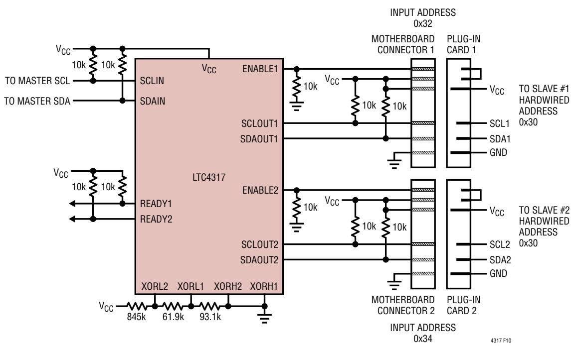
Figure 10. LTC4317 with Address Translation Byte of 0x02 and 0x04
MOLD FLASH. MOLD FLASH, IF PRESENT, SHALL NOT EXCEED 0.15mm ON ANY SIDE
Package Description
Please refer to http://www.linear.com/product/LTC4317#packaging for the most recent package drawings.
DHC Package 16-Lead Plastic DFN (5mm × 3mm) (Reference LTC DWG # 05-08-1706 Rev Ø)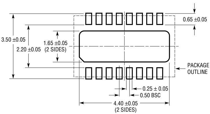
RECOMMENDED SOLDER PAD PITCH AND DIMENSIONS
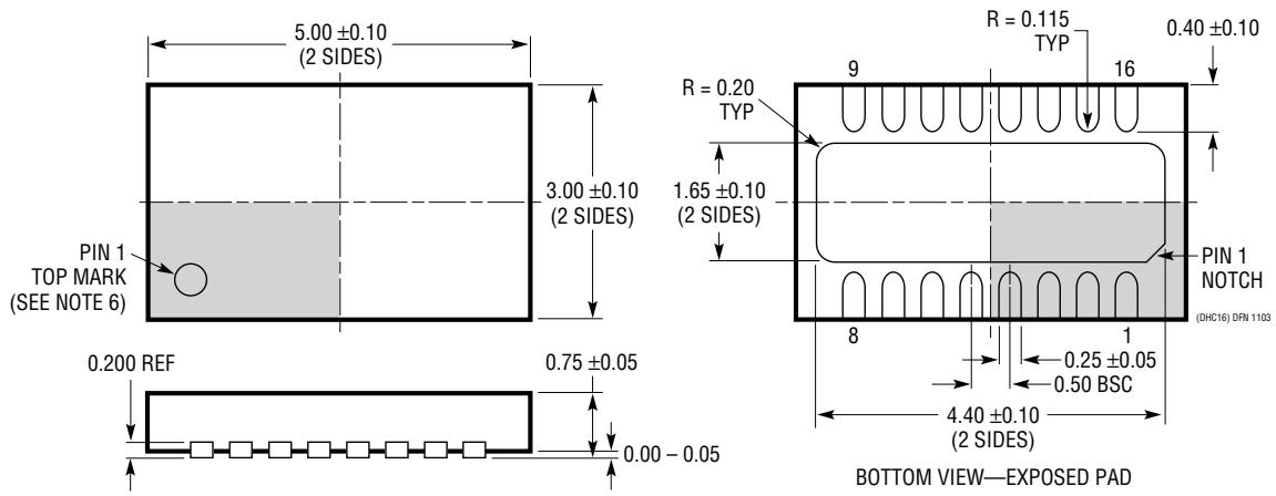
DRAWING PROPOSED TO BE MADE VARIATION OF VERSION (WJED-1) IN JEDEC
DRAWING NOT TO SCALE
ALL DIMENSIONS ARE IN MILLIMETERS
DIMENSIONS OF EXPOSED PAD ON BOTTOM OF PACKAGE DO NOT INCLUDE
EXPOSED PAD SHALL BE SOLDER PLATED
SHADED AREA IS ONLY A REFERENCE FOR PIN 1 LOCATION ON THE TOP AND BOTTOM OF PACKAGE
Revision History
| REV | DATE | DESCRIPTION | PAGE NUMBER |
| A | 10/15 | Minor edits | 4, 5 |
4317fa
Typical Application
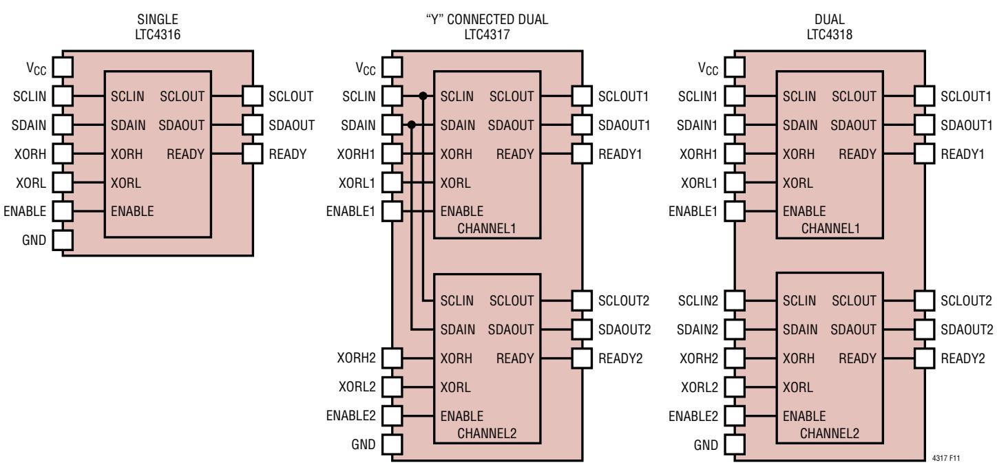
Figure 11. Comparison Between LTC4316/LTC4317/LTC4318
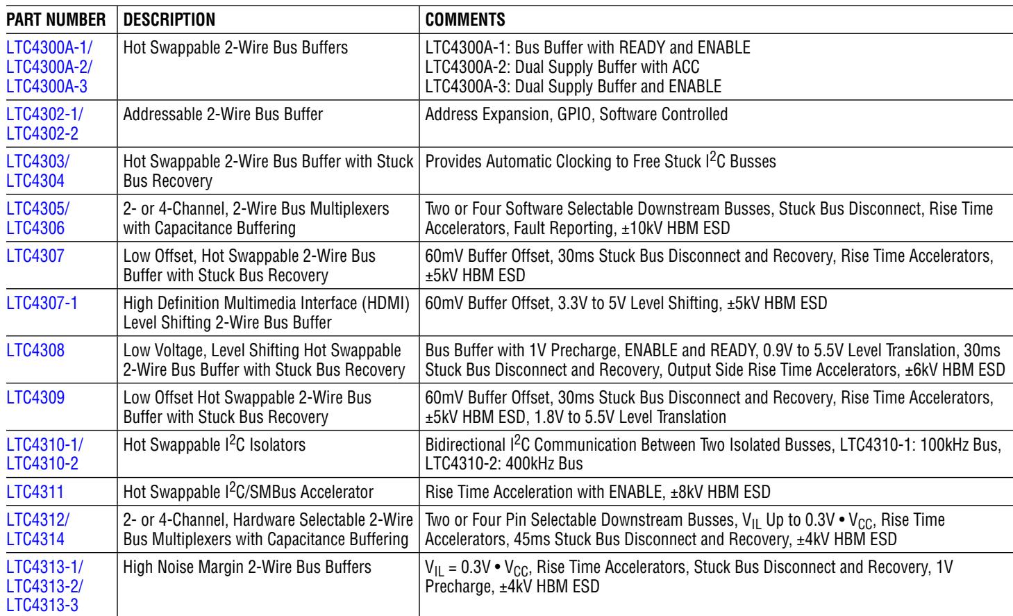
Related Parts
| PART NUMBER | DESCRIPTION | COMMENTS |
| LTC4300A-1/LTC4300A-2/LTC4300A-3 | Hot Swappable 2-Wire Bus Buffers | LTC4300A-1: Bus Buffer with READY and ENABLELTC4300A-2: Dual Supply Buffer with ACCLTC4300A-3: Dual Supply Buffer and ENABLE |
| LTC4302-1/LTC4302-2 | Addressable 2-Wire Bus Buffer | Address Expansion, GPIO, Software Controlled |
| LTC4303/LTC4304 | Hot Swappable 2-Wire Bus Buffer with Stuck Bus Recovery | Provides Automatic Clocking to Free Stuck $I^{2}C$ Busses |
| LTC4305/LTC4306 | 2- or 4-Channel, 2-Wire Bus Multiplexers with Capacitance Buffering | Two or Four Software Selectable Downstream Busses, Stuck Bus Disconnect, Rise Time Accelerators, Fault Reporting, ±10kV HBM ESD |
| LTC4307 | Low Offset, Hot Swappable 2-Wire Bus Buffer with Stuck Bus Recovery | 60mV Buffer Offset, 30ms Stuck Bus Disconnect and Recovery, Rise Time Accelerators, ±5kV HBM ESD |
| LTC4307-1 | High Definition Multimedia Interface (HDMI) Level Shifting 2-Wire Bus Buffer | 60mV Buffer Offset, 3.3V to 5V Level Shifting, ±5kV HBM ESD |
| LTC4308 | Low Voltage, Level Shifting Hot Swappable 2-Wire Bus Buffer with Stuck Bus Recovery | Bus Buffer with 1V Precharge, ENABLE and READY, 0.9V to 5.5V Level Translation, 30ms Stuck Bus Disconnect and Recovery, Output Side Rise Time Accelerators, ±6kV HBM ESD |
| LTC4309 | Low Offset Hot Swappable 2-Wire Bus Buffer with Stuck Bus Recovery | 60mV Buffer Offset, 30ms Stuck Bus Disconnect and Recovery, Rise Time Accelerators, ±5kV HBM ESD, 1.8V to 5.5V Level Translation |
| LTC4310-1/LTC4310-2 | Hot Swappable $I^{2}C$ Isolators | Bidirectional $I^{2}C$ Communication Between Two Isolated Busses, LTC4310-1: 100kHz Bus, LTC4310-2: 400kHz Bus |
| LTC4311 | Hot Swappable $I^{2}C/SMBus$ Accelerator | Rise Time Acceleration with ENABLE, ±8kV HBM ESD |
| LTC4312/LTC4314 | 2- or 4-Channel, Hardware Selectable 2-Wire Bus Multiplexers with Capacitance Buffering | Two or Four Pin Selectable Downstream Busses, $V_{IL}$ Up to 0.3V • $V_{CC}$ , Rise Time Accelerators, 45ms Stuck Bus Disconnect and Recovery, ±4kV HBM ESD |
| LTC4313-1/LTC4313-2/LTC4313-3 | High Noise Margin 2-Wire Bus Buffers | $V_{IL} = 0.3V \cdot V_{CC}$ , Rise Time Accelerators, Stuck Bus Disconnect and Recovery, 1V Precharge, ±4kV HBM ESD |
Figures and diagrams from the PDF
Preview the extracted datasheet assets and open any image in a separate tab for closer inspection.








Use this datasheet from any agent
Send the page, markdown, chunks, or search endpoint to ChatGPT, Claude, embedr-app, or your own tooling.