
AD7171
16-Bit Sigma-Delta ADC with SPI Interface
FEATURES
Output data rate: 125 Hz Pin-programmable power-down and reset Status function Internal clock oscillator Current: 135 µA Power supply: 2.7 V to 5.25 V −40°C to +105°C temperature range Package: 10-lead 3 mm × 3 mm LFCSP
INTERFACE
2-wire serial (read-only device) SPI compatible Schmitt trigger on SCLK
APPLICATIONS
Weigh scales
Pressure measurement Industrial process control Portable instrumentation
GENERAL DESCRIPTION
The AD7171 is a very low power, 16-bit, analog-to-digital converter (ADC). It contains a precision, 16-bit, Σ-Δ ADC and an on-chip oscillator. Consuming only 135 µA, the AD7171 is particularly suitable for portable or battery operated products where very low power is a requirement. The AD7171 also has a power-down mode in which the device consumes 5 μA, thus increasing the battery life of the product.
For ease of use, dedicated pins control all of the features of the AD7171. Each time a data read occurs, eight status bits are appended to the 16-bit conversion. These status bits contain a pattern sequence that can be used to confirm the validity of the serial transfer.
FUNCTIONAL BLOCK DIAGRAM
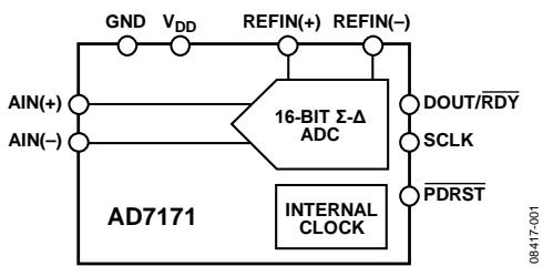
Figure 1.
Table 1.
| $V_{REF} = V_{DD}$ | RMS Noise | P-P Noise | P-P Resolution | ENOB |
| 5 V | 11.5 μV | 76 μV | 16 bits | 16 bits |
| 3 V | 6.9 μV | 45 μV | 16 bits | 16 bits |
The output data rate of the AD7171 is 125 Hz, whereas the settling time is 24 ms. The AD7171 has one differential input and a gain of 1. This is useful in applications where the user needs to use an external amplifier to implement system-specific filtering or gain requirements.
The AD7171 operates with a power supply from 2.7 V to 5.25 V. It is available in a 10-lead LFCSP.
The AD7170 is a 12-bit version of the AD7171. It has the same feature set as the AD7171 and is pin-for-pin compatible.
TABLE OF CONTENTS
Features....1
Interface....1
Applications....1
Functional Block Diagram....1
General Description....1
Revision History....2
Specifications....3
Timing Characteristics....5
Timing Diagrams....5
Absolute Maximum Ratings....6
Thermal Resistance....6
ESD Caution....6
Pin Configuration and Function Descriptions....7
Typical Performance Characteristics....8
Output Noise and Resolution Specifications....9
ADC Circuit Information....10
REVISION HISTORY
6/2016—Rev. B to Rev. C
Change to Figure 14....13
6/2015—Rev. A to Rev. B
Added Table Number; Renumbered Sequentially.... 1
Changed NC Pin (Pin 10) to GND Pin (Pin 10), Figure 5.... 7
4/2013—Rev. 0 to Rev. A
Changes to Filter, Data Rate, and Settling Time Section.... 10
Changes to Temperature System Section.... 13
Updated Outline Dimensions.... 14
Changes to Ordering Guide.... 14
10/2009—Revision 0: Initial Version
Overview .... 10
Filter, Data Rate, and Settling Time.... 10
Gain.... 10
Power-Down/Reset (PDRST).... 10
Analog Input Channel.... 10
Bipolar Configuration.... 10
Data Output Coding.... 11
Reference.... 11
Digital Interface.... 11
Grounding and Layout.... 12
Applications Information.... 13
Temperature System.... 13
Signal Conditioning Circuit.... 13
Outline Dimensions.... 14
Ordering Guide.... 14
SPECIFICATIONS
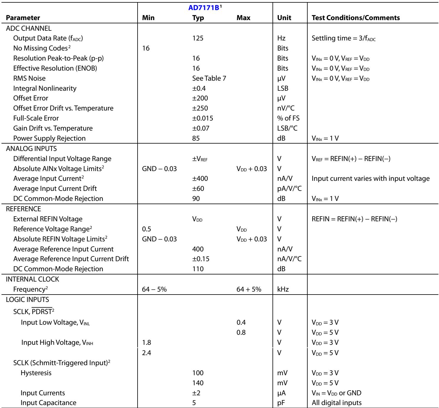
VDD = 2.7 V to 5.25 V, $\mathrm { V } _ { \mathrm { R E F } } = \mathrm { V } _ { \mathrm { D D } } ,$ GND = 0 V, all specifications TMIN to TMAX, unless otherwise noted
Table 2.
| Parameter | AD7171B $^{1}$ | Unit | Test Conditions/Comments | ||
| Min | Typ | Max | |||
| ADC CHANNEL | |||||
| Output Data Rate ( $f_{ADC}$ ) | 125 | Hz | Settling time = 3/ $f_{ADC}$ | ||
| No Missing Codes $^{2}$ | 16 | Bits | |||
| Resolution Peak-to-Peak (p-p) | 16 | Bits | $V_{INx} = 0V, V_{REF} = V_{DD}$ | ||
| Effective Resolution (ENOB) | 16 | Bits | $V_{INx} = 0V, V_{REF} = V_{DD}$ | ||
| RMS Noise | See Table 7 | μV | $V_{INx} = 0V, V_{REF} = V_{DD}$ | ||
| Integral Nonlinearity | ±0.4 | LSB | |||
| Offset Error | ±200 | μV | |||
| Offset Error Drift vs. Temperature | ±250 | nV/°C | |||
| Full-Scale Error | ±0.015 | % of FS | |||
| Gain Drift vs. Temperature | ±0.07 | LSB/°C | |||
| Power Supply Rejection | 85 | dB | $V_{INx} = 1V$ | ||
| ANALOG INPUTS | |||||
| Differential Input Voltage Range | ± $V_{REF}$ | V | $V_{REF} = \text{REFIN}(+) - \text{REFIN}(-)$ | ||
| Absolute AINx Voltage Limits $^{2}$ | GND - 0.03 | $V_{DD} + 0.03$ | V | ||
| Average Input Current $^{2}$ | ±400 | nA/V | Input current varies with input voltage | ||
| Average Input Current Drift | ±60 | pA/V/°C | |||
| DC Common-Mode Rejection | 90 | dB | $V_{INx} = 1V$ | ||
| REFERENCE | |||||
| External REFIN Voltage | $V_{DD}$ | V | REFIN = REFIN(+) - REFIN(-) | ||
| Reference Voltage Range $^{2}$ | 0.5 | $V_{DD}$ | V | ||
| Absolute REFIN Voltage Limits $^{2}$ | GND - 0.03 | $V_{DD} + 0.03$ | V | ||
| Average Reference Input Current | 400 | nA/V | |||
| Average Reference Input Current Drift | ±0.15 | nA/V/°C | |||
| DC Common-Mode Rejection | 110 | dB | |||
| INTERNAL CLOCK | |||||
| Frequency $^{2}$ | 64 - 5% | 64 + 5% | kHz | ||
| LOGIC INPUTS | |||||
| SCLK, $\overline{PDRST}^{2}$ | |||||
| Input Low Voltage, $V_{INL}$ | 0.4 | V | $V_{DD} = 3V$ | ||
| 0.8 | V | $V_{DD} = 5V$ | |||
| Input High Voltage, $V_{INH}$ | 1.8 | V | $V_{DD} = 3V$ | ||
| 2.4 | V | $V_{DD} = 5V$ | |||
| SCLK (Schmitt-Triggered Input) $^{2}$ | |||||
| Hysteresis | 100 | mV | $V_{DD} = 3V$ | ||
| 140 | mV | $V_{DD} = 5V$ | |||
| Input Currents | ±2 | μA | $V_{IN} = V_{DD}$ or GND | ||
| Input Capacitance | 5 | pF | All digital inputs | ||
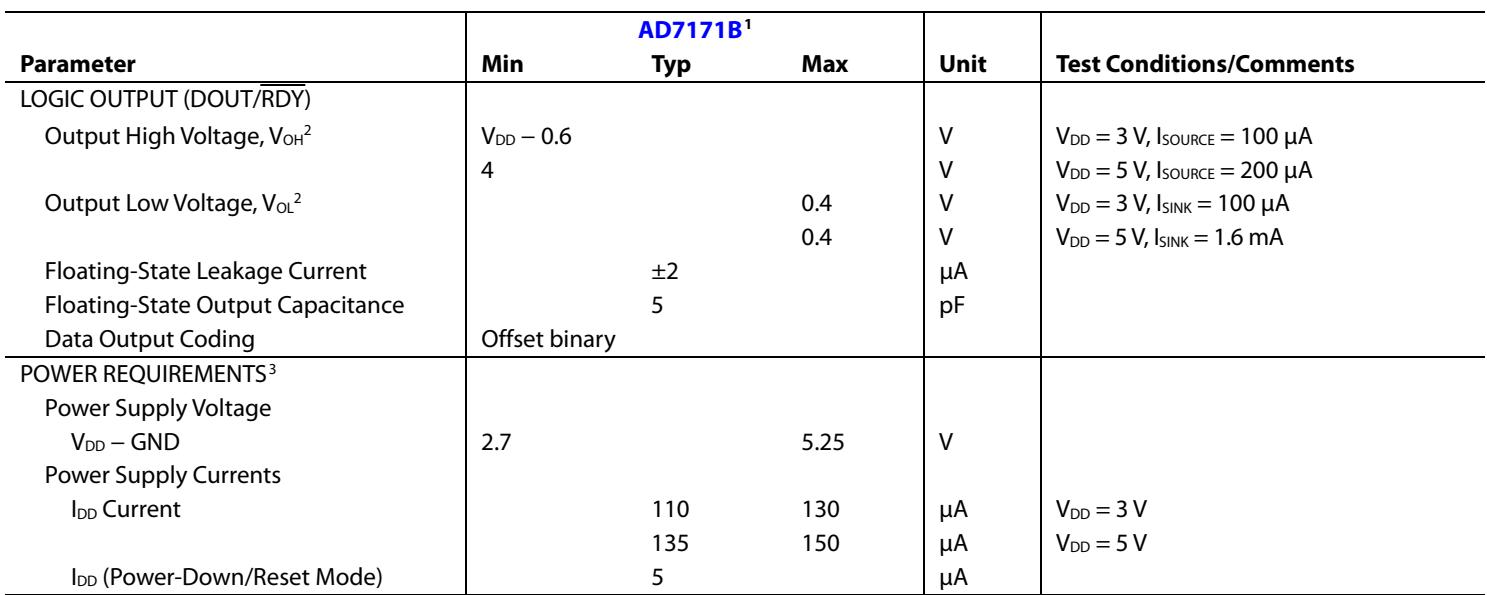
| LOGIC OUTPUT (DOUT/RDY) | |||||
| Output High Voltage, $V_{OH}^{2}$ | $V_{DD} - 0.6$ | V | $V_{DD} = 3\text{ V}, I_{SOURCE} = 100\mu\text{A}$ | ||
| 4 | V | $V_{DD} = 5\text{ V}, I_{SOURCE} = 200\mu\text{A}$ | |||
| Output Low Voltage, $V_{OL}^{2}$ | 0.4 | V | $V_{DD} = 3\text{ V}, I_{SINK} = 100\mu\text{A}$ | ||
| 0.4 | V | $V_{DD} = 5\text{ V}, I_{SINK} = 1.6\text{ mA}$ | |||
| Floating-State Leakage Current | ±2 | μA | |||
| Floating-State Output Capacitance | 5 | pF | |||
| Data Output Coding | Offset binary | ||||
| POWER REQUIREMENTS $^{3}$ | |||||
| Power Supply Voltage | |||||
| $V_{DD} - GND$ | 2.7 | 5.25 | V | ||
| Power Supply Currents | |||||
| $I_{DD}$ Current | 110 | 130 | μA | $V_{DD} = 3\text{ V}$ | |
| 135 | 150 | μA | $V_{DD} = 5\text{ V}$ | ||
| $I_{DD}$ (Power-Down/Reset Mode) | 5 | μA | |||
1 Temperature range is −40°C to +105°C.
3 Digital inputs equal to VDD or GND.
2 Specification is not production tested but is supported by characterization data at initial product release.
| Data Sheet | AD7171 |
TIMING CHARACTERISTICS
$\mathrm { V _ { D D } } = 2 . 7 \ : \mathrm { V }$ to 5.25 V, GND = 0 V, Input Logic $0 = 0 \mathrm { V } ,$ Input Logic $1 = \mathrm { { V _ { D D } } , }$ unless otherwise noted.
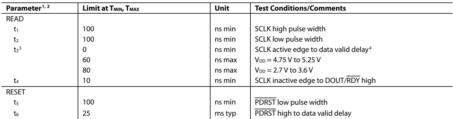
Table 3.
| Parameter1,2 | Limit at $T_{MIN}, T_{MAX}$ | Unit | Test Conditions/Comments |
| READ | |||
| $t_1$ | 100 | ns min | SCLK high pulse width |
| $t_2$ | 100 | ns min | SCLK low pulse width |
| $t_3^3$ | 0 | ns min | SCLK active edge to data valid delay4 |
| 60 | ns max | $V_{DD}= 4.75 V to 5.25 V$ | |
| 80 | ns max | $V_{DD}= 2.7 V to 3.6 V$ | |
| $t_4$ | 10 | ns min | SCLK inactive edge to DOUT/RDY high |
| RESET | |||
| $t_5$ | 100 | ns min | $\overline{PDRST}$ low pulse width |
| $t_6$ | 25 | ms typ | $\overline{PDRST}$ high to data valid delay |
1 Sample tested during initial release to ensure compliance. All input signals are specified with $\mathtt { t } _ { \mathtt { R } } = \mathtt { t } _ { \mathtt { F } } = 5$ ns (10% to 90% of $\mathrm { \Delta V _ { D D } ) }$ and timed from a voltage level of 1.6 V. 2 See Figure 3.
3 These numbers are measured with the load circuit shown in Figure 2 and defined as the time required for the output to cross the $\mathsf { V } _ { \mathsf { O L } } \mathsf { o r } \mathsf { V } _ { \mathsf { O H } }$ limits.
4 SCLK active edge is the falling edge of SCLK.
Timing Diagrams
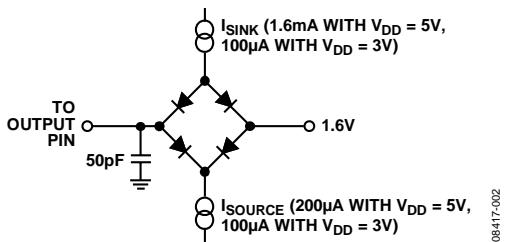
Figure 2. Load Circuit for Timing Characterization
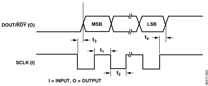
Figure 3. Read Cycle Timing Diagram
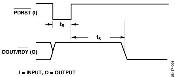
Figure 4. Resetting the AD7171
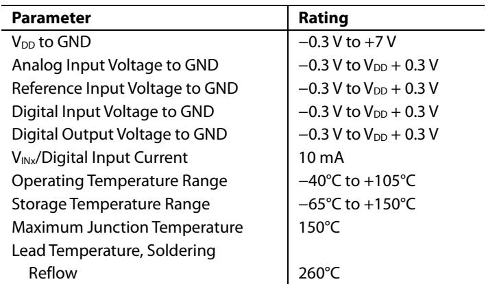
ABSOLUTE MAXIMUM RATINGS
$\mathrm { T } _ { \mathrm { A } } = 2 5 ^ { \circ } \mathrm { C } ,$ , unless otherwise noted.
Table 4.
| Parameter | Rating |
| $V_{DD}$ to GND | -0.3 V to +7 V |
| Analog Input Voltage to GND | -0.3 V to $V_{DD}$ + 0.3 V |
| Reference Input Voltage to GND | -0.3 V to $V_{DD}$ + 0.3 V |
| Digital Input Voltage to GND | -0.3 V to $V_{DD}$ + 0.3 V |
| Digital Output Voltage to GND | -0.3 V to $V_{DD}$ + 0.3 V |
| $V_{INx}/Digital\ Input\ Current$ | 10 mA |
| Operating Temperature Range | -40°C to +105°C |
| Storage Temperature Range | -65°C to +150°C |
| Maximum Junction Temperature | 150°C |
| Lead Temperature, Soldering | |
| Reflow | 260°C |
Stresses at or above those listed under Absolute Maximum Ratings may cause permanent damage to the product. This is a stress rating only; functional operation of the product at these or any other conditions above those indicated in the operational section of this specification is not implied. Operation beyond the maximum operating conditions for extended periods may affect product reliability.
THERMAL RESISTANCE
$\theta _ { \mathrm { J A } }$ is specified for the worst-case conditions, that is, a device soldered in a circuit board for surface-mount packages.
Table 5.
| Package Type | $\theta_{JA}$ | $\theta_{JC}$ | Unit |
| 10-Lead LFCSP | 48.7 | 2.96 | °C/W |
ESD CAUTION

ESD (electrostatic discharge) sensitive device. Charged devices and circuit boards can discharge without detection. Although this product features patented or proprietary protection circuitry, damage may occur on devices subjected to high energy ESD. Therefore, proper ESD precautions should be taken to avoid performance degradation or loss of functionality.
PIN CONFIGURATION AND FUNCTION DESCRIPTIONS
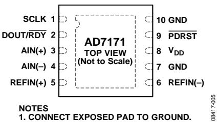
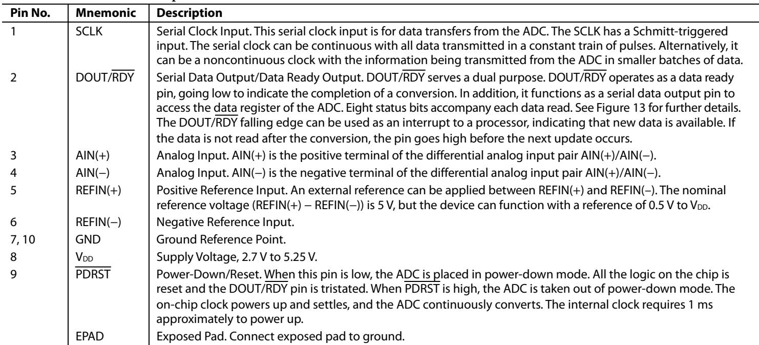
Figure 5. Pin Configuration
Table 6. Pin Function Descriptions
| Pin No. | Mnemonic | Description |
| 1 | SCLK | Serial Clock Input. This serial clock input is for data transfers from the ADC. The SCLK has a Schmitt-triggered input. The serial clock can be continuous with all data transmitted in a constant train of pulses. Alternatively, it can be a noncontinuous clock with the information being transmitted from the ADC in smaller batches of data. |
| 2 | DOUT/RDY | Serial Data Output/Data Ready Output. DOUT/RDY serves a dual purpose. DOUT/RDY operates as a data ready pin, going low to indicate the completion of a conversion. In addition, it functions as a serial data output pin to access the data register of the ADC. Eight status bits accompany each data read. See Figure 13 for further details. The DOUT/RDY falling edge can be used as an interrupt to a processor, indicating that new data is available. If the data is not read after the conversion, the pin goes high before the next update occurs. |
| 3 | AIN(+) | Analog Input. AIN(+) is the positive terminal of the differential analog input pair AIN(+)/AIN(-). |
| 4 | AIN(-) | Analog Input. AIN(-) is the negative terminal of the differential analog input pair AIN(+)/AIN(-). |
| 5 | REFIN(+) | Positive Reference Input. An external reference can be applied between REFIN(+) and REFIN(-). The nominal reference voltage (REFIN(+) - REFIN(-)) is 5 V, but the device can function with a reference of 0.5 V to $V_{DD}$ . |
| 6 | REFIN(-) | Negative Reference Input. |
| 7, 10 | GND | Ground Reference Point. |
| 8 | $V_{DD}$ | Supply Voltage, 2.7 V to 5.25 V. |
| 9 | $\overline{PDRST}$ | Power-Down/Reset. When this pin is low, the ADC is placed in power-down mode. All the logic on the chip is reset and the DOUT/ $\overline{RDY}$ pin is tristated. When $\overline{PDRST}$ is high, the ADC is taken out of power-down mode. The on-chip clock powers up and settles, and the ADC continuously converts. The internal clock requires 1 ms approximately to power up. |
| EPAD | Exposed Pad. Connect exposed pad to ground. |
TYPICAL PERFORMANCE CHARACTERISTICS
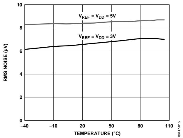
Figure 6. AD7171 RMS Noise vs. Temperature
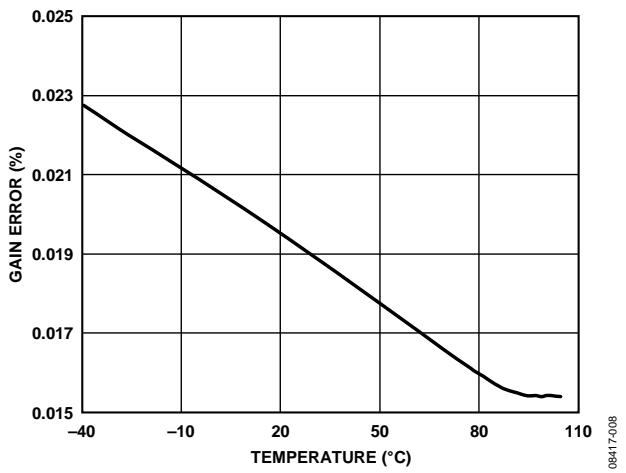
Figure 9. Gain Error vs. Temperature
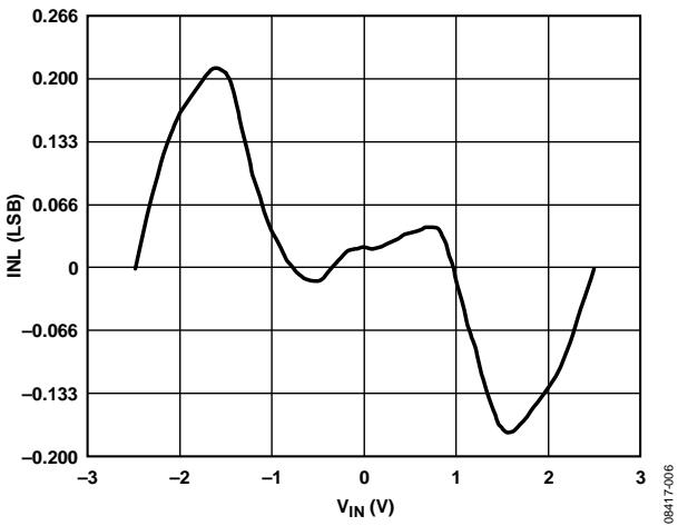
Figure 7. Integral Nonlinearity (VREF = VDD)
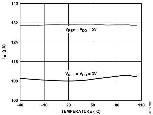
Figure 10. Power Supply Current vs. Temperature
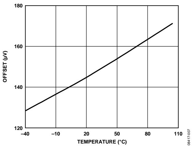
Figure 8. Offset vs. Temperature
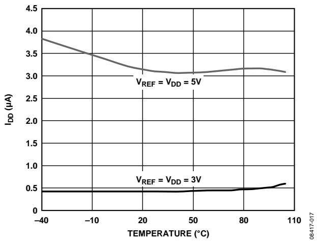
Figure 11. Power-Down Current vs. Temperature
OUTPUT NOISE AND RESOLUTION SPECIFICATIONS
Table 7 shows the rms noise of the AD7171. The numbers given are for a 5 V and a 3 V reference. These numbers are typical and are generated with a differential input voltage of 0 V. The corresponding p-p resolution is also listed along with the effective resolution (ENOB). Note that the effective resolution is calculated using the rms noise, whereas the p-p resolution is based on the p-p noise. The p-p resolution represents the resolution for which there is no code flicker. These numbers are typical.
The effective number of bits (ENOB) is defined as
$$
E N O B = l n (F S R / R M S n o i s e) / l n (2)
$$
The noise-free bits, or p-p resolution, are defined as
$$
\text { Noise - Free Bits } = \ln (\text { FSR / Peak - to - Peak Noise }) / \ln (2)
$$
where FSR is the full-scale range and is equal to 2 × VREF/gain.
Table 7. RMS Noise and Resolution of the AD7171
| $V_{REF} = V_{DD}$ | RMS Noise | P-P Noise | P-P Resolution | ENOB |
| 5 V | 11.5 μV | 76 μV | 16 bits | 16 bits |
| 3 V | 6.9 μV | 45 μV | 16 bits | 16 bits |
ADC CIRCUIT INFORMATION
OVERVIEW
The AD7171 is a low power ADC that incorporates a precision 16-bit Σ-∆ modulator and an on-chip digital filter intended for measuring wide dynamic range, low frequency signals. The device has an internal clock and one differential input. It operates with an output data rate of 125 Hz and has a gain of 1. A 2-wire interface simplifies data retrieval from the AD7171.
FILTER, DATA RATE, AND SETTLING TIME
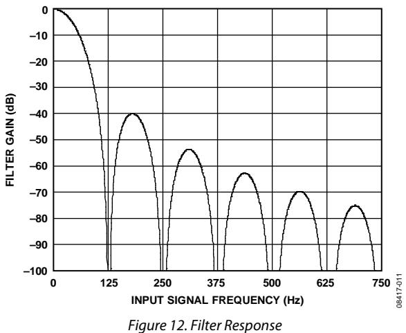
The AD7171 uses a sinc3 filter. The output data rate is set to 125 Hz; thus, valid conversions are available every 1/125 = 8 ms. If a reset occurs, then the user must allow the complete settling time for the first conversion after the reset. The settling time is equal to 24 ms. Subsequent conversions are available at 125 Hz.
When a step change occurs on the analog input, the AD7171 requires several conversion cycles to generate a valid conversion. If the step change occurs synchronous to the conversion period, then the settling time of the AD7171 must be allowed to generate a valid conversion. If the step change occurs asynchronous to the end of a conversion, then an extra conversion must be allowed to generate a valid conversion. The data register is updated with all the conversions but, for an accurate result, the user must allow the required time.
Figure 12 shows the filter response of the filter. The only external filtering required on the analog inputs is a simple RC filter to provide rejection at multiples of the master clock. See Table 8 for suitable external RC combinations.
GAIN
The AD7171 has a gain of 1. The acceptable analog input range is ±VREF. Therefore, with $\mathrm { V } _ { \mathrm { R E F } } = 5 \mathrm { V } ,$ the input range is ±5 V.
POWER-DOWN/RESET (PDRST)
The PDRST pin functions as a power-down pin and a reset pin. When PDRST is taken low, the AD7171 is powered down. The entire ADC is powered down (including the on-chip clock), and the DOUT/RDY pin is tristated. The circuitry and serial interface are also reset. This resets the logic, the digital filter, and the analog modulator. PDRST must be held low for 100 ns minimum to initiate the reset function (see Figure 4).
When PDRST is taken high, the AD7171 is taken out of powerdown mode. When the on-chip clock has powered up (1 ms, typically), the modulator then begins sampling the analog input. The DOUT/RDY pin becomes active, going high until a valid conversion is available. A reset is automatically performed on power-up.
ANALOG INPUT CHANNEL
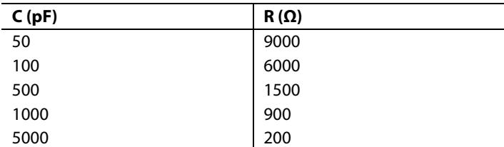
The AD7171 has one differential analog input channel that is connected to the modulator; that is, the input is unbuffered. Note that this unbuffered input path provides a dynamic load to the driving source. Therefore, resistor/capacitor combinations on the input pins can cause dc gain errors, depending on the output impedance of the source that is driving the ADC input. Table 8 shows the allowable external resistance/capacitance values such that no gain error at the 16-bit level is introduced.
Table 8. External RC Combination for No Gain Error
| C (pF) | R (Ω) |
| 50 | 9000 |
| 100 | 6000 |
| 500 | 1500 |
| 1000 | 900 |
| 5000 | 200 |
The absolute input voltage range is restricted to a range between GND − 30 mV and VDD + 30 mV. Care must be taken in setting up the common-mode voltage to avoid exceeding these limits. Otherwise, there is degradation in linearity and noise performance.
BIPOLAR CONFIGURATION
The AD7171 accepts a bipolar input range. A bipolar input range does not imply that the device can tolerate negative voltages with respect to system GND. Signals on the AIN(+) input are referenced to the voltage on the AIN(−) input. For example, if AIN(−) is 2.5 V, the analog input range on the AIN(+) input is 0 V to 5 V when a 2.5 V reference is used.
DATA OUTPUT CODING
The AD7171 uses offset binary coding. Therefore, a negative full-scale voltage results in a code of 000...000, a zero differential input voltage results in a code of 100...000, and a positive fullscale input voltage results in a code of 111...111. The output code for any analog input voltage can be represented as
$$
C o d e = 2 ^ {N - 1} \times ((V _ {\mathrm{INx}} / V _ {R E F}) + 1)
$$
where:
VINx is the analog input voltage.
N = 16 for the AD7171.
REFERENCE
The AD7171 has a fully differential input capability for the channel. The common-mode range for these differential inputs is GND to VDD. The reference input is unbuffered; therefore, excessive RC source impedances introduce gain errors. The reference voltage REFIN (REFIN(+) − REFIN(−)) is VDD nominal, but the AD7171 is functional with reference voltages of 0.5 V to VDD. In applications where the excitation (voltage or current) for the transducer on the analog input also drives the reference voltage for the device, the effect of the low frequency noise in the excitation source is removed because the application is ratiometric. If the AD7171 is used in a nonratiometric application, a low noise reference should be used.
Recommended 2.5 V reference voltage sources for the AD7171 include the ADR381 and ADR391, which are low noise, low power references. Also, note that the reference inputs provide a high impedance, dynamic load. Because the input impedance of each reference input is dynamic, resistor/capacitor combinations on these inputs can cause dc gain errors, depending on the output impedance of the source that is driving the reference inputs.
Reference voltage sources such as those recommended above (the ADR391, for example) typically have low output impedances and are, therefore, tolerant to decoupling capacitors on REFIN(+) without introducing gain errors in the system. Deriving the reference input voltage across an external resistor means that the reference input sees a significant external source impedance. External decoupling on the REFIN(±) pins is not recommended in this type of circuit configuration.
DIGITAL INTERFACE
The serial interface of the AD7171 consists of two signals: SCLK and DOUT/RDY SCLK is the serial clock input for the device, and data transfers occur with respect to the SCLK signal. The DOUT/RDY pin is dual purpose: it functions as a data ready pin and as a data out pin. DOUT/RDY goes low when a new data-word is available in the output register. A 24-bit word is placed on the DOUT/RDY pin when sufficient SCLK pulses are applied. This consists of a 16-bit conversion result followed by eight status bits. Table 9 shows the functions of the status bits.
RDY: Ready bit. This bit is set low to indicate that a conversion is available.
0: This bit is set to 0.
ERR: This bit is set to 1 if an error occurred during the conversion. An error occurs when the analog input is outside range.
ID1, ID0: ID bits. These bits indicate the ID number for the AD7171. Bit ID1 is set to 0 and Bit ID0 is set to 1 for the AD7171.
PAT2, PAT1, PAT0: Status pattern bits. These bits are set to 101 by default. When the user reads the data from the AD7171, a pattern check can be performed. If the PAT2 to PAT0 bits are different from their default values, the serial transfer from the ADC was not performed correctly.
Table 9. Status Bits
| RDY | 0 | ERR | ID1 | ID0 | PAT2 | PAT1 | PATO |
DOUT/RDY is reset high when the conversion is read. If the conversion is not read, DOUT/RDY goes high prior to the data register update to indicate when not to read from the device. This ensures that a read operation is not attempted while the register is being updated. Each conversion can be read only once. The data register is updated for every conversion. Therefore, when a conversion is complete, the serial interface resets, and the new conversion is placed in the data register. Therefore, the user must ensure that the complete word is read before the next conversion is complete.
When PDRST is low, the DOUT/RDY pin is tristated. When PDRST is taken high, the internal clock requires 1 ms, approximately, to power up. Following this, the ADC continuously converts. The first conversion requires the complete settling time (see Figure 4). DOUT/RDY goes high when PDRST is taken high and returns low only when a conversion is available. The ADC then converts continuously, subsequent conversions being available at 125 Hz. Figure 3 shows the timing for a read operation from the AD7171.
GROUNDING AND LAYOUT
Because the analog input and reference input of the ADC are differential, most of the voltages in the analog modulator are common-mode voltages. The excellent common-mode rejection of the device removes common-mode noise on these inputs. The digital filter provides rejection of broadband noise on the power supply, except at integer multiples of the modulator sampling frequency. The digital filter also removes noise from the analog and reference inputs provided that these noise sources do not saturate the analog modulator. As a result, the AD7171 is more immune to noise interference than conventional high resolution converters. However, because the noise levels from the AD7171 are so low, care must be taken with regard to grounding and layout.
The printed circuit board that houses the AD7171 should be designed such that the analog and digital sections are separated and confined to certain areas of the board. A minimum etch technique is generally best for ground planes because it gives the best shielding.
It is recommended that the GND pin of the AD7171 be tied to the analog ground (AGND) plane of the system. In any layout, it is important that the user pay attention to the flow of currents in the system, and ensure that the return paths for all currents are as close as possible to the paths the currents took to reach their destinations. Avoid forcing digital currents to flow through the AGND sections of the layout.
The ground plane of the AD7171 should be allowed to run under the AD7171 to prevent noise coupling. The power supply lines to the AD7171 should use as wide a trace as possible to provide low impedance paths and reduce the effects of glitches on the power supply line. Fast switching signals such as clocks should be shielded with digital ground to avoid radiating noise to other sections of the board, and clock signals should never be run near the analog inputs. Avoid crossover of digital and analog signals. Traces on opposite sides of the board should run at right angles to each other. This reduces the effects of feedthrough through the board. A microstrip technique is by far the best, but it is not always possible with a double-sided board. In this technique, the component side of the board is dedicated to ground planes, while signals are placed on the solder side.
Good decoupling is important when using high resolution ADCs. VDD should be decoupled with 10 µF tantalum capacitors in parallel with 0.1 µF capacitors to GND, with the analog ground to digital ground (DGND) connection of the system being close to the AD7171. To achieve the best results from these decoupling components, they should be placed as close as possible to the device, ideally right up against the device. All logic chips should be decoupled with 0.1 µF ceramic capacitors to DGND.
APPLICATIONS INFORMATION
The AD7171 provides a low cost, high resolution analog-to-digital function. Because the analog-to-digital function is provided by a Σ-Δ architecture, the device is more immune to noisy environments, making it ideal for use in sensor measurement and industrial and process-control applications.
TEMPERATURE SYSTEM
Figure 13 shows the AD7171 used in a temperature measurement system. The thermistor is connected in series with a precision resistor, RREF, the precision resistor being used to generate the reference voltage. The value of RREF is equal to the maximum resistance produced by the thermistor. The complete dynamic range of the ADC is then used, resulting in optimum performance. See Table 8 for suitable external RC combinations.
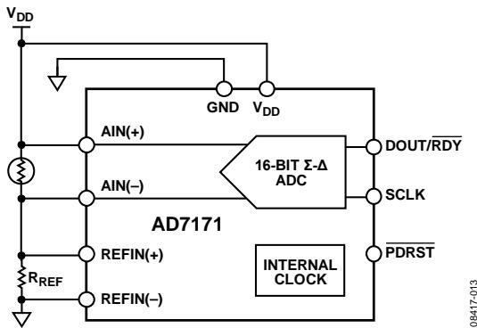
Figure 13. Temperature System Using the AD7171
SIGNAL CONDITIONING CIRCUIT
Figure 14 shows the AD7171 used in a signal conditioning circuit for a single-ended analog input. In a low side shunt current monitor, a low resistance shunt resistor converts the current to voltage. The resulting voltage is amplified and applied to the AD7171.
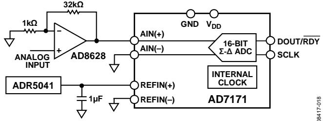
Figure 14. Signal Conditioning Circuit
(CP-10-9)
OUTLINE DIMENSIONS
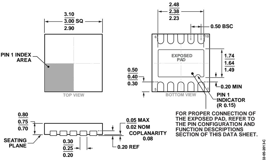
Figure 15. 10-Lead Lead Frame Chip Scale Package [LFCSP_WD]
3 mm × 3 mm Body, Very Very Thin, Dual Lead
Dimensions shown in millimeters
ORDERING GUIDE
| Model1 | Temperature Range | Package Description | Package Option | Branding |
| AD7171BCPZ-REEL7 | -40°C to +105°C | 10-Lead Lead Frame Chip Scale Package [LFCSP_WD] | CP-10-9 | C6G |
| AD7171BCPZ-500RL7 | -40°C to +105°C | 10-Lead Lead Frame Chip Scale Package [LFCSP_WD] | CP-10-9 | C6G |
| EVAL-AD7171EBZ | Evaluation Board |
1 Z = RoHS Compliant Part.
NOTES
NOTES
Figures and diagrams from the PDF
Preview the extracted datasheet assets and open any image in a separate tab for closer inspection.









Use this datasheet from any agent
Send the page, markdown, chunks, or search endpoint to ChatGPT, Claude, embedr-app, or your own tooling.