
DPO2036
4-channel USB Type-C CC/SBU over-voltage protection device with dead-battery support and active-low fault output.
Description
The DPO2036 provides 4 channels of over-voltage protection over the CC1/2 & SBU1/2 pins which are connected to the USB Type-C® connector. The 4 channels are divided into two pairs, one pair of channels protect the CC1 and CC2 pins from being shorted to the VBUS, one pair of channels protect the SBU1 and SBU2 pins from being shorted to the VBUS. Whenever the voltage threshold set for any of the two pairs of channels is reached, the exception condition becomes valid and the low-active flag FAULTB is subsequently asserted.
This device is designed to draw its operating voltage primarily from the system power, VVSYS, which is either the always-ON 3.3V/5V existed within the system or the 1-cell battery inside the mobile system. Under the circumstance when the battery inside a mobile system is fully depleted, DPO2036 can obtain power from the external peripheral system connected to the USB Type-C connector. The DPO2036 supports the dead battery mode by having both of the CC1C and CC2C pins tied to the pull-down resistor R (resistor value per the USB Type-C Specification) embedded in the device.
The DPO2036 is housed in the low-profile and space-saving U-QFN2020-12 (Type B) package which is manufactured with environmental-friendly material.
Pin Assignments
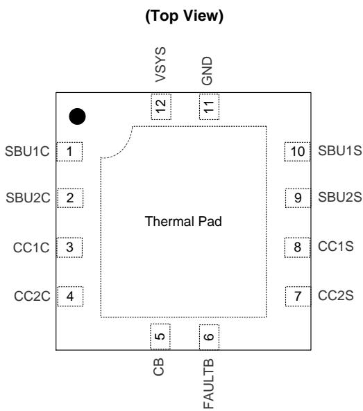
U-QFN2020-12 (Type B)
Features
Operating Voltage Range: 2.7V to 5.5V
4-Channel Over-Voltage Protection with Auto-Recovery
RDS(ON) of OVP MOSFET for CC-Pin Protection: 350mΩ Typical
RDS(ON) of OVP MOSFET for SBU-Pin Protection: 5Ω Typical
CIN of OVP MOSFET for CC-Pin Protection: 50pF
CIN of OVP MOSFET for SBU-Pin Protection: 5pF
Dead Battery Support for CC Lines
Built-In Over-Temperature Protection
IEC61000-4-2 ESD Protection on CC1C, CC2C, SBU1C, SBU2C
Totally Lead-Free & Fully RoHS Compliant (Notes 1 & 2)
Halogen and Antimony Free. “Green” Device (Note 3)
For automotive applications requiring specific change control (i.e. parts qualified to AEC-Q100/101/200, PPAP capable, and manufactured in IATF 16949 certified facilities), please contact us or your local Diodes representative. https://www.diodes.com/quality/product-definitions/
Applications
Notebook/Desktop/AIO PCs, Tablets, Mobile Phones
VR/AR Headsets
Docking Stations, Universal & Multimedia Hubs
FPTVs, PC Monitors
Set-Top-Boxes, Residential Gateways, Storage Devices
Universal AC/DC Chargers/Adapters
Notes: 1. No purposely added lead. Fully EU Directive 2002/95/EC (RoHS), 2011/65/EU (RoHS 2) & 2015/863/EU (RoHS 3) compliant.
See https://www.diodes.com/quality/lead-free/ for more information about Diodes Incorporated’s definitions of Halogen- and Antimony-free, "Green" and Lead-free.
Halogen- and Antimony-free "Green” products are defined as those which contain <900ppm bromine, <900ppm chlorine (<1500ppm total Br + Cl) and <1000ppm antimony compounds.
Typical Application Circuit
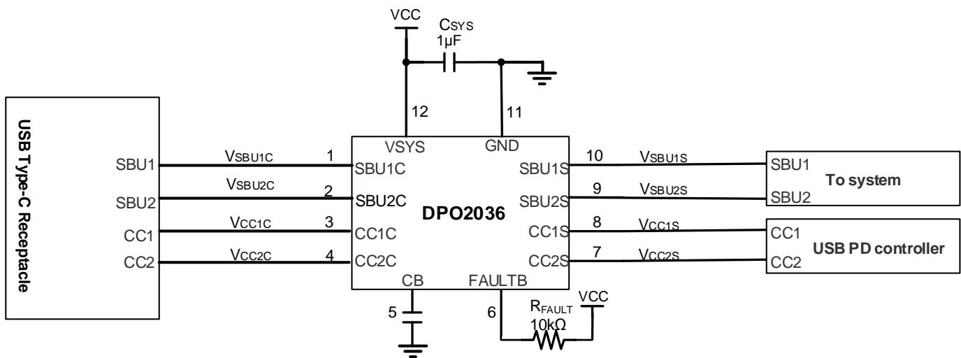
Figure 1. Typical Application Circuit
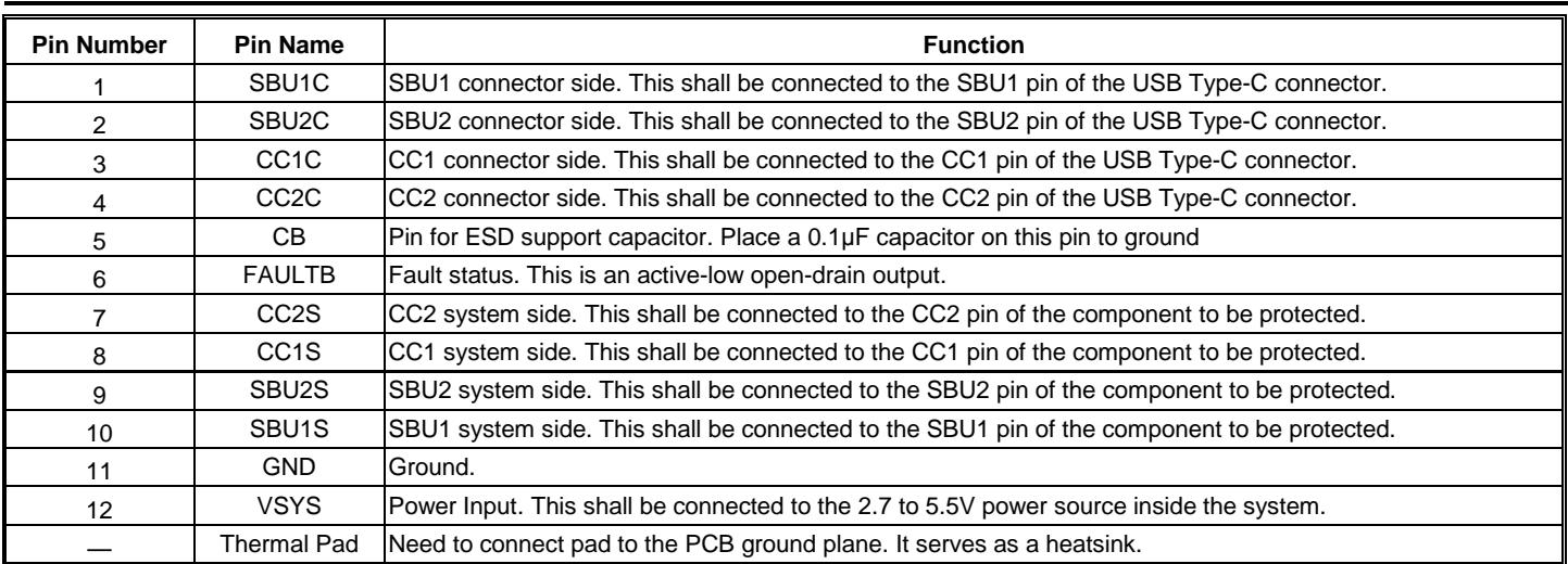
| Pin Number | Pin Name | Function |
| 1 | SBU1C | SBU1 connector side. This shall be connected to the SBU1 pin of the USB Type-C connector. |
| 2 | SBU2C | SBU2 connector side. This shall be connected to the SBU2 pin of the USB Type-C connector. |
| 3 | CC1C | CC1 connector side. This shall be connected to the CC1 pin of the USB Type-C connector. |
| 4 | CC2C | CC2 connector side. This shall be connected to the CC2 pin of the USB Type-C connector. |
| 5 | CB | Pin for ESD support capacitor. Place a 0.1μF capacitor on this pin to ground |
| 6 | FAULTB | Fault status. This is an active-low open-drain output. |
| 7 | CC2S | CC2 system side. This shall be connected to the CC2 pin of the component to be protected. |
| 8 | CC1S | CC1 system side. This shall be connected to the CC1 pin of the component to be protected. |
| 9 | SBU2S | SBU2 system side. This shall be connected to the SBU2 pin of the component to be protected. |
| 10 | SBU1S | SBU1 system side. This shall be connected to the SBU1 pin of the component to be protected. |
| 11 | GND | Ground. |
| 12 | VSYS | Power Input. This shall be connected to the 2.7 to 5.5V power source inside the system. |
| — | Thermal Pad | Need to connect pad to the PCB ground plane. It serves as a heatsink. |
Functional Block Diagram
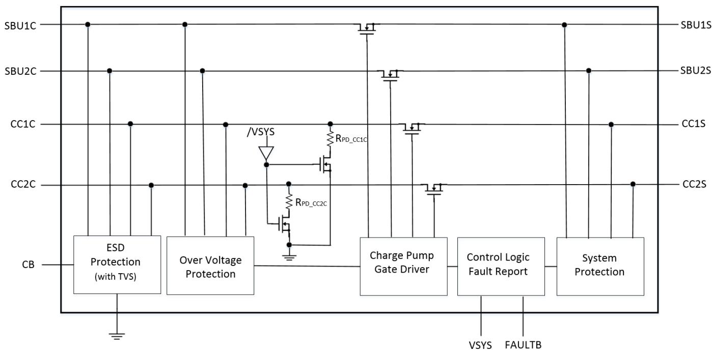
Figure 2. Internal Functional Blocks
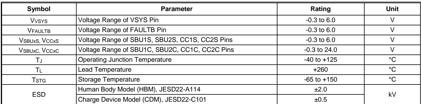
Absolute Maximum Ratings (@ ${ \sf T } _ { \sf A } = + 2 5 ^ { \circ } { \sf C } ,$ , unless otherwise specified.) (Note 4)
| Symbol | Parameter | Rating | Unit |
| $V_{VSYS}$ | Voltage Range of VSYS Pin | -0.3 to 6.0 | V |
| $V_{FAULTB}$ | Voltage Range of FAULTB Pin | -0.3 to 6.0 | V |
| $V_{SBUxS}, V_{CCxS}$ | Voltage Range of SBU1S, SBU2S, CC1S, CC2S Pins | -0.3 to 6.0 | V |
| $V_{SBUxC}, V_{CCxC}$ | Voltage Range of SBU1C, SBU2C, CC1C, CC2C Pins | -0.3 to 24.0 | V |
| $T_J$ | Operating Junction Temperature | -40 to +125 | °C |
| $T_L$ | Lead Temperature | +260 | °C |
| $T_{STG}$ | Storage Temperature | -65 to +150 | °C |
| ESD | Human Body Model (HBM), JESD22-A114 | ±2.0 | kV |
| Charge Device Model (CDM), JESD22-C101 | ±0.5 |
Note: 4. These are stress ratings only. Operation outside the absolute maximum ratings can cause device failure Operation at the absolute maximum rating for extended periods can reduce device reliability.
Package Thermal Data (@ ${ \mathsf { T } } _ { \mathsf { A } } = + 2 5 ^ { \circ } { \mathsf { C } } ,$ unless otherwise specified.) (Note 5)
| Symbol | Parameter | Rating | Unit |
| $P_D$ | Power Dissipation | 1.3 | W |
| $R_{\theta JA}$ | Thermal Resistance, Junction-to-Ambient | 96 | °C/W |
| $R_{\theta JC}$ | Thermal Resistance, Junction-to-Case | 26 | °C/W |
Note: 5. Device mounted on FR-4 substrate PC board, 2oz copper, with 1” 1” copper pad layout.
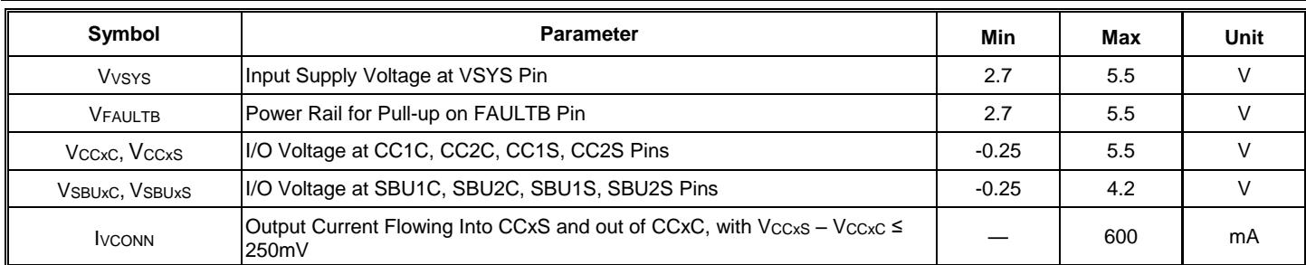
Recommended Operating Conditions (@ ${ \sf T } _ { \sf A } = + 2 5 ^ { \circ } { \sf C } ,$ unless otherwise specified.)
| Symbol | Parameter | Min | Max | Unit |
| $V_{Vsys}$ | Input Supply Voltage at VSYS Pin | 2.7 | 5.5 | V |
| $V_{FAULTB}$ | Power Rail for Pull-up on FAULTB Pin | 2.7 | 5.5 | V |
| $V_{CCxC}, V_{CCxS}$ | I/O Voltage at CC1C, CC2C, CC1S, CC2S Pins | -0.25 | 5.5 | V |
| $V_{SBUXC}, V_{SBUXS}$ | I/O Voltage at SBU1C, SBU2C, SBU1S, SBU2S Pins | -0.25 | 4.2 | V |
| $I_{VCONN}$ | Output Current Flowing Into CCxS and out of CCxC, with $V_{CCxS} - V_{CCxC} \leq 250mV$ | — | 600 | mA |
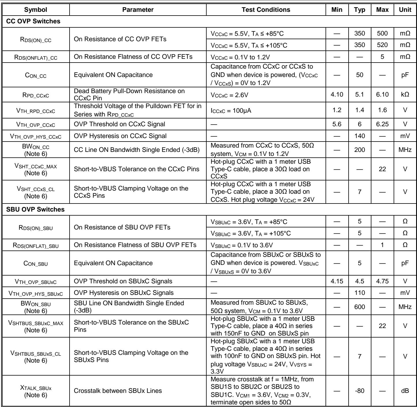
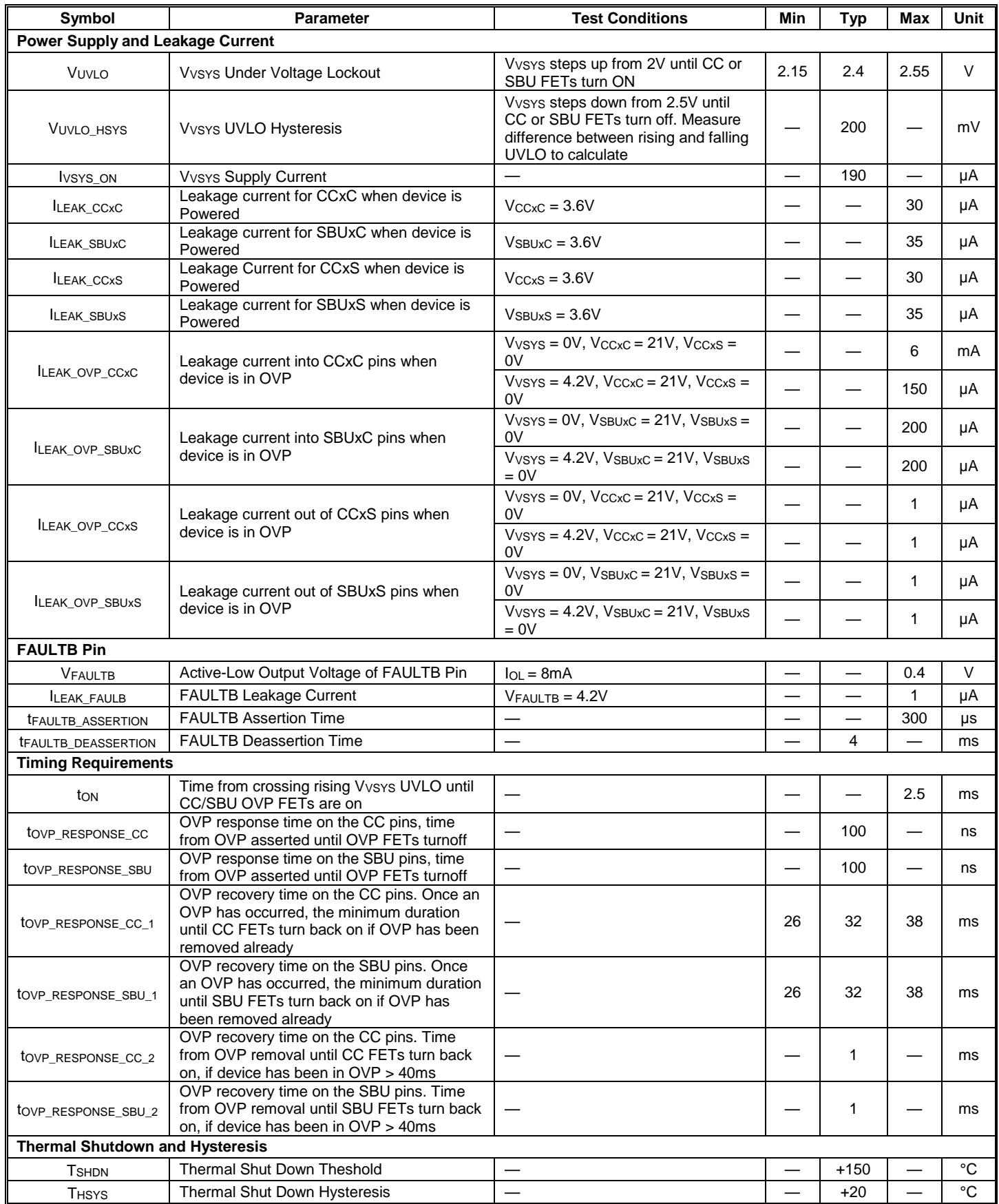
Electrical Characteristics (@ TA = +25°C, VVSYS = 4.2V, unless otherwise specified.)
| Symbol | Parameter | Test Conditions | Min | Typ | Max | Unit |
| CC OVP Switches | ||||||
| $R_{DS(ON)_CC}$ | On Resistance of CC OVP FETs | $V_{CCxC}=5.5V, T_A\leq+85°C$ | — | 350 | 500 | mΩ |
| $V_{CCxC}=5.5V, T_A\leq+105°C$ | — | 350 | 520 | mΩ | ||
| $R_{DS(ONFLAT)_CC}$ | On Resistance Flatness of CC OVP FETs | $V_{CCxC}=0.1V to 1.2V$ | — | — | 5 | mΩ |
| $C_{ON\_CC}$ | Equivalent ON Capacitance | Capacitance from CCxC or CCxS to GND when device is powered, ( $V_{CCxC}/V_{CCxS}$ ) = 0V to 1.2V | — | 50 | — | pF |
| $R_{PD\_CCxC}$ | Dead Battery Pull-Down Resistance on CCxC Pin | $V_{CCxC}=2.6V$ | 4.10 | 5.1 | 6.10 | kΩ |
| $V_{TH\_RPD\_CCxC}$ | Threshold Voltage of the Pulldown FET for in Series with $R_{PD\_CCxC}$ | $I_{CCxC}=100μA$ | 1.2 | 1.4 | 1.6 | V |
| $V_{TH\_OVP\_CCxC}$ | OVP Threshold on CCxC Signal | — | 5.6 | 6 | 6.25 | V |
| $V_{TH\_OVP\_HYS\_CCxC}$ | OVP Hysteresis on CCxC Signal | — | — | 140 | — | mV |
| $B_{WON\_CC}$ (Note 6) | CC Line ON Bandwidth Single Ended (-3dB) | Measured from CCxC to CCxS, 50Ω system, $V_{CM}=0.1V to 1.2V$ | — | 200 | — | MHz |
| $V_{SHT\_CCxC\_MAX}$ (Note 6) | Short-to-VBUS Tolerance on the CCxC Pins | Hot-plug CCxC with a 1 meter USB Type-C cable, place a 30Ω load on CCxS | — | — | 22 | V |
| $V_{SHT\_CCxS\_CL}$ (Note 6) | Short-to-VBUS Clamping Voltage on the CCxC Pins | Hot-plug CCxC with a 1 meter USB Type-C cable, place a 30Ω load on CCxC. Hot plug voltage $V_{CCxC}=24V$ | — | 7 | — | V |
| SBU OVP Switches | ||||||
| $R_{DS(ON)_SBU}$ | On Resistance of SBU OVP FETs | $V_{SBUxC}=3.6V, T_A=+85°C$ | — | 5 | — | Ω |
| $V_{SBUxC}=3.6V, T_A=+105°C$ | — | 5 | — | Ω | ||
| $R_{DS(ONFLAT)_SBU}$ | On Resistance Flatness of SBU OVP FETs | $V_{SBUxC}=0.1V to 3.6V$ | — | — | 1 | Ω |
| $C_{ON\_SBU}$ | Equivalent ON Capacitance | Capacitance from SBUxC or SBUxS to GND when device is powered. $V_{SBUxC}/V_{SBUxS}=0V to 3.6V$ | — | 5 | — | pF |
| $V_{TH\_OVP\_SBUxC}$ | OVP Threshold on SBUxC Signals | — | 4.15 | 4.5 | 4.75 | V |
| $V_{TH\_OVP\_HYS\_SBUxC}$ | OVP Hysteresis on SBUxC Signals | — | — | 110 | — | mV |
| $B_{WON\_SBU}$ (Note 6) | SBU Line ON Bandwidth Single Ended (-3dB) | Measured from SBUxC to SBUxS, 50Ω system, $V_{CM}=0.1V to 3.6V$ | — | 600 | — | MHz |
| $V_{SHTBUS\_SBUxC\_MAX}$ (Note 6) | Short-to-VBUS Tolerance on the SBUxC Pins | Hot-plug SBUxC with a 1 meter USB Type-C cable, place a 40Ω in series with 150nF to GND on SBUxS pin | — | — | 22 | V |
| $V_{SHTBUS\_SBUxS\_CL}$ (Note 6) | Short-to-VBUS Clamping Voltage on the SBUxS Pins | Hot-plug SBUxC with a 1 meter USB Type-C cable, place a 40Ω in series with 100nF to GND on SBUxS pin. Hot plug voltage $V_{SBUxC}=24V, V_{VSYS}=3.3V$ | — | 7 | — | V |
| $X_{TALK\_SBUx}$ (Note 6) | Crosstalk between SBUx Lines | Measure crosstalk at f = 1MHz, from SBU1S to SBU2C or SBU2S to SBU1C. $V_{CM1}=3.6V, V_{CM2}=0.3V$ , terminate open sides to 50Ω | — | -80 | — | dB |
| Power Supply and Leakage Current | ||||||
| $V_{UVLO}$ | $V_{VSYS}$ Under Voltage Lockout | $V_{VSYS}$ steps up from 2V until CC or SBU FETs turn ON | 2.15 | 2.4 | 2.55 | V |
| $V_{UVLO\_HSYS}$ | $V_{VSYS}$ UVLO Hysteresis | $V_{VSYS}$ steps down from 2.5V until CC or SBU FETs turn off. Measure difference between rising and falling UVLO to calculate | — | 200 | — | mV |
| $I_{VSYS\_ON}$ | $V_{VSYS}$ Supply Current | — | — | 190 | — | μA |
| $I_{LEAK\_CCxC}$ | Leakage current for CCxC when device is Powered | $V_{CCxC}=3.6V$ | — | — | 30 | μA |
| $I_{LEAK\_SBUxC}$ | Leakage current for SBUxC when device is Powered | $V_{SBUxC}=3.6V$ | — | — | 35 | μA |
| $I_{LEAK\_CCxS}$ | Leakage Current for CCxS when device is Powered | $V_{CCxS}=3.6V$ | — | — | 30 | μA |
| $I_{LEAK\_SBUxS}$ | Leakage current for SBUxS when device is Powered | $V_{SBUxS}=3.6V$ | — | — | 35 | μA |
| $I_{LEAK\_OVP\_CCxC}$ | Leakage current into CCxC pins when device is in OVP | $V_{VSYS}=0V, V_{CCxC}=21V, V_{CCxS}=0V$ | — | — | 6 | mA |
| $V_{VSYS}=4.2V, V_{CCxC}=21V, V_{CCxS}=0V$ | — | — | 150 | μA | ||
| $I_{LEAK\_OVP\_SBUxC}$ | Leakage current into SBUxC pins when device is in OVP | $V_{VSYS}=0V, V_{SBUxC}=21V, V_{SBUxS}=0V$ | — | — | 200 | μA |
| $V_{VSYS}=4.2V, V_{SBUxC}=21V, V_{SBUxS}=0V$ | — | — | 200 | μA | ||
| $I_{LEAK\_OVP\_CCxS}$ | Leakage current out of CCxS pins when device is in OVP | $V_{VSYS}=0V, V_{CCxC}=21V, V_{CCxS}=0V$ | — | — | 1 | μA |
| $V_{VSYS}=4.2V, V_{CCxC}=21V, V_{CCxS}=0V$ | — | — | 1 | μA | ||
| $I_{LEAK\_OVP\_SBUxS}$ | Leakage current out of SBUxS pins when device is in OVP | $V_{VSYS}=0V, V_{SBUxC}=21V, V_{SBUxS}=0V$ | — | — | 1 | μA |
| $V_{VSYS}=4.2V, V_{SBUxC}=21V, V_{SBUxS}=0V$ | — | — | 1 | μA | ||
| FAULTB Pin | ||||||
| $V_{FAULTB}$ | Active-Low Output Voltage of FAULTB Pin | $I_{OL}=8mA$ | — | — | 0.4 | V |
| $I_{LEAK\_FAULTB}$ | FAULTB Leakage Current | $V_{FAULTB}=4.2V$ | — | — | 1 | μA |
| $t_{FAULTB\_ASSERTION}$ | FAULTB Assertion Time | — | — | — | 300 | μs |
| $t_{FAULTB\_DEASSERTION}$ | FAULTB Deassertion Time | — | — | 4 | — | ms |
| Timing Requirements | ||||||
| $t_{ON}$ | Time from crossing rising $V_{VSYS}$ UVLO until CC/SBU OVP FETs are on | — | — | — | 2.5 | ms |
| $t_{OVP\_RESPONSE\_CC}$ | OVP response time on the CC pins, time from OVP asserted until OVP FETs turnoff | — | — | 100 | — | ns |
| $t_{OVP\_RESPONSE\_SBU}$ | OVP response time on the SBU pins, time from OVP asserted until OVP FETs turnoff | — | — | 100 | — | ns |
| $t_{OVP\_RESPONSE\_CC\_1}$ | OVP recovery time on the CC pins. Once an OVP has occurred, the minimum duration until CC FETs turn back on if OVP has been removed already | — | 26 | 32 | 38 | ms |
| $t_{OVP\_RESPONSE\_SBU\_1}$ | OVP recovery time on the SBU pins. Once an OVP has occurred, the minimum duration until SBU FETs turn back on if OVP has been removed already | — | 26 | 32 | 38 | ms |
| $t_{OVP\_RESPONSE\_CC\_2}$ | OVP recovery time on the CC pins. Time from OVP removal until CC FETs turn back on, if device has been in OVP >40ms | — | — | 1 | — | ms |
| $t_{OVP\_RESPONSE\_SBU\_2}$ | OVP recovery time on the SBU pins. Time from OVP removal until SBU FETs turn back on, if device has been in OVP >40ms | — | — | 1 | — | ms |
| Thermal Shutdown and Hysteresis | ||||||
| $T_{SHDN}$ | Thermal Shut Down Theshold | — | — | +150 | — | °C |
| $T_{HSYS}$ | Thermal Shut Down Hysteresis | — | — | +20 | — | °C |
Performance Characteristics (@ ${ \sf T } _ { \sf A } = + 2 5 ^ { \circ } { \sf C } ,$ unless otherwise specified.)
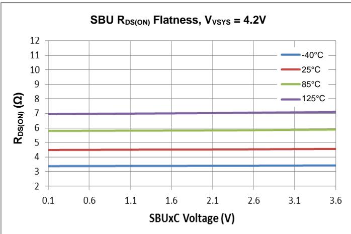
Figure 3. SBU $\overline { { \mathsf { R } _ { \mathsf { D S ( O N ) } } } }$ Flatness
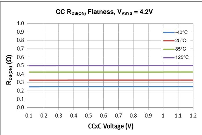
Figure 4. CC $\overline { r } \cos ( 0 N )$ Flatness
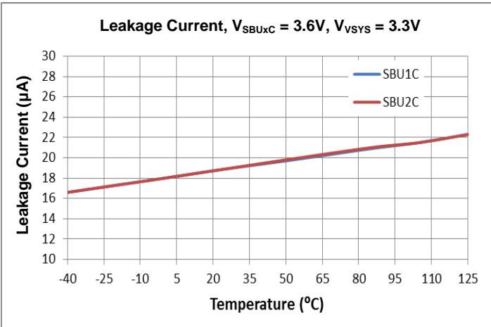
Figure 5. SBUxC Leakage Current vs. Temperature
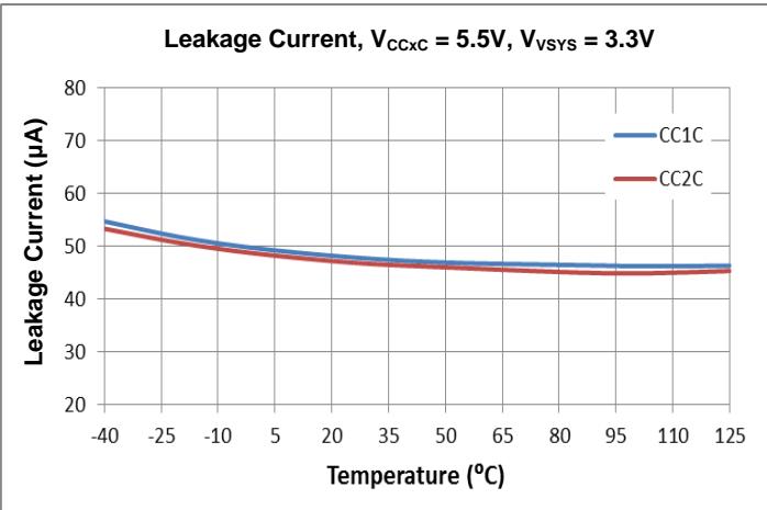
Figure 6. CCxC Leakage Current vs. Temperature
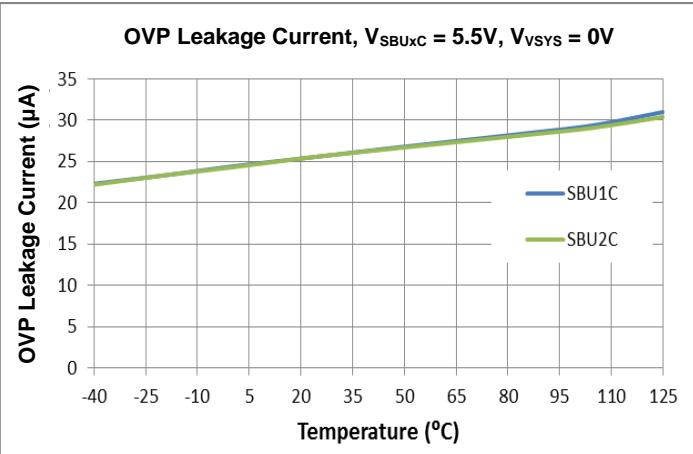
Figure 7. SBUxC 5.5V OVP Leakage Current vs. Temperature
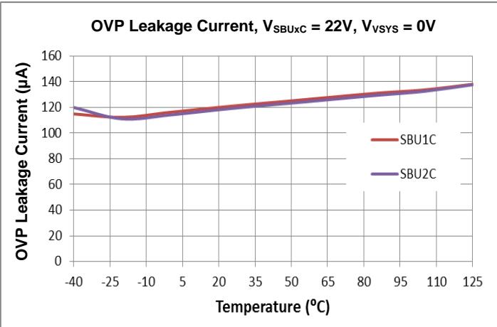
Figure 8. SBUxC 22V OVP Leakage Current vs. Temperature
Performance Characteristics (@ ${ \sf T } _ { \sf A } = + 2 5 ^ { \circ } { \sf C } ,$ unless otherwise specified.) (continued)
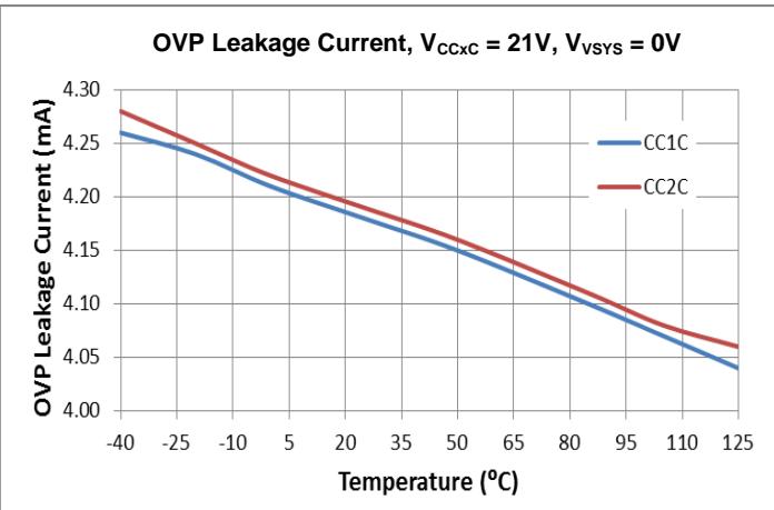
Figure 9. CCxC OVP Leakage Current vs. Temperature
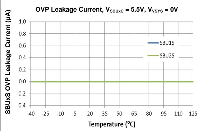
Figure 10. SBUxS OVP Leakage Current vs. Temperature
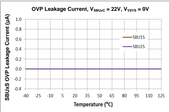
Figure 11. SBUxS OVP Leakage Current vs. Temperature
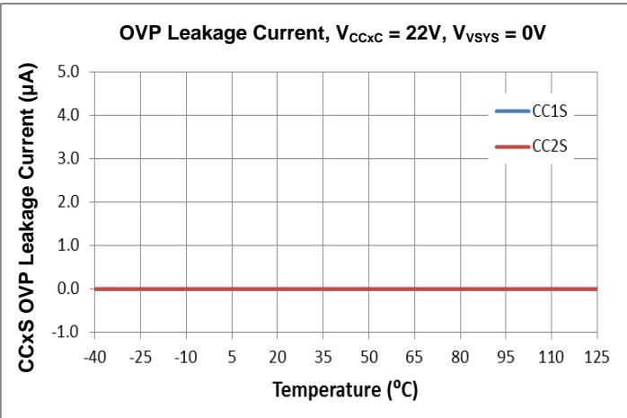
Figure 12. CCxS OVP Leakage Current vs. Temperature
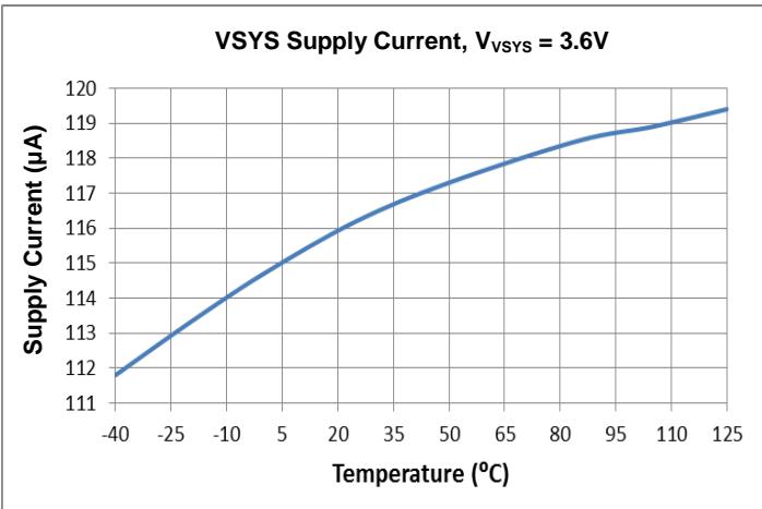
Figure 13. VSYS Supply Current vs Temperature
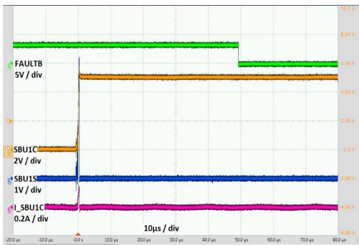
Figure 14. SBU1C Short to 5V VBUS
Performance Characteristics (@ ${ \sf T } _ { \sf A } = + 2 5 ^ { \circ } { \sf C } ,$ unless otherwise specified.) (continued)
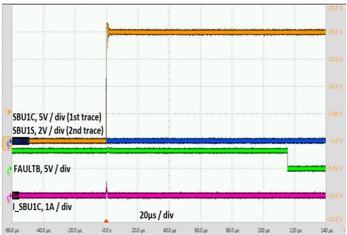
Figure 15. SBU1C Short to 20V VBUS
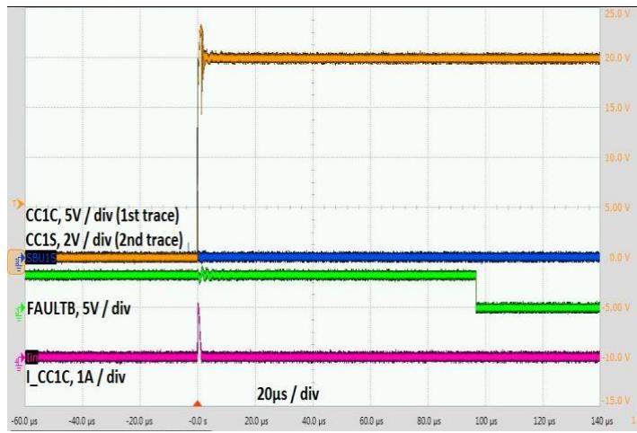
Figure 16. CC1C Short to 20V VBUS
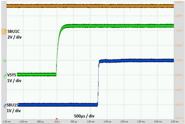
Figure 17. SBU MOSFET Turn-On Time
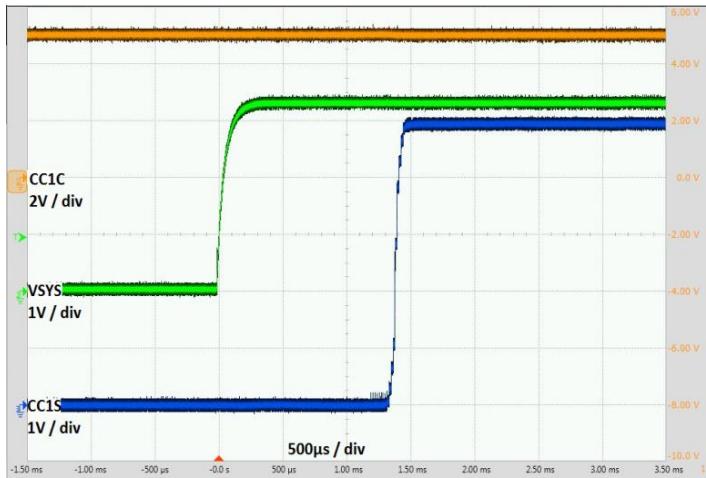
Figure 18. CC MOSFET Turn-On Time
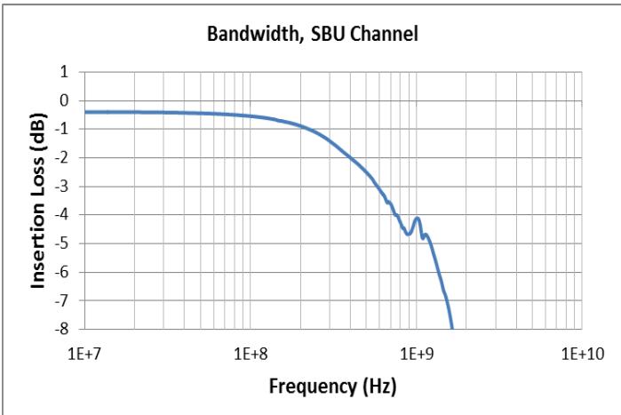
Figure 19. SBU Channel Bandwidth
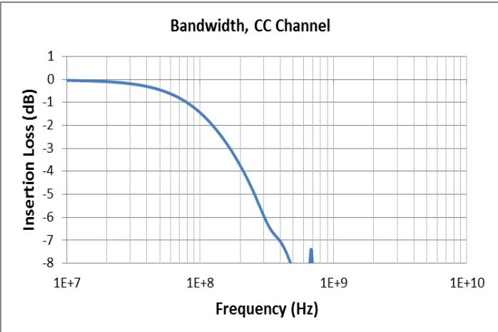
Figure 20. CC Channel Bandwidth
Performance Characteristics (@ ${ \sf T } _ { \sf A } = + 2 5 ^ { \circ } { \sf C } ,$ unless otherwise specified.) (continued)
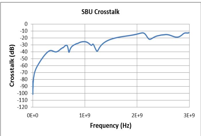
Figure 21. SBU Crosstalk
Application Information
General Description
The DPO2036 is a USB port protection device designed to work with USB Type-C connector, cable and USB PD to form a system that enables signal management and power delivery in a compact package. It provides short to VBUS protection for the CC and SBU pins over the USB Type-C connector, and supports the dead battery mode of operation in an end system / product where the embedded battery is fully depleted.
Short to VBUS Protection
The DPO2036 is a 4-channel uni-directional power switch with over-voltage protection. This is used to prevent the components inside a system which adopts the USB Type-C connector from being damaged by unexpected hazard. On the USB Type-C connector, the CC and SBU pins are located in the close proximity of the VBUS pin. If ever the CC and/or the SBU lines are short to the VBUS line either at the USB-C connector or at the cable end, the components (mostly ICs manufactured on the various sub-micron process nodes) behind the USB Type-C connector can easily be damaged by the resulting EOS. The damage, if occurred, is likely non-recoverable especially given that the voltage level on the VBUS line can go up to 20V or slightly higher. The DPO2036 integrates four series over-voltage FETs to protect the system side CC and SBU lines. When either line on the Type-C connector side CC1C, CC2C, SBU1C or SBU2C is shorted to VBUS line, the DPO2036 will turn off the over-voltage FETs in less than 100ns window to isolate the system side CC and SBU lines from the over-voltage connector side. When shorted to VBUS line is detected, the open-drain FAULTB will output low to indicate a fault condition.
Dead Battery Charging and Power Delivery
In a battery-powered system, the pull-down resistors embedded inside DPO2036 are turned ON and connected to the CC1C/CC2C pins whenever the battery is depleted. Subsequently, the battery-powered system shall receive power through the USB Type-C connector from the external device connected. As soon as the embedded battery is sufficiently recharged to power the system and DPO2036, the pull-down resistors shall be disconnected from the CC1C/CC2C pins.
Signal Operation Range
Table 1 and Table 2 show the signal operation range and output status:
| 0V to UVLO (Invalid) | 0V to 5.85V | OFF: Dead Battery $R_{PD}$ Inserted |
| 5.85V to 20V | OFF: Dead Battery $R_{PD}$ Inserted | |
| 2.7V to 5.5V (Valid) | 0V to 5.85V | ON |
| 5.85V to 20V | OFF: FAULTB Asserted (OVP detected) |
Table 1. Signal Operation Range for CCx
| 0V to UVLO (Invalid) | 0V to 4.35V | OFF |
| 4.35V to 20V | OFF | |
| 2.7V to 5.5V (Valid) | 0V to 4.35V | ON |
| 4.35V to 20V | OFF: FAULTB Asserted (OVP detected) |
Table 2. Signal Operation Range for SBUx
Ordering Information (Note 7)
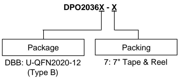
| Part Number | Marking ID | Reel Size (inches) | Tape Width (mm) | 7” Tape and Reel | |
| Quantity | Part Number Suffix | ||||
| DPO2036DBB-7 | PO36 | 7 | 8 | 3,000/Tape & Reel | -7 |
Note: 7. For packaging details, go to our website at https://www.diodes.com/design/support/packaging/diodes-packaging/.
Marking Information
Pin 1
Marking ID
Logo
Date Code
PO36
YY WW
YY: Year
WW: Week 01~53
Package Outline Dimensions
Please see http://www.diodes.com/package-outlines.html for the latest version.
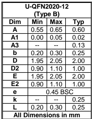
U-QFN2020-12 (Type B)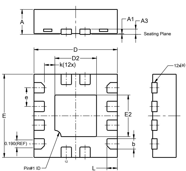
| U-QFN2020-12(Type B) | |||
| Dim | Min | Max | Typ |
| A | 0.55 | 0.65 | 0.60 |
| A1 | 0.00 | 0.05 | 0.02 |
| A3 | -- | -- | 0.13 |
| b | 0.20 | 0.30 | 0.25 |
| D | 1.95 | 2.05 | 2.00 |
| D2 | 0.90 | 1.10 | 1.00 |
| E | 1.95 | 2.05 | 2.00 |
| E2 | 0.90 | 1.10 | 1.00 |
| e | 0.45 BSC | ||
| k | -- | -- | 0.25 |
| L | 0.20 | 0.30 | 0.25 |
| All Dimensions in mm | |||
a) Actual shape depending upon manufacturing technology used
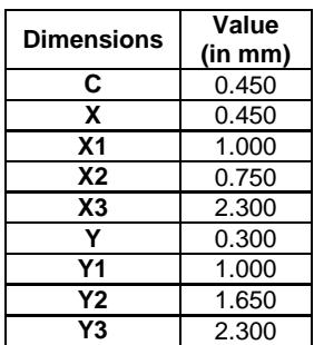
Suggested Pad Layout
Please see http://www.diodes.com/package-outlines.html for the latest version.
U-QFN2020-12 (Type B)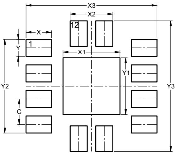
| Dimensions | Value (in mm) |
| C | 0.450 |
| X | 0.450 |
| X1 | 1.000 |
| X2 | 0.750 |
| X3 | 2.300 |
| Y | 0.300 |
| Y1 | 1.000 |
| Y2 | 1.650 |
| Y3 | 2.300 |
Mechanical Data
• Moisture Sensitivity: Level 1 per J-STD-020
Terminals: NiPdAu Finish, Solderable per MIL-STD-202, Method 208
Weight: 0.007 grams (Approximate)
IMPORTANT NOTICE
DIODES INCORPORATED MAKES NO WARRANTY OF ANY KIND, EXPRESS OR IMPLIED, WITH REGARDS TO THIS DOCUMENT, INCLUDING, BUT NOT LIMITED TO, THE IMPLIED WARRANTIES OF MERCHANTABILITY AND FITNESS FOR A PARTICULAR PURPOSE (AND THEIR EQUIVALENTS UNDER THE LAWS OF ANY JURISDICTION).
Diodes Incorporated and its subsidiaries reserve the right to make modifications, enhancements, improvements, corrections or other changes without further notice to this document and any product described herein. Diodes Incorporated does not assume any liability arising out of the application or use of this document or any product described herein; neither does Diodes Incorporated convey any license under its patent or trademark rights, nor the rights of others. Any Customer or user of this document or products described herein in such applications shall assume all risks of such use and will agree to hold Diodes Incorporated and all the companies whose products are represented on Diodes Incorporated website, harmless against all damages.
Diodes Incorporated does not warrant or accept any liability whatsoever in respect of any products purchased through unauthorized sales channel. Should Customers purchase or use Diodes Incorporated products for any unintended or unauthorized application, Customers shall indemnify and hold Diodes Incorporated and its representatives harmless against all claims, damages, expenses, and attorney fees arising out of, directly or indirectly, any claim of personal injury or death associated with such unintended or unauthorized application.
Products described herein may be covered by one or more United States, international or foreign patents pending. Product names and markings noted herein may also be covered by one or more United States, international or foreign trademarks.
This document is written in English but may be translated into multiple languages for reference. Only the English version of this document is the final and determinative format released by Diodes Incorporated.
LIFE SUPPORT
Diodes Incorporated products are specifically not authorized for use as critical components in life support devices or systems without the express written approval of the Chief Executive Officer of Diodes Incorporated. As used herein:
A. Life support devices or systems are devices or systems which:
are intended to implant into the body, o
support or sustain life and whose failure to perform when properly used in accordance with instructions for use provided in the labeling can be reasonably expected to result in significant injury to the user.
B. A critical component is any component in a life support device or system whose failure to perform can be reasonably expected to cause the failure of the life support device or to affect its safety or effectiveness.
Customers represent that they have all necessary expertise in the safety and regulatory ramifications of their life support devices or systems, and acknowledge and agree that they are solely responsible for all legal, regulatory and safety-related requirements concerning their products and any use of Diodes Incorporated products in such safety-critical, life support devices or systems, notwithstanding any devices- or systems-related information or support that may be provided by Diodes Incorporated. Further, Customers must fully indemnify Diodes Incorporated and its representatives against any damages arising out of the use of Diodes Incorporated products in such safety-critical, life support devices or systems.
Copyright © 2020, Diodes Incorporated
Figures and diagrams from the PDF
Preview the extracted datasheet assets and open any image in a separate tab for closer inspection.




Use this datasheet from any agent
Send the page, markdown, chunks, or search endpoint to ChatGPT, Claude, embedr-app, or your own tooling.