
AQY210S
Optically isolated solid-state relay for AC/DC signals, rated for 350 V load voltage and 120 mA continuous load current.
| Miniature SOP4-pin type of 60V/350V/400V load voltage | PhotoMOS®GU SOP 1 Form A (AQY21OS) |
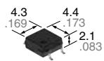
mm inch
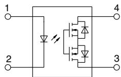
RoHS compliant
FEATURES
Controls low-level analog signals PhotoMOS feature extremely low closedcircuit offset voltage to enable control of low-level analog signals without distortion.
Small SOP4-Pin package
The device comes in a miniature SOP4- pin type measuring (W)4.3 × (L)4.4 × (H)2.1 mm (W).169 × (L).173 × (H).083 inch
Low-level off state leakage current of max. 1 μA
Load voltage 60V, 350V and 400V types available
TYPICAL APPLICATIONS
• Telecommunication (PC, electronic notepad)
• Measuring and testing equipment
• Factory automation equipment
• Security equipment
• Computers
• Industrial robots
TYPES
| Output rating* | Package | Part No. | Packing quantity | |||||
| Load voltage | Load current | Tube packing style | Tape and reel packing style | Tube | Tape and reel | |||
| Picked from the 1/2-pin side | Picked from the 3/4-pin side | |||||||
| AC/DC dual use | 60V | 500mA | SOP4-pin | AQY212S | AQY212SX | AQY212SZ | 1 tube contains: 100 pcs. 1 batch contains: 2,000 pcs. | 1,000 pcs. |
| 350V | 120mA | AQY210S | AQY210SX | AQY210SZ | ||||
| 400V | 100mA | AQY214S | AQY214SX | AQY214SZ | ||||
* Indicate the peak AC and DC values.
Note: For space reasons, the three initial letters of the part number “AQY”, the surface mount terminal indicator “S” and the packing style indicator “X” or “Z” are not marked on the device. (Ex. the label for product number AQY210SX is 210.)
RATING
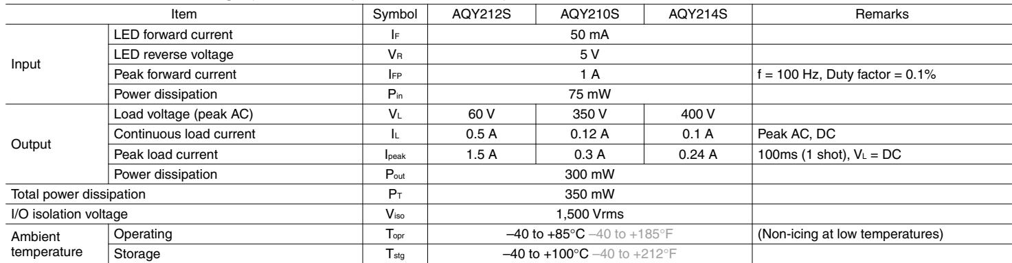
- Absolute maximum ratings (Ambient temperature: 25°C 77°F)
| Item | Symbol | AQY212S | AQY210S | AQY214S | Remarks | |
| Input | LED forward current | $I_F$ | 50 mA | |||
| LED reverse voltage | $V_R$ | 5 V | ||||
| Peak forward current | $I_{FP}$ | 1 A | f = 100 Hz, Duty factor = 0.1% | |||
| Power dissipation | $P_{in}$ | 75 mW | ||||
| Output | Load voltage (peak AC) | $V_L$ | 60 V | 350 V | 400 V | |
| Continuous load current | $I_L$ | 0.5 A | 0.12 A | 0.1 A | Peak AC, DC | |
| Peak load current | $I_{peak}$ | 1.5 A | 0.3 A | 0.24 A | 100ms (1 shot), $V_L$ = DC | |
| Power dissipation | $P_{out}$ | 300 mW | ||||
| Total power dissipation | $P_T$ | 350 mW | ||||
| I/O isolation voltage | $V_{iso}$ | 1,500 Vrms | ||||
| Ambient temperature | Operating | $T_{opr}$ | -40 to +85°C -40 to +185°F | (Non-icing at low temperatures) | ||
| Storage | $T_{stg}$ | -40 to +100°C -40 to +212°F | ||||
GU SOP 1 Form A (AQY21❍S)
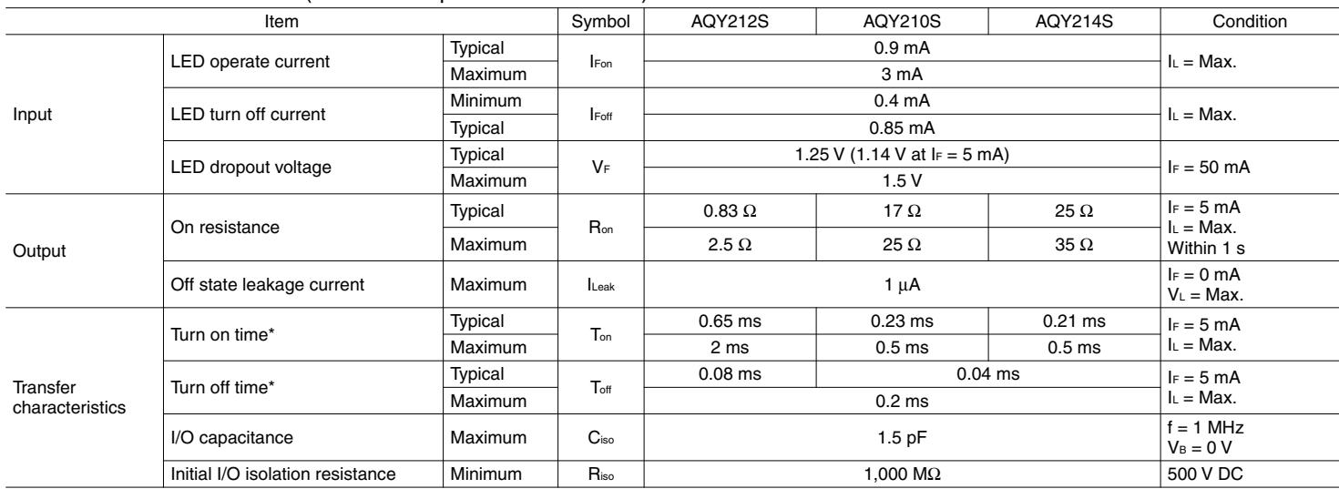
- Electrical characteristics (Ambient temperature: 25°C 77°F)
| Item | Symbol | AQY212S | AQY210S | AQY214S | Condition | ||
| Input | LED operate current | Typical | $I_{Fon}$ | 0.9 mA | $I_L = Max.$ | ||
| Maximum | 3 mA | ||||||
| LED turn off current | Minimum | $I_{Foff}$ | 0.4 mA | $I_L = Max.$ | |||
| Typical | 0.85 mA | ||||||
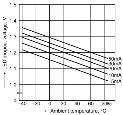
| LED dropout voltage | Typical | $V_F$ | 1.25 V (1.14 V at $I_F = 5 mA$ ) | $I_F = 50 mA$ | |||
| Maximum | 1.5 V | ||||||
| Output | On resistance | Typical | $R_{on}$ | 0.83 Ω | 17 Ω | 25 Ω | $I_F = 5 mA$ $I_L = Max.$ Within 1 s |
| Maximum | 2.5 Ω | 25 Ω | 35 Ω | ||||
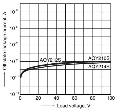
| Off state leakage current | Maximum | $I_{Leak}$ | 1 μA | $I_F = 0 mA$ $V_L = Max.$ | |||
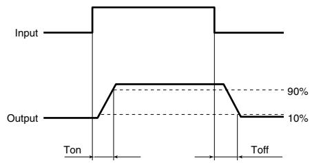
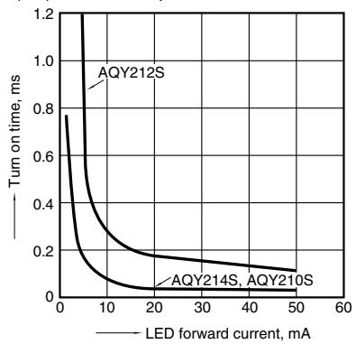
| Transfer characteristics | Turn on time* | Typical | $T_{on}$ | 0.65 ms | 0.23 ms | 0.21 ms | $I_F = 5 mA$ $I_L = Max.$ |
| Maximum | 2 ms | 0.5 ms | 0.5 ms | ||||
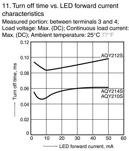
| Turn off time* | Typical | $T_{off}$ | 0.08 ms | 0.04 ms | $I_F = 5 mA$ $I_L = Max.$ | ||
| Maximum | 0.2 ms | ||||||
| I/O capacitance | Maximum | $C_{iso}$ | 1.5 pF | f = 1 MHz $V_B = 0 V$ | |||
| Initial I/O isolation resistance | Minimum | $R_{iso}$ | 1,000 MΩ | 500 V DC | |||
*Turn on/Turn off time
3. Recommended operating conditions (Ambient temperature: $2 5 ^ { \circ } \mathsf { C } 7 7 ^ { \circ } \mathsf { F } )$
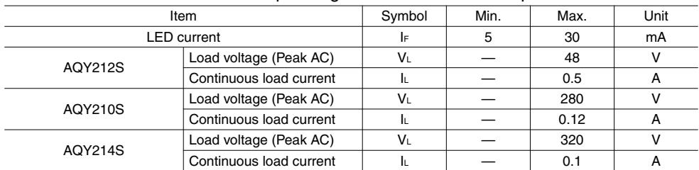
Please use under recommended operating conditions to obtain expected characteristics.
| Item | Symbol | Min. | Max. | Unit | |
| LED current | $I_F$ | 5 | 30 | mA | |
| AQY212S | Load voltage (Peak AC) | $V_L$ | — | 48 | V |
| Continuous load current | $I_L$ | — | 0.5 | A | |
| AQY210S | Load voltage (Peak AC) | $V_L$ | — | 280 | V |
| Continuous load current | $I_L$ | — | 0.12 | A | |
| AQY214S | Load voltage (Peak AC) | $V_L$ | — | 320 | V |
| Continuous load current | $I_L$ | — | 0.1 | A | |
■ These products are not designed for automotive use.
If you are considering to use these products for automotive applications, please contact your local Panasonic Corporation technical representative.
REFERENCE DATA
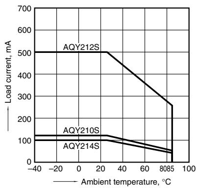
- Load current vs. ambient temperature characteristics Allowable ambient temperature: –40 to +85°C –40 to +185°F
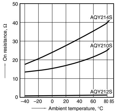
- On resistance vs. ambient temperature characteristics
Measured portion: between terminals 3 and 4; LED current: 5 mA; Load voltage: Max. (DC); Continuous load current: Max. (DC)
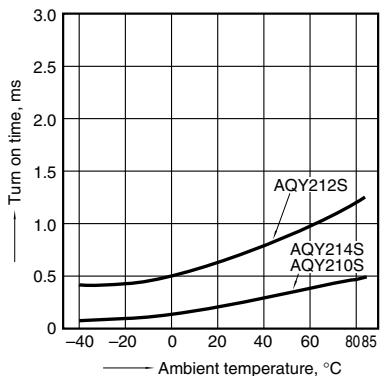
- Turn on time vs. ambient temperature characteristics LED current: 5 mA; Load voltage: Max. (DC); Continuous load current: Max. (DC)
| Current, mA | |
| AQY210S | |
| AQY214S |
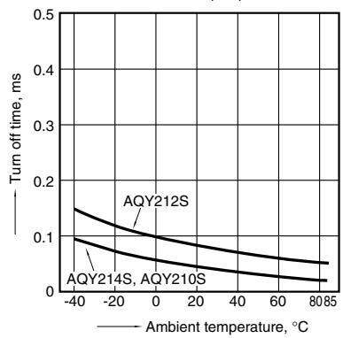
Turn off time vs. ambient temperature characteristics
LED dropout voltage vs. ambient temperature characteristics Sample: All types; LED current: 5 to 50 mA
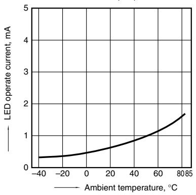
LED operate current vs. ambient temperature characteristics Sample: All types; Load voltage: Max. (DC); Continuous load current: Max. (DC)
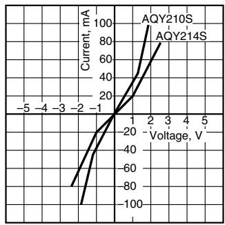
8-(1). Current vs. voltage characteristics of output at MOS portion Measured portion: between terminals 3 and 4; Ambient temperature: 25°C 77°F
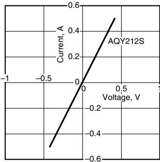
10. Turn on time vs. LED forward current characteristics Measured portion: between terminals 3 and 4; Load voltage: Max. (DC); Continuous load current: Max. (DC); Ambient temperature: 25°C 77°F
- Off state leakage current vs. load voltage characteristics Measured portion: between terminals 3 and 4; Ambient temperature: 25°C 77°F
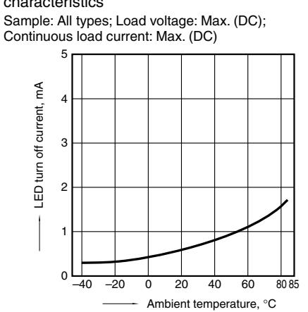
6. LED turn off current vs. ambient temperature characteristics Sample: All types; Load voltage: Max. (DC); Continuous load current: Max. (DC)
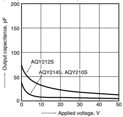
- Output capacitance vs. applied voltage characteristics Measured portion: between terminals 3 and 4; Frequency: 1 MHz; Ambient temperature: 25°C 77°F
8-(2). Current vs. voltage characteristics of output at MOS portion Measured portion: between terminals 3 and 4; Ambient temperature: 25°C 77°F
"PhotoMOS®", "PhotoMOS" and "PHOTOMOS" are registered trademarks of Panasonic Corporation *Recognized in Japan, the United States, all member states of European Union and other countries.
Please contact .....
Panasonic Corporation
Electromechanical Control Business Division ■1006, Oaza Kadoma, Kadoma-shi, Osaka 571-8506, Japan industrial.panasonic.com/ac/e/
Figures and diagrams from the PDF
Preview the extracted datasheet assets and open any image in a separate tab for closer inspection.


Use this datasheet from any agent
Send the page, markdown, chunks, or search endpoint to ChatGPT, Claude, embedr-app, or your own tooling.