
JST S2B-XH-A 2-pin XH Right-Angle Header
JST S2B-XH-A two-circuit XH series side-entry/right-angle through-hole wire-to-board shrouded header with 2.5 mm pitch.
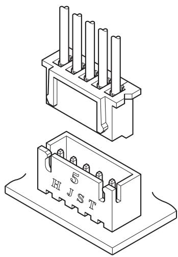
Highly reliable, versatile 2.5 mm pitch wire-toboard connector with an assembled board height of 9.8 mm for low profile applications.
・Original double-leaf contact design
・Box-shaped shrouded header
・Header is also available with boss
・The 4 pin version conforms to JEMA's Home Automation (HA terminal) standards.
Specifications
• Current rating: 3 A AC/DC(AWG #22)
・Voltage rating: 250 V AC/DC
・Temperature range: -25℃ to +85℃ (including temperature rise in applying electrical current)
・Contact resistance:Initial value/ 10 mΩ max.After environmental tests/ 20 mΩ max.
・Insulation resistance: 1,000 MΩ min.
・Withstanding voltage: There shall be no breakdown or flashover while applying 1,000 VAC for one minute.
・Applicable wire range: Conductor size/ AWG #30 to AWG #22 Insulation O.D./ φ 0.9 mm to φ 1.9 mm
・Applicable PC board thickness: 1.6 mm
* Please refer to the "Handling Precautions for Terminals and Connectors" on our website (listed in the “Technical Documents” column on the Product Information page) before use.
* RoHS2 compliance
* Dimensional unit: mm
* Contact JST for details.
■ Standards
For information on overseas standard registrations, please refer to the "List of Registered Overseas Standards" on our website (listed in the “Technical Documents” column on the Product Information page).
* Specifications registered to overseas standards may differ from the general specifications listed above.
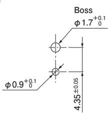
PC board layout and Assembly layout
Top entry type <Single circuit>
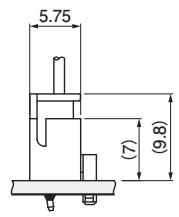
< 2 circuits or more>
±0.05 2 circuits: φ1 3 circuits or more: φ0.9+0.1 0
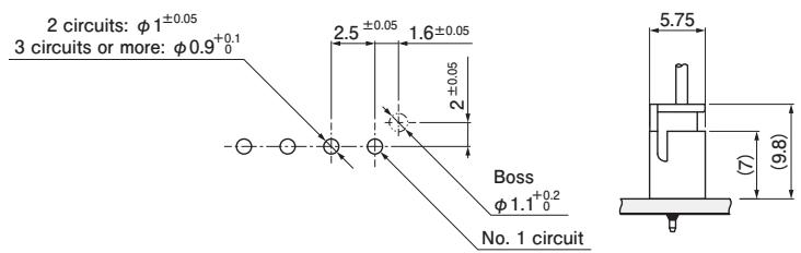
Side entry type
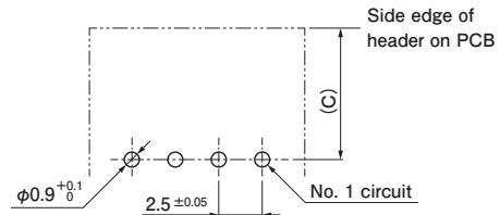
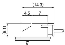
Note: 1. The PC board layout figure shown is viewed from the connector mounting surface.
Tolerance for the PCB hole pitch shal $\mathsf { b e } \pm 0 . 0 5$ and shall not accumulate.
Dimension C: See “Header/ Side entry $\mathsf { t y p e } ^ { \ast }$ section on page 4.
Hole dimensions differ depending on the type of PCB and PCB drilling method. 4. Hole dimensions differ depending on the type of PCB and PCB drilling method.
When using PCB made of hard material composed of fiberglass cloth, please consider a larger hole diameter. The above dimensions are reference values. Please contact JST for details.
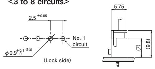
PC board layout and Assembly layout/ PA 66(Glass-filled) type, Radial tape type
Top entry type
<2 circuits>
<3 to 8 circuits>
<9 circuits or more>
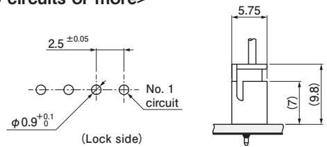
Note: 1. The PC board layout figure shown is viewed from the connector mounting surface.
Tolerance for the PCB hole pitch shall $\mathsf { b e } \pm 0 . 0 5$ and shall not accumulate.
Radial tape style packaging conforms to PCB hole diameter specifications on the automatic insertion machine.
Hole dimensions differ depending on the type of PCB and PCB drilling method.
When using PCB made of hard material composed of fiberglass cloth with glass-filled PA 66, please consider a larger hole diameter.
The above dimensions are reference values. Please contact JST for details
PC board layout and Assembly layout/ SMT type
Side entry type
Material and Surface finish, etc.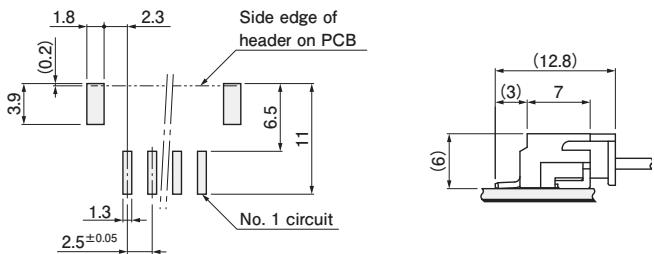
Note: 1. The PC board layout figure shown is viewed from the connector mounting surface.
Tolerance for the PCB pattern pitch shall be ± 0.05 and shall not accumulate.
The above dimensions are reference values. Please contact JST for details.
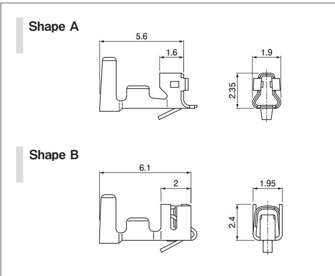
Contact
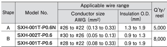
| Shape | Model No. | Applicable wire range | Q'ty/reel | |
| Conductor size AWG (mm2) | Insulation O.D. (mm) | |||
| A | SXH-001T-P0.6N | #26 to #22 (0.13 to 0.33) | 1.3 to 1.9 | 5,000 |
| B | SXH-002T-P0.6 | #30 to #26 (0.05 to 0.13) | 0.9 to 1.3 | 8,000 |
| SXH-001T-P0.6 | #28 to #22 (0.08 to 0.33) | 0.9 to 1.9 | ||
Phosphor bronze, tin-plated
Note: 1. Contact JST for gold-plated products.
Contact JST also if you require shielded wires, thin wires or other special wires.
SXH-001T-P0.6N is low-insertion force type contact, for easier insertion/withdrawal, which would be less resistant to the vibration.
Crimping machine
| Contact | Crimping machine | Applicator | Crimp applicator with dies |
| SXH-001T-P0.6N | AP-K2N | MKS-L | APLMK SXH001-06N |
| SXH-002T-P0.6 | APLMK SXH002-06 | ||
| SXH-001T-P0.6 | APLMK SXH001-06 |
Note: Contact JST for fully automatic crimping applicator.
Housing
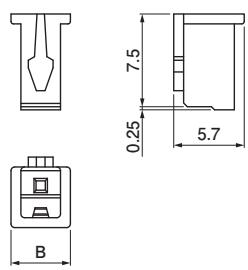
<2 to 16, 20 circuits>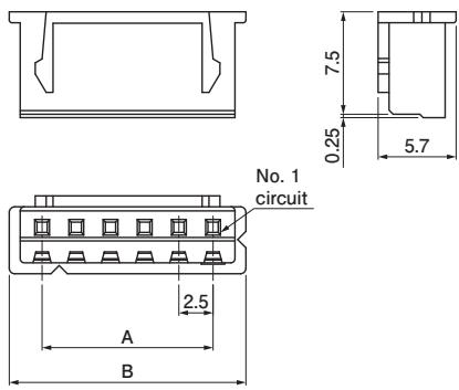
Plugged up hole
<2 circuits, 10 mm pitch>
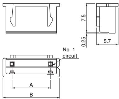
<6 circuits, 5 mm pitch>
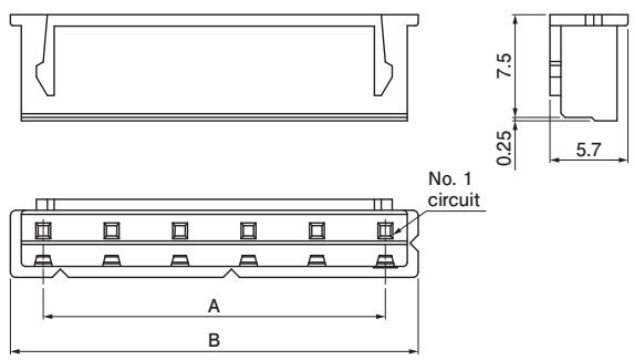
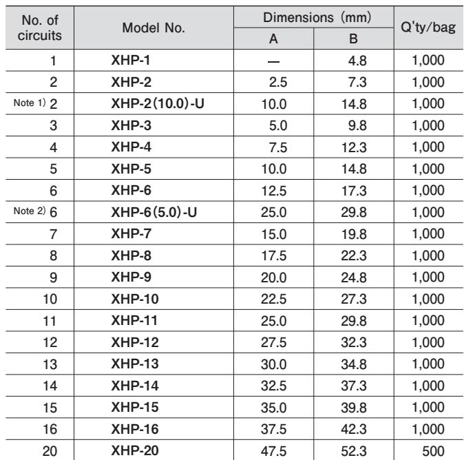
| No. of circuits | Model No. | Dimensions (mm) | Q'ty/bag | |
| A | B | |||
| 1 | XHP-1 | — | 4.8 | 1,000 |
| 2 | XHP-2 | 2.5 | 7.3 | 1,000 |
| Note 1) 2 | XHP-2(10.0)-U | 10.0 | 14.8 | 1,000 |
| 3 | XHP-3 | 5.0 | 9.8 | 1,000 |
| 4 | XHP-4 | 7.5 | 12.3 | 1,000 |
| 5 | XHP-5 | 10.0 | 14.8 | 1,000 |
| 6 | XHP-6 | 12.5 | 17.3 | 1,000 |
| Note 2) 6 | XHP-6(5.0)-U | 25.0 | 29.8 | 1,000 |
| 7 | XHP-7 | 15.0 | 19.8 | 1,000 |
| 8 | XHP-8 | 17.5 | 22.3 | 1,000 |
| 9 | XHP-9 | 20.0 | 24.8 | 1,000 |
| 10 | XHP-10 | 22.5 | 27.3 | 1,000 |
| 11 | XHP-11 | 25.0 | 29.8 | 1,000 |
| 12 | XHP-12 | 27.5 | 32.3 | 1,000 |
| 13 | XHP-13 | 30.0 | 34.8 | 1,000 |
| 14 | XHP-14 | 32.5 | 37.3 | 1,000 |
| 15 | XHP-15 | 35.0 | 39.8 | 1,000 |
| 16 | XHP-16 | 37.5 | 42.3 | 1,000 |
| 20 | XHP-20 | 47.5 | 52.3 | 500 |
Material and Surface finish, etc.
PA 6, natural (white)
Note: 1. XHP-2(10.0)-U means the 2-circuits housing with 10.0 mm pitch, and 3-circuits of 5-circuits are filled with the resin
XHP-6(5.0)-U means the 6-circuits housing with 5.0 mm pitch and each even number circuit is filled with the resin.
For flame retardant grade of resin material used, please refer to the "List of Registered Overseas Standards" on our website (listed in the “Technical Documents” column on the Product Information page).
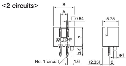
Header
Top entry type <Single circuit>
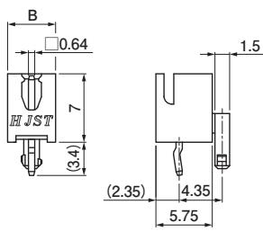
<3 circuits or more>
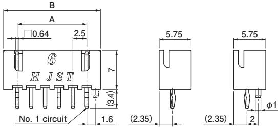
Top entry type, plugged up hole
<2 circuits, 10 mm pitch>
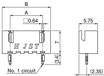
Side entry type
<2 circuits>
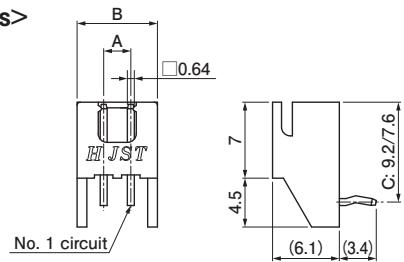
<3 circuits or more>
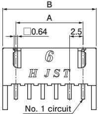
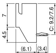
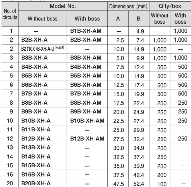
Top entry type
| No. of circuits | Model No. | Dimensions (mm) | Q'ty/box | |||
| Without boss | With boss | A | B | Without boss | With boss | |
| 1 | — | B1B-XH-AM | — | 4.9 | — | 1,000 |
| 2 | B2B-XH-A | B2B-XH-AM | 2.5 | 7.4 | 1,000 | 1,000 |
| 2 | B2(10.0)B-XH-A-U Note2) | — | 10.0 | 14.9 | 1,000 | — |
| 3 | B3B-XH-A | B3B-XH-AM | 5.0 | 9.9 | 1,000 | 1,000 |
| 4 | B4B-XH-A | B4B-XH-AM | 7.5 | 12.4 | 500 | 500 |
| 5 | B5B-XH-A | B5B-XH-AM | 10.0 | 14.9 | 500 | 500 |
| 6 | B6B-XH-A | B6B-XH-AM | 12.5 | 17.4 | 500 | 500 |
| 7 | B7B-XH-A | B7B-XH-AM | 15.0 | 19.9 | 500 | 500 |
| 8 | B8B-XH-A | B8B-XH-AM | 17.5 | 22.4 | 250 | 250 |
| 9 | B9B-XH-A | B9B-XH-AM | 20.0 | 24.9 | 250 | 250 |
| 10 | B10B-XH-A | B10B-XH-AM | 22.5 | 27.4 | 250 | 250 |
| 11 | B11B-XH-A | — | 25.0 | 29.9 | 250 | — |
| 12 | B12B-XH-A | B12B-XH-AM | 27.5 | 32.4 | 250 | 250 |
| 13 | B13B-XH-A | — | 30.0 | 34.9 | 250 | — |
| 14 | B14B-XH-A | — | 32.5 | 37.4 | 250 | — |
| 15 | B15B-XH-A | — | 35.0 | 39.9 | 250 | — |
| 16 | B16B-XH-A | — | 37.5 | 42.4 | 200 | — |
| 20 | B20B-XH-A | — | 47.5 | 52.4 | 100 | — |
Material and Surface finish, etc.
Post: Brass, copper-undercoated, tin-plated Wafer: PA 66, natural (white)
Note: 1. This product displays (LF)(SN) on a label.
B2(10.0)B-XH-A-U means the 2-circuits housing with 10.0 mm pitch, and 3-circuits of 5-circuits are filled with the resin.
For flame retardant grade of resin material used, please refer to the "List of Registered Overseas Standards" on our website (listed in the “Technical Documents” column on the Product Information page).
Side entry type
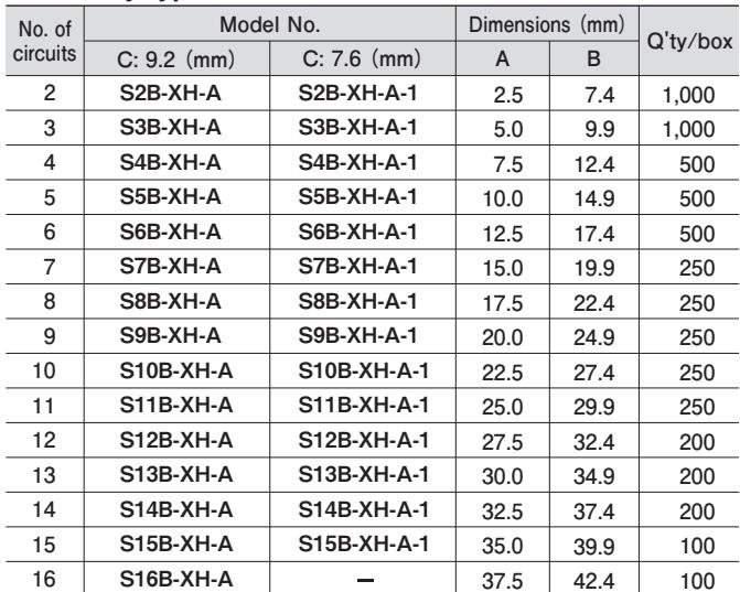
| No. of circuits | Model No. | Dimensions (mm) | Q'ty/box | ||
| C: 9.2 (mm) | C: 7.6 (mm) | A | B | ||
| 2 | S2B-XH-A | S2B-XH-A-1 | 2.5 | 7.4 | 1,000 |
| 3 | S3B-XH-A | S3B-XH-A-1 | 5.0 | 9.9 | 1,000 |
| 4 | S4B-XH-A | S4B-XH-A-1 | 7.5 | 12.4 | 500 |
| 5 | S5B-XH-A | S5B-XH-A-1 | 10.0 | 14.9 | 500 |
| 6 | S6B-XH-A | S6B-XH-A-1 | 12.5 | 17.4 | 500 |
| 7 | S7B-XH-A | S7B-XH-A-1 | 15.0 | 19.9 | 250 |
| 8 | S8B-XH-A | S8B-XH-A-1 | 17.5 | 22.4 | 250 |
| 9 | S9B-XH-A | S9B-XH-A-1 | 20.0 | 24.9 | 250 |
| 10 | S10B-XH-A | S10B-XH-A-1 | 22.5 | 27.4 | 250 |
| 11 | S11B-XH-A | S11B-XH-A-1 | 25.0 | 29.9 | 250 |
| 12 | S12B-XH-A | S12B-XH-A-1 | 27.5 | 32.4 | 200 |
| 13 | S13B-XH-A | S13B-XH-A-1 | 30.0 | 34.9 | 200 |
| 14 | S14B-XH-A | S14B-XH-A-1 | 32.5 | 37.4 | 200 |
| 15 | S15B-XH-A | S15B-XH-A-1 | 35.0 | 39.9 | 100 |
| 16 | S16B-XH-A | — | 37.5 | 42.4 | 100 |
Material and Surface finish, etc.
Post: Brass, copper-undercoated, tin-plated Wafer: PA 66, natural (white)
Note: 1. This product displays (LF)(SN) on a label.
- For flame retardant grade of resin material used, please refer to the "List of Registered Overseas Standards" on our website (listed in the “Technical Documents” column on the Product Information page).
XH CONNECTOR
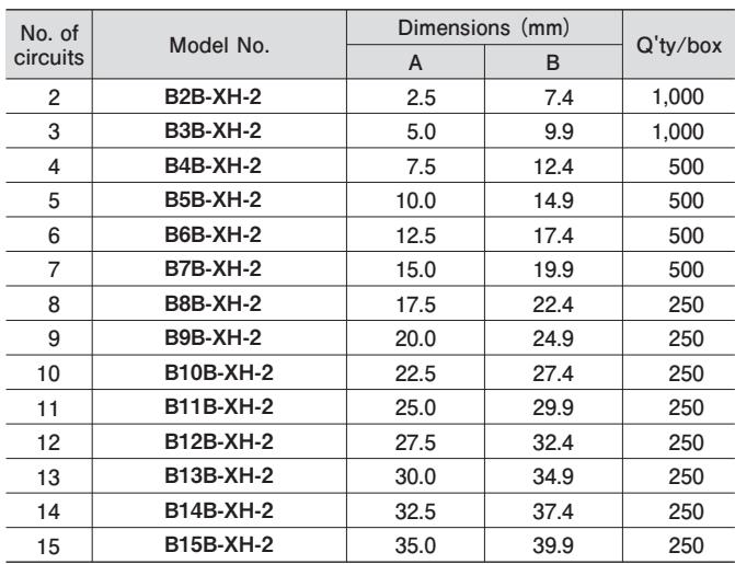
Header/ PA 66 (Glass-filled) type
Top entry type <2 circuits>
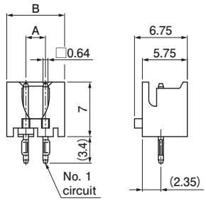
<3 to 8 circuits>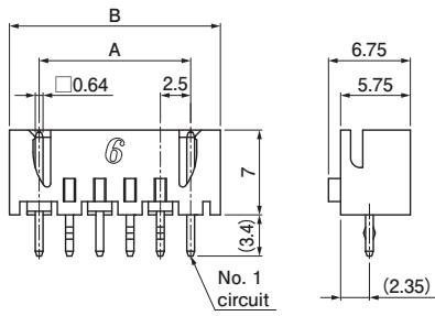
| No. of circuits | Model No. | Dimensions (mm) | Q'ty/box | |
| A | B | |||
| 2 | B2B-XH-2 | 2.5 | 7.4 | 1,000 |
| 3 | B3B-XH-2 | 5.0 | 9.9 | 1,000 |
| 4 | B4B-XH-2 | 7.5 | 12.4 | 500 |
| 5 | B5B-XH-2 | 10.0 | 14.9 | 500 |
| 6 | B6B-XH-2 | 12.5 | 17.4 | 500 |
| 7 | B7B-XH-2 | 15.0 | 19.9 | 500 |
| 8 | B8B-XH-2 | 17.5 | 22.4 | 250 |
| 9 | B9B-XH-2 | 20.0 | 24.9 | 250 |
| 10 | B10B-XH-2 | 22.5 | 27.4 | 250 |
| 11 | B11B-XH-2 | 25.0 | 29.9 | 250 |
| 12 | B12B-XH-2 | 27.5 | 32.4 | 250 |
| 13 | B13B-XH-2 | 30.0 | 34.9 | 250 |
| 14 | B14B-XH-2 | 32.5 | 37.4 | 250 |
| 15 | B15B-XH-2 | 35.0 | 39.9 | 250 |
Material and Surface finish, etc.
Post: Brass, copper-undercoated, tin-plated Wafer: PA 66 (Glass-filled), natural (ivory)
Note: 1. This product displays (LF)(SN) on a label
- For flame retardant grade of resin material used, please refer to the "List of Registered Overseas Standards" on our website (listed in the “Technical Documents” column on the Product Information page).
<9 circuits or more>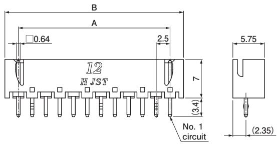
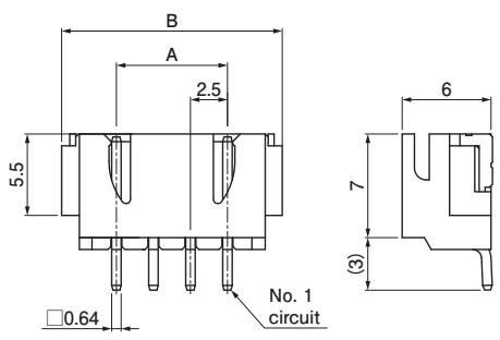
Header/ SMT type
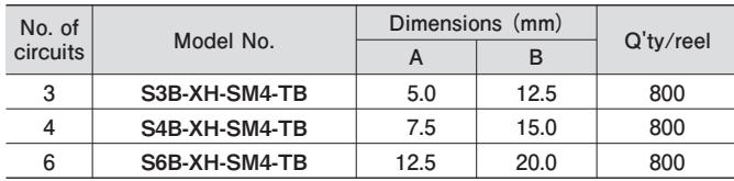
| No. of circuits | Model No. | Dimensions (mm) | Q'ty/reel | |
| A | B | |||
| 3 | S3B-XH-SM4-TB | 5.0 | 12.5 | 800 |
| 4 | S4B-XH-SM4-TB | 7.5 | 15.0 | 800 |
| 6 | S6B-XH-SM4-TB | 12.5 | 20.0 | 800 |
Material and Surface finish, etc.
Post: Copper alloy, copper-undercoated, tin-plated Wafer: Modified PA 6T, natural (ivory) Solder tab: Brass, copper-undercoated, tin-plated
Note: 1. This product displays (LF)(SN) on a label.
This product is supplied on embossed tape and reel packaging.
For flame retardant grade of resin material used, please refer to the "List of Registered Overseas Standards" on our website (listed in the “Technical Documents” column on the Product Information page).
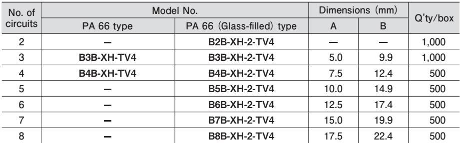
Header/ Radial tape type
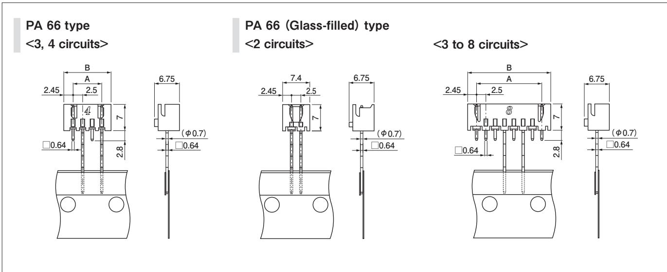
| No. of circuits | Model No. | Dimensions (mm) | Q'ty/box | ||
| PA 66 type | PA 66 (Glass-filled) type | A | B | ||
| 2 | — | B2B-XH-2-TV4 | — | — | 1,000 |
| 3 | B3B-XH-TV4 | B3B-XH-2-TV4 | 5.0 | 9.9 | 1,000 |
| 4 | B4B-XH-TV4 | B4B-XH-2-TV4 | 7.5 | 12.4 | 500 |
| 5 | — | B5B-XH-2-TV4 | 10.0 | 14.9 | 500 |
| 6 | — | B6B-XH-2-TV4 | 12.5 | 17.4 | 500 |
| 7 | — | B7B-XH-2-TV4 | 15.0 | 19.9 | 500 |
| 8 | — | B8B-XH-2-TV4 | 17.5 | 22.4 | 500 |
Material and Surface finish, etc.
Post: Brass, copper-undercoated, tin-plated Wafer: PA 66 type/ PA 66, natural (white) PA 66 (Glass-filled) type/ PA 66 (Glass-filled), natural (ivory)
Note: 1. This product displays (LF)(SN) on a label.
- For flame retardant grade of resin material used, please refer to the "List of Registered Overseas Standards" on our website (listed in the “Technical Documents” column on the Product Information page).
Taping specifications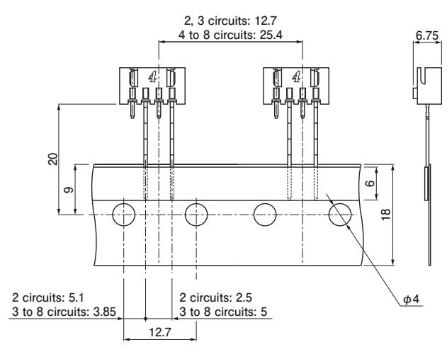
Note: Conforms to IEC 60286-2 (JIC C 0806-2) "Tape packaging of components with unidirectional leads on continuous tapes".
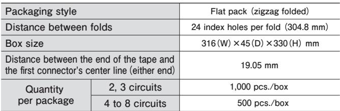
Packaging specifications
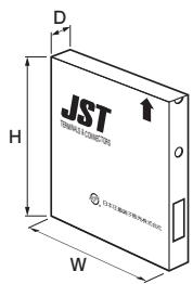
Distance between the end of the tape and the first connector's center line (either end)
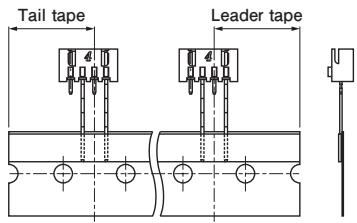
| Packaging style | Flat pack (zigzag folded) | |
| Distance between folds | 24 index holes per fold (304.8 mm) | |
| Box size | 316 (W) × 45 (D) × 330 (H) mm | |
| Distance between the end of the tape and the first connector's center line (either end) | 19.05 mm | |
| Quantity per package | 2, 3 circuits | 1,000 pcs./box |
| 4 to 8 circuits | 500 pcs./box | |
Note: Products of different packaging specifications are also available. Contact JST for details.
Model number allocation
Contact
002…AWG #30 to AWG #26
001…AWG #28 to AWG #22
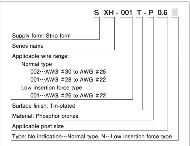
Low insertion force type
001…AWG #26 to AWG #22
Surface finish: Tin-plated
Material: Phosphor bronze
Applicable post size
Type: No indication…Normal type, N…Low insertion force type
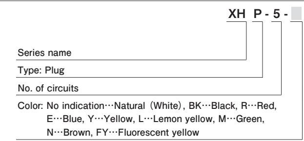
Housing
| XH | P - 5 - | |
| Series name | ||
| Type: Plug | ||
| No. of circuits | ||
| Color: No indication...Natural (White), BK...Black, R...Red,E...Blue, Y...Yellow, L...Lemon yellow, M...Green,N...Brown, FY...Fluorescent yellow | ||
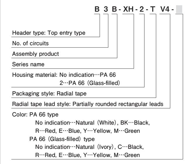
Header/ Radial tape type
Model number allocation
Housing/ Plugged up hole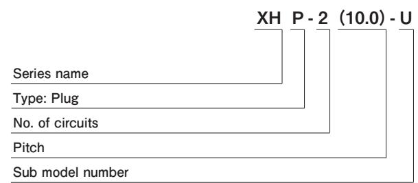
Type: Plug
Header/ Plugged up hole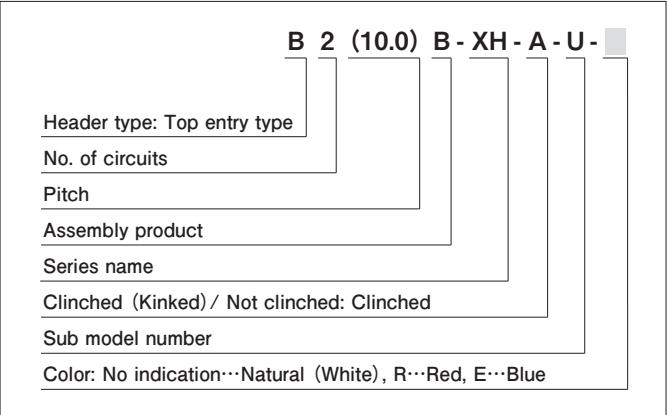
No. of circuits
Series name
Sub model number
No. of circuits
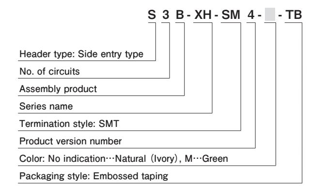
Product version number
Color: No indication…Natural (Ivory), M…Green
Packaging style: Embossed taping
Header/ SMT type
Header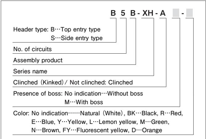
Clinched (Kinked)/ Not clinched: Clinched
Header/ PA 66 (Glass-filled) type
B 5 B 2- XH --
No. of circuits
Assembly product
Series name
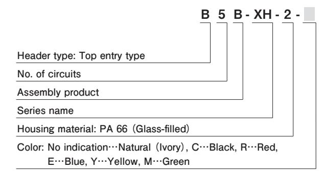
Housing material: PA 66 (Glass-filled)
Color: No indication…Natural (Ivory), C…Black, R…Red,
E…Blue, Y…Yellow, M…Green
Header type: Top entry type
No. of circuits
Assembly product
Packaging style: Radial tape
Radial tape lead style: Partially rounded rectangular leads
Color: PA 66 type
No indication…Natural (White), BK…Black,
R…Red, E…Blue, Y…Yellow, M…Green
PA 66 (Glass-filled) type
No indication…Natural (Ivory), C…Black,
R…Red, E…Blue, Y…Yellow, M…Green
Figures and diagrams from the PDF
Preview the extracted datasheet assets and open any image in a separate tab for closer inspection.

Use this datasheet from any agent
Send the page, markdown, chunks, or search endpoint to ChatGPT, Claude, embedr-app, or your own tooling.