
Adafruit 326 0.96 inch 128x64 SSD1306 OLED Display
Adafruit PID 326 0.96 inch 128x64 monochrome SSD1306 OLED breakout with STEMMA QT / Qwiic I2C connectors, 1x8 through-hole header, I2C default configuration, and optional SPI wiring.
Product Specification
Part Name: OEL Display Module
Part ID: UG-2864HSWEG01
Doc No.: SAS1-9046-B
Customer:
Approved by

From: Univision Technology Inc.
Approved by
Univision Technology Inc.
8, Kebei RD 2, Science Park, Chu-Nan, Taiwan 350, R.O.C.
Notes:
Please contact Univision Technology Inc. before assigning your product based on this module specification
The information contained herein is presented merely to indicate the characteristics and performance of our products. No responsibility is assumed by Univision Technology Inc. for any intellectual property claims or other problems that may result from application based on the module described herein.
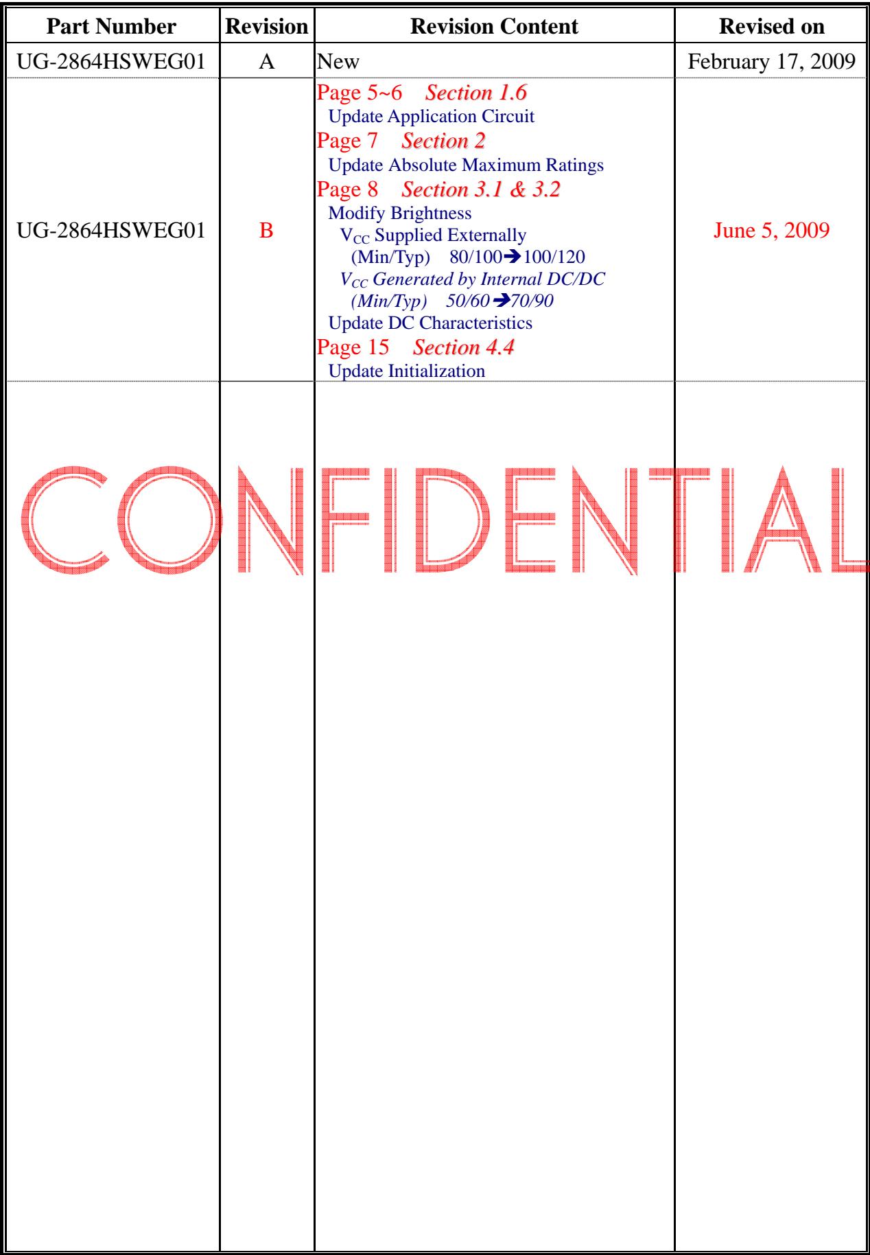
Revised History
| Part Number | Revision | Revision Content | Revised on |
| UG-2864HSWEG01 | A | New | February 17, 2009 |
| UG-2864HSWEG01 | B | Page 5~6 Section 1.6Update Application CircuitPage 7 Section 2Update Absolute Maximum RatingsPage 8 Section 3.1 & 3.2Modify Brightness $V_{CC}$ Supplied Externally(Min/Typ) 80/100→100/120 $V_{CC}$ Generated by Internal DC/DC(Min/Typ) 50/60→70/90Update DC CharacteristicsPage 15 Section 4.4Update Initialization | June 5, 2009 |
CONFIDENTIAL
Notice:
No part of this material may be reproduces or duplicated in any form or by any means without the written permission of Univision Technology Inc. Univision Technology Inc. reserves the right to make changes to this material without notice. Univision Technology Inc. does not assume any liability of any kind arising out of any inaccuracies contained in this material or due to its application or use in any product or circuit and, further, there is no representation that this material is applicable to products requiring high level reliability, such as, medical products. Moreover, no license to any intellectual property rights is granted by implication or otherwise, and there is no representation or warranty that anything made in accordance with this material will be free from any patent or copyright infringement of a third party. This material or portions thereof may contain technology or the subject relating to strategic products under the control of Foreign Exchange and Foreign Trade Law of Taiwan and may require an export license from the Ministry of International Trade and Industry or other approval from another government agency.
© Univision Technology Inc. 2009, All rights reserved.
All other product names mentioned herein are trademarks and/or registered trademarks of their respective companies.
Contents
Revision History ....i
Notice ....ii
Contents ....iii
Basic Specifications ....1~6
1.1 Display Specifications ....1
1.2 Mechanical Specifications ....1
1.3 Active Area & Pixel Construction ....1
1.4 Mechanical Drawing ....2
1.5 Pin Definition ....3
1.6 Block Diagram ....5
1.6.1 Vcc Supplied Externally ....5
1.6.2 Vcc Generated by Internal DC/DC Circuit ....6Absolute Maximum Ratings ....7
Optics & Electrical Characteristics ....8~13
3.1 Optics Characteristics ....8
3.2 DC Characteristics ....8
3.3 AC Characteristics ....9
3.3.1 68XX-Series MPU Parallel Interface Timing Characteristics ....9
3.3.2 80XX-Series MPU Parallel Interface Timing Characteristics ....10
3.3.3 Serial Interface Timing Characteristics (4-wire SPI)....11
3.3.4 Serial Interface Timing Characteristics (3-wire SPI)....12
3.3.5 I²C Interface Timing Characteristics ....13Functional Specification ....14~15
4.1 Commands ....14
4.2 Power down and Power up Sequence ....14
4.2.1 Power up Sequence ....14
4.2.2 Power down Sequence ....14
4.3 Reset Circuit ....14
4.4 Actual Application Example ....15Reliability ....16
5.1 Contents of Reliability Tests ....16
5.2 Lifetime ....16
5.3 Failure Check Standard ....16Outgoing Quality Control Specifications ....17~21
6.1 Environment Required ....17
6.2 Sampling Plan ....17
6.3 Criteria & Acceptable Quality Level ....17
6.3.1 Cosmetic Check (Display Off) in Non-Active Area ....17
6.3.2 Cosmetic Check (Display Off) in Active Area....20
6.3.3 Pattern Check (Display On) in Active Area....21
7. Package Specifications....22
8. Precautions When Using These OEL Display Modules....23~25
8.1 Handling Precautions....23
8.2 Storage Precautions....24
8.3 Designing Precautions....24
8.4 Precautions when disposing of the OEL display modules....25
8.5 Other Precautions....25
1. Basic Specifications
1.1 Display Specifications
Display Mode: Passive Matrix
Display Color: Monochrome (White)
Drive Duty: 1/64 Duty
1.2 Mechanical Specifications
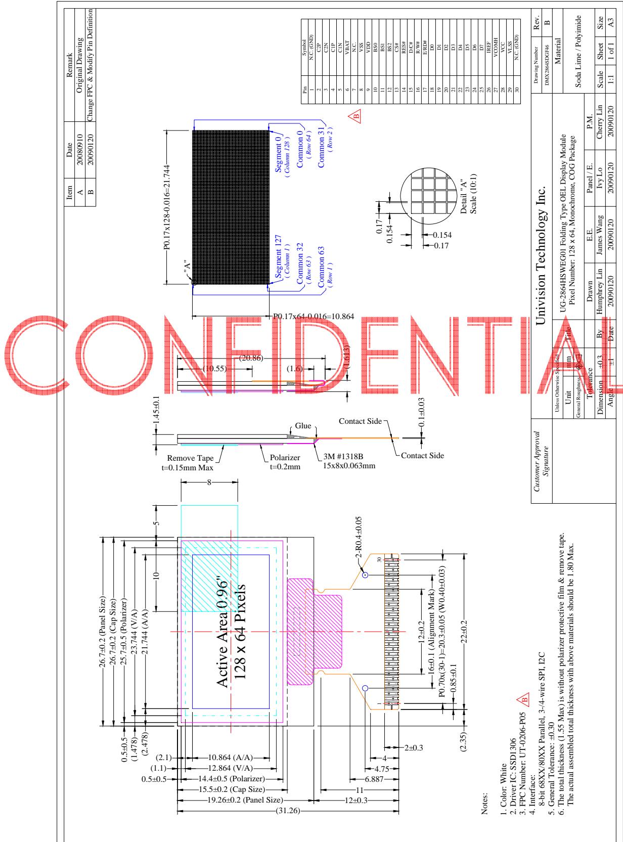
Outline Drawing: According to the annexed outline drawing
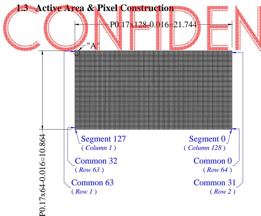
Number of Pixels: $128 \times 64$
Panel Size: $26.70 \times 19.26 \times 1.45 , (\text{mm})$
Active Area: $21.744 \times 10.864 , (\text{mm})$
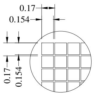
Pixel Pitch: $0.17 \times 0.17 , (\text{mm})$
Pixel Size: $0.154 \times 0.154 , (\text{mm})$
Weight: 1.54 (g)

1.4 Mechanical Drawing
1.5 Pin Definition
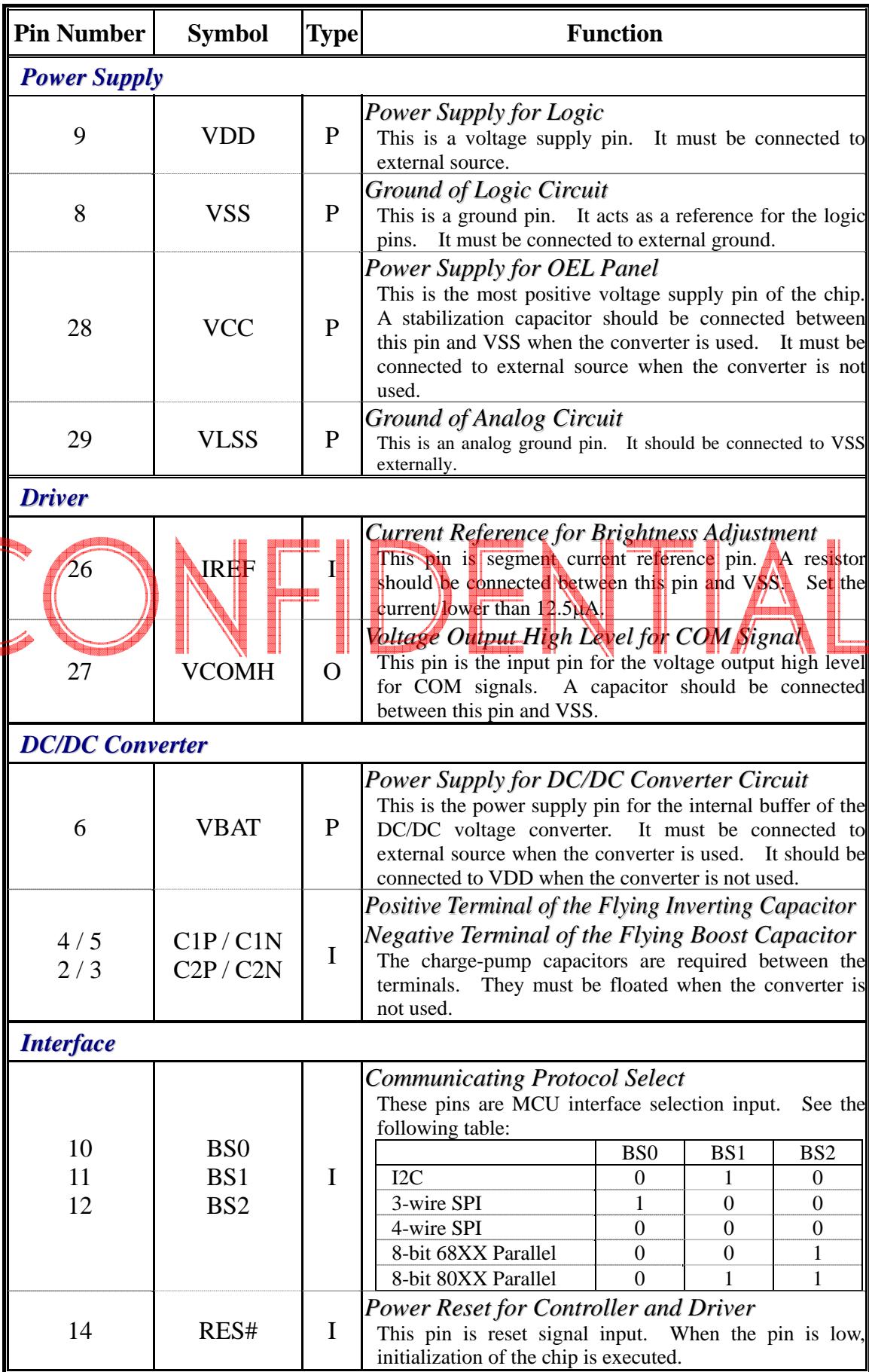
| Pin Number | Symbol | Type | Function | |||
| Power Supply | ||||||
| 9 | VDD | P | Power Supply for LogicThis is a voltage supply pin. It must be connected to external source. | |||
| 8 | VSS | P | Ground of Logic CircuitThis is a ground pin. It acts as a reference for the logic pins. It must be connected to external ground. | |||
| 28 | VCC | P | Power Supply for OEL PanelThis is the most positive voltage supply pin of the chip.A stabilization capacitor should be connected between this pin and VSS when the converter is used. It must be connected to external source when the converter is not used. | |||
| 29 | VLSS | P | Ground of Analog CircuitThis is an analog ground pin. It should be connected to VSS externally. | |||
| Driver | ||||||
| 26 | IREF | I | Current Reference for Brightness AdjustmentThis pin is segment current reference pin. A resistor should be connected between this pin and VSS. Set the current/lower than 12.5μA. | |||
| 27 | VCOMH | O | Voltage Output High Level for COM SignalThis pin is the input pin for the voltage output high level for COM signals. A capacitor should be connected between this pin and VSS. | |||
| DC/DC Converter | ||||||
| 6 | VBAT | P | Power Supply for DC/DC Converter CircuitThis is the power supply pin for the internal buffer of the DC/DC voltage converter. It must be connected to external source when the converter is used. It should be connected to VDD when the converter is not used. | |||
| 4/5 | C1P/C1N | I | Positive Terminal of the Flying Inverting CapacitorNegative Terminal of the Flying Boost CapacitorThe charge-pump capacitors are required between the terminals. They must be floated when the converter is not used. | |||
| 2/3 | C2P/C2N | |||||
| Interface | ||||||
| 10 | BS0 | I | Communicating Protocol SelectThese pins are MCU interface selection input. See the following table: | |||
| 11 | BS1 | BS0 | BS1 | BS2 | ||
| 12 | BS2 | I2C | 0 | 1 | 0 | |
| 3-wire SPI | 1 | 0 | 0 | |||
| 4-wire SPI | 0 | 0 | 0 | |||
| 8-bit 68XX Parallel | 0 | 0 | 1 | |||
| 8-bit 80XX Parallel | 0 | 1 | 1 | |||
| 14 | RES# | I | Power Reset for Controller and DriverThis pin is reset signal input. When the pin is low, initialization of the chip is executed. | |||
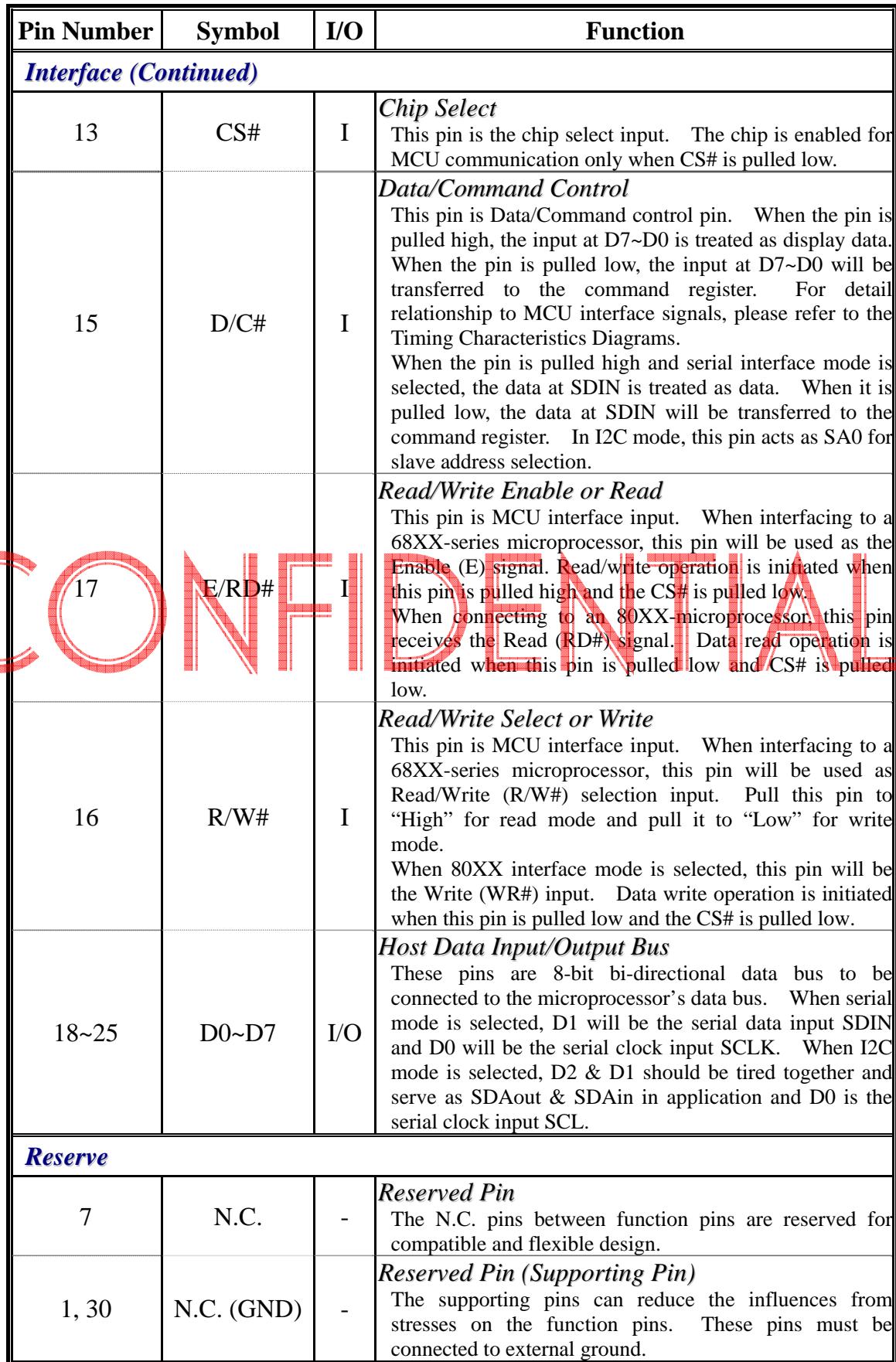
| Pin Number | Symbol | I/O | Function | |||
| Interface (Continued) | ||||||
| 13 | CS# | I | Chip SelectThis pin is the chip select input. The chip is enabled for MCU communication only when CS# is pulled low. | |||
| 15 | D/C# | I | Data/Command ControlThis pin is Data/Command control pin. When the pin is pulled high, the input at D7~D0 is treated as display data. When the pin is pulled low, the input at D7~D0 will be transferred to the command register. For detail relationship to MCU interface signals, please refer to the Timing Characteristics Diagrams.When the pin is pulled high and serial interface mode is selected, the data at SDIN is treated as data. When it is pulled low, the data at SDIN will be transferred to the command register. In I2C mode, this pin acts as SA0 for slave address selection. | |||
| 17 | E/RD# | I | Read/Write Enable or ReadThis pin is MCU interface input. When interfacing to a 68XX-series microprocessor, this pin will be used as the Enable (E) signal. Read/write operation is initiated when this pin is pulled high and the CS# is pulled low.When connecting to an 80XX-microprocessor, this pin receives the Read (RD#) signal. Data read operation is initiated when this pin is pulled low and CS# is pulled low. | |||
| 16 | R/W# | I | Read/Write Select or WriteThis pin is MCU interface input. When interfacing to a 68XX-series microprocessor, this pin will be used as Read/Write (R/W#) selection input. Pull this pin to “High” for read mode and pull it to “Low” for write mode.When 80XX interface mode is selected, this pin will be the Write (WR#) input. Data write operation is initiated when this pin is pulled low and the CS# is pulled low. | |||
| 18~25 | D0~D7 | I/O | Host Data Input/Output BusThese pins are 8-bit bi-directional data bus to be connected to the microprocessor’s data bus. When serial mode is selected, D1 will be the serial data input SDIN and D0 will be the serial clock input SCLK. When I2C mode is selected, D2 & D1 should be tired together and serve as SDAout & SDAin in application and D0 is the serial clock input SCL. | |||
| Reserve | ||||||
| 7 | N.C. | - | Reserved PinThe N.C. pins between function pins are reserved for compatible and flexible design. | |||
| 1, 30 | N.C. (GND) | - | Reserved Pin (Supporting Pin)The supporting pins can reduce the influences from stresses on the function pins. These pins must be connected to external ground. | |||
1.6 Block Diagram
1.6.1 $V_{cc}$ Supplied Externally
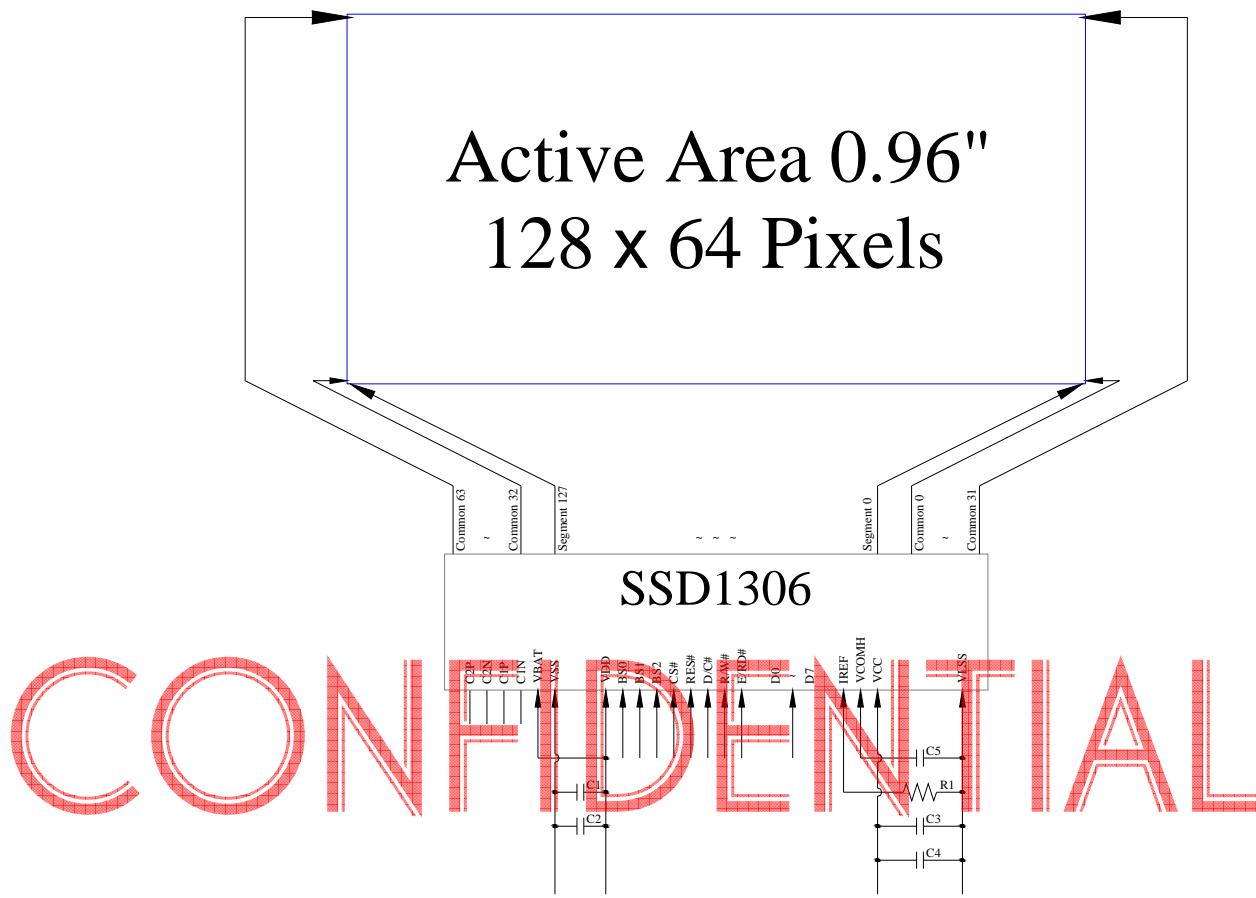
Active Area 0.96" 128 x 64 Pixels
SSD1306
MCU Interface Selection:
BS0, BS1 and BS2
Pins connected to MCU interface: CS#, RES#, D/C#, R/W#, E/RD#, and D0~D7
C1, C3: 0.1μF
C2: $2.2\mu F$
C4, C5: $4.7\mu F / 16V$ , X7R
R1: 560kΩ, R1 = (Voltage at IREF - VSS) / IREF
1.6.2 $V_{CC}$ Generated by Internal DC/DC Circuit
Active Area 0.96" 128 x 64 Pixels
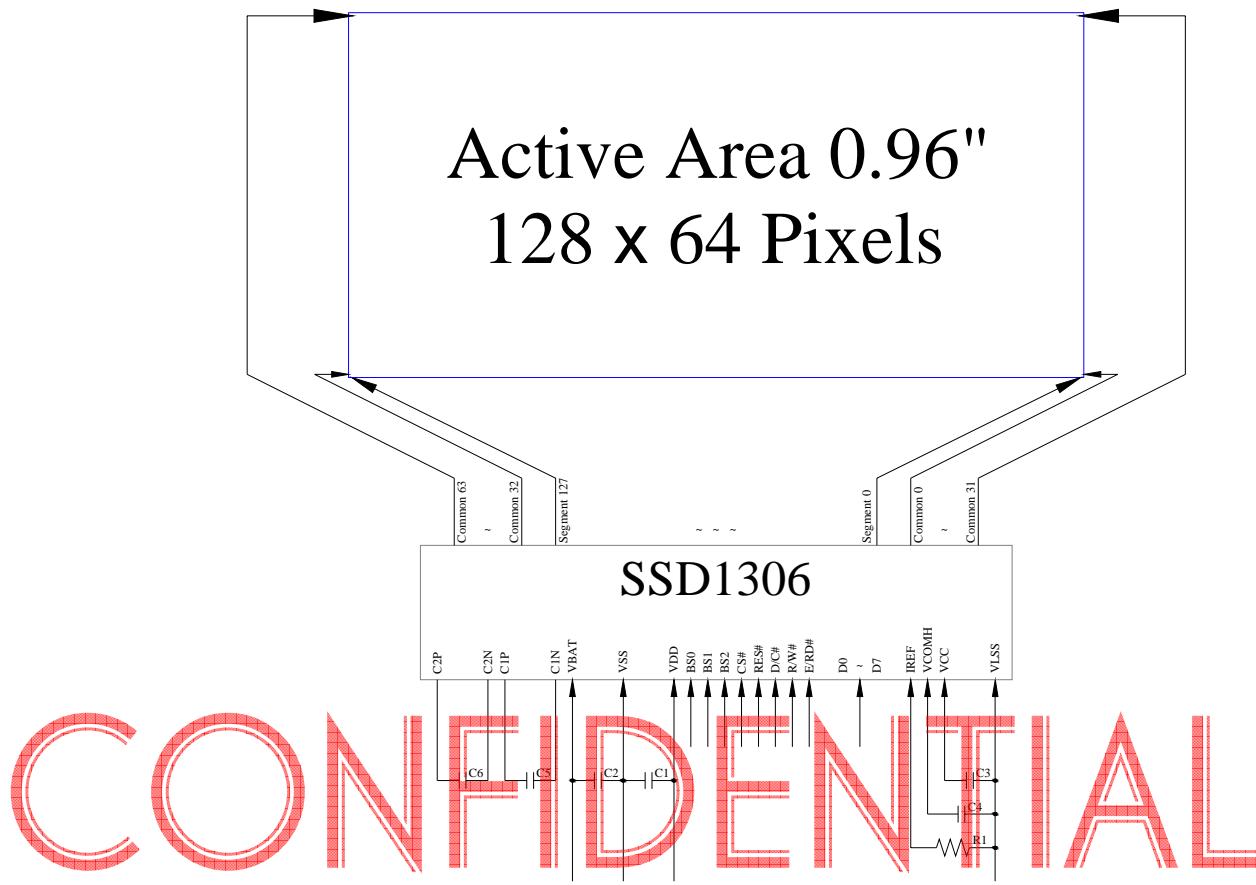
MCU Interface Selection:
BS0, BS1 and BS2
Pins connected to MCU interface: CS#, RES#, D/C#, R/W#, E/RD#, and D0~D7
C1, C2, C5, C6: $1\mu F$
C3: $2.2\mu F$
C4: $4.7\mu F / 16V, X7R$
R1: $390k\Omega$ , R1 = (Voltage at IREF - VSS) / IREF
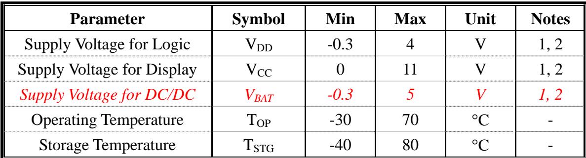
2. Absolute Maximum Ratings
| Parameter | Symbol | Min | Max | Unit | Notes |
| Supply Voltage for Logic | $V_{DD}$ | -0.3 | 4 | V | 1, 2 |
| Supply Voltage for Display | $V_{CC}$ | 0 | 11 | V | 1, 2 |
| Supply Voltage for DC/DC | $V_{BAT}$ | -0.3 | 5 | V | 1, 2 |
| Operating Temperature | $T_{OP}$ | -30 | 70 | °C | - |
| Storage Temperature | $T_{STG}$ | -40 | 80 | °C | - |
Note 1: All the above voltages are on the basis of “VSS = 0V”.
Note 2: When this module is used beyond the above absolute maximum ratings, permanent breakage of the module may occur. Also, for normal operations, it is desirable to use this module under the conditions according to Section 3. "Optics & Electrical Characteristics". If this module is used beyond these conditions, malfunctioning of the module can occur and the reliability of the module may deteriorate.

3. Optics & Electrical Characteristics
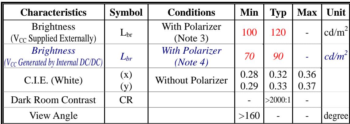
3.1 Optics Characteristics
| Characteristics | Symbol | Conditions | Min | Typ | Max | Unit |
| Brightness(VCC Supplied Externally) | $L_{br}$ | With Polarizer(Note 3) | 100 | 120 | - | cd/m2 |
| Brightness(VCC Generated by Internal DC/DC) | $L_{br}$ | With Polarizer(Note 4) | 70 | 90 | - | cd/m2 |
| C.I.E. (White) | (x)(y) | Without Polarizer | 0.280.29 | 0.320.33 | 0.360.37 | |
| Dark Room Contrast | CR | - | >2000:1 | - | ||
| View Angle | >160 | - | - | degree |
* Optical measurement taken at $V_{DD} = 2.8V$ , $V_{CC} = 9V$ & 7.25V.
Software configuration follows Section 4.4 Initialization.
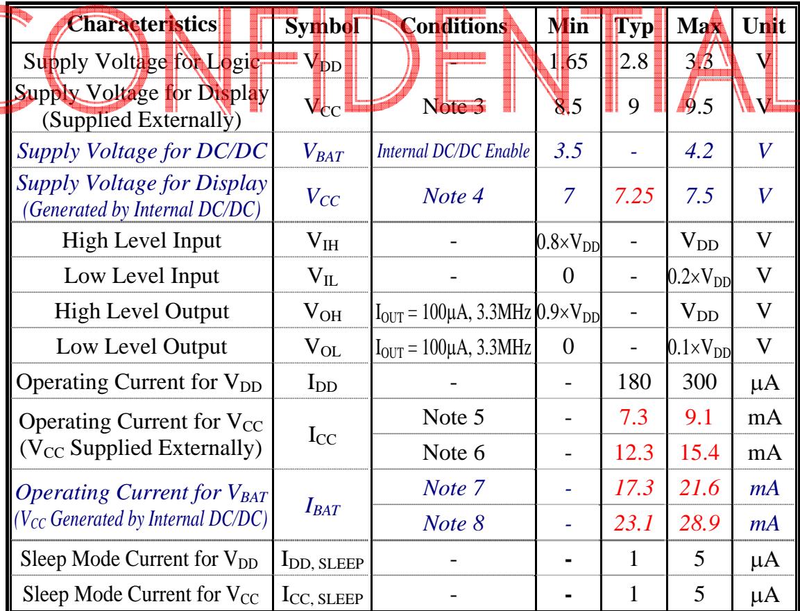
3.2 DC Characteristics
| Characteristics | Symbol | Conditions | Min | Typ | Max | Unit |
| Supply Voltage for Logic | $V_{DD}$ | - | 1.65 | 2.8 | 3.3 | V |
| Supply Voltage for Display (Supplied Externally) | $V_{CC}$ | Note 3 | 8.5 | 9 | 9.5 | V |
| Supply Voltage for DC/DC | $V_{BAT}$ | Internal DC/DC Enable | 3.5 | - | 4.2 | V |
| Supply Voltage for Display (Generated by Internal DC/DC) | $V_{CC}$ | Note 4 | 7 | 7.25 | 7.5 | V |
| High Level Input | $V_{IH}$ | - | 0.8× $V_{DD}$ | - | $V_{DD}$ | V |
| Low Level Input | $V_{IL}$ | - | 0 | - | 0.2× $V_{DD}$ | V |
| High Level Output | $V_{OH}$ | IOUT=100μA, 3.3MHz | 0.9× $V_{DD}$ | - | $V_{DD}$ | V |
| Low Level Output | $V_{OL}$ | IOUT=100μA, 3.3MHz | 0 | - | 0.1× $V_{DD}$ | V |
| Operating Current for $V_{DD}$ | $I_{DD}$ | - | - | 180 | 300 | μA |
| Operating Current for $V_{CC}$ ( $V_{CC}$ Supplied Externally) | $I_{CC}$ | Note 5 | - | 7.3 | 9.1 | mA |
| Note 6 | - | 12.3 | 15.4 | mA | ||
| Operating Current for $V_{BAT}$ ( $V_{CC}$ Generated by Internal DC/DC) | $I_{BAT}$ | Note 7 | - | 17.3 | 21.6 | mA |
| Note 8 | - | 23.1 | 28.9 | mA | ||
| Sleep Mode Current for $V_{DD}$ | $I_{DD, SLEEP}$ | - | - | 1 | 5 | μA |
| Sleep Mode Current for $V_{CC}$ | $I_{CC, SLEEP}$ | - | - | 1 | 5 | μA |
Note 3 & 4: Brightness ( $L_{br}$ ) and Supply Voltage for Display ( $V_{CC}$ ) are subject to the
change of the panel characteristics and the customer's request.
Note 5: $V_{DD} = 2.8V$ , $V_{CC} = 9V$ , 50% Display Area Turn on.
Note 6: $V_{DD} = 2.8V$ , $V_{CC} = 9V$ , 100% Display Area Turn on.
Note 7: $V_{DD} = 2.8V$ , $V_{CC} = 7.25V$ , 50% Display Area Turn on.
Note 8: $V_{DD} = 2.8V$ , $V_{CC} = 7.25V$ , 100% Display Area Turn on.
* Software configuration follows Section 4.4 Initialization.
3.3 AC Characteristics
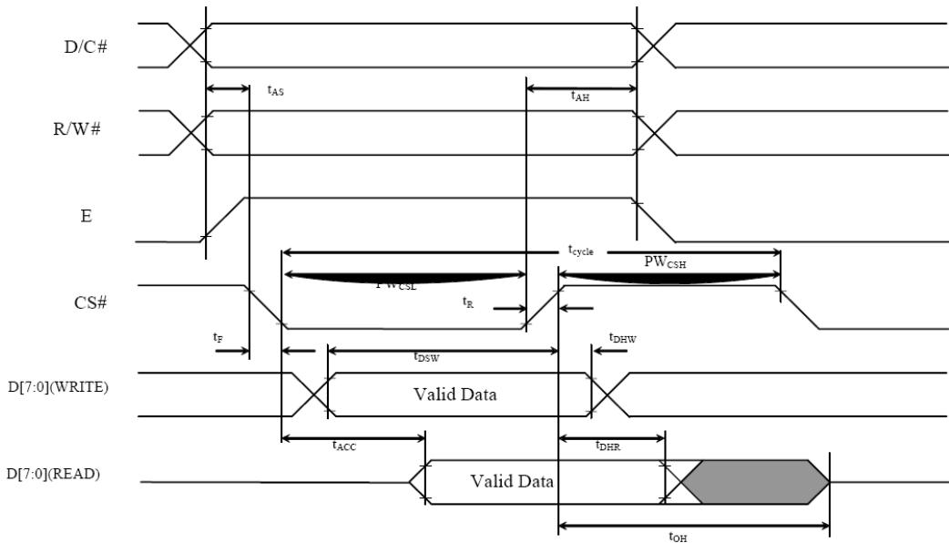
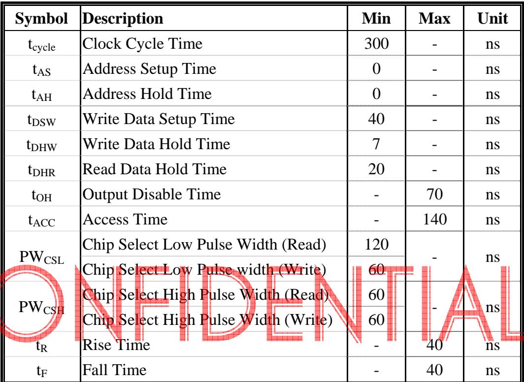
3.3.1 68XX-Series MPU Parallel Interface Timing Characteristics:
| Symbol | Description | Min | Max | Unit |
| $t_{cycle}$ | Clock Cycle Time | 300 | - | ns |
| $t_{AS}$ | Address Setup Time | 0 | - | ns |
| $t_{AH}$ | Address Hold Time | 0 | - | ns |
| $t_{DSW}$ | Write Data Setup Time | 40 | - | ns |
| $t_{DHW}$ | Write Data Hold Time | 7 | - | ns |
| $t_{DHR}$ | Read Data Hold Time | 20 | - | ns |
| $t_{OH}$ | Output Disable Time | - | 70 | ns |
| $t_{ACC}$ | Access Time | - | 140 | ns |
| $PW_{CSL}$ | Chip Select Low Pulse Width (Read) | 120 | - | ns |
| Chip Select Low Pulse width (Write) | 60 | |||
| $PW_{CSH}$ | Chip Select High Pulse Width (Read) | 60 | - | ns |
| Chip Select High Pulse Width (Write) | 60 | |||
| $t_{R}$ | Rise Time | - | 40 | ns |
| $t_{F}$ | Fall Time | - | 40 | ns |
* $(\mathrm{V_{DD} - V_{SS}} = 1.65\mathrm{V}$ to $3.3\mathrm{V},\mathrm{T_a} = 25^{\circ}\mathrm{C})$
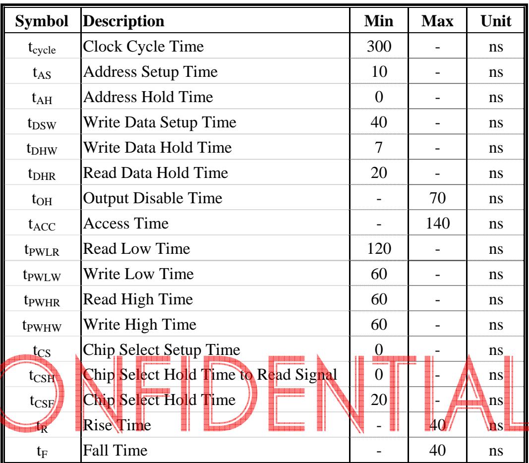
3.3.2 80XX-Series MPU Parallel Interface Timing Characteristics:
| Symbol | Description | Min | Max | Unit |
| $t_{cycle}$ | Clock Cycle Time | 300 | - | ns |
| $t_{AS}$ | Address Setup Time | 10 | - | ns |
| $t_{AH}$ | Address Hold Time | 0 | - | ns |
| $t_{DSW}$ | Write Data Setup Time | 40 | - | ns |
| $t_{DHW}$ | Write Data Hold Time | 7 | - | ns |
| $t_{DHR}$ | Read Data Hold Time | 20 | - | ns |
| $t_{OH}$ | Output Disable Time | - | 70 | ns |
| $t_{ACC}$ | Access Time | - | 140 | ns |
| $t_{PWLR}$ | Read Low Time | 120 | - | ns |
| $t_{PWLW}$ | Write Low Time | 60 | - | ns |
| $t_{PWHR}$ | Read High Time | 60 | - | ns |
| $t_{PWHW}$ | Write High Time | 60 | - | ns |
| $t_{CS}$ | Chip Select Setup Time | 0 | - | ns |
| $t_{CSH}$ | Chip Select Hold Time to Read Signal | 0 | - | ns |
| $t_{CSF}$ | Chip Select Hold Time | 20 | - | ns |
| $t_{R}$ | Rise Time | - | 40 | ns |
| $t_{F}$ | Fall Time | - | 40 | ns |
* $(\mathrm{V_{DD} - V_{SS}} = 1.65\mathrm{V}$ to $3.3\mathrm{V},\mathrm{T_a} = 25^{\circ}\mathrm{C})$
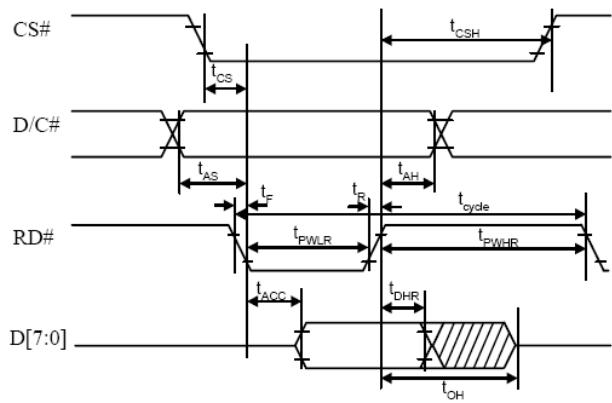
( Read Timing )
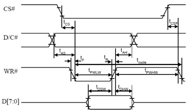
(Write Timing)
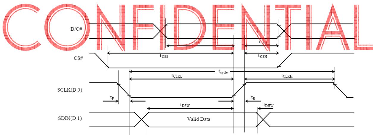
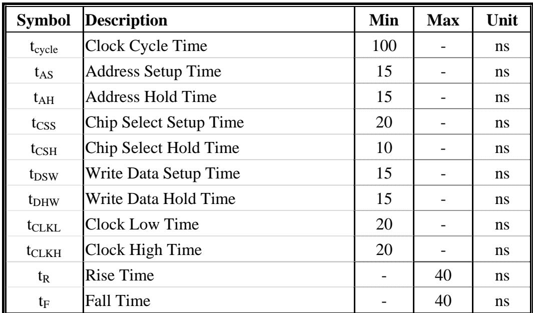
3.3.3 Serial Interface Timing Characteristics: (4-wire SPI)
| Symbol | Description | Min | Max | Unit |
| $t_{cycle}$ | Clock Cycle Time | 100 | - | ns |
| $t_{AS}$ | Address Setup Time | 15 | - | ns |
| $t_{AH}$ | Address Hold Time | 15 | - | ns |
| $t_{CSS}$ | Chip Select Setup Time | 20 | - | ns |
| $t_{CSH}$ | Chip Select Hold Time | 10 | - | ns |
| $t_{DSW}$ | Write Data Setup Time | 15 | - | ns |
| $t_{DHW}$ | Write Data Hold Time | 15 | - | ns |
| $t_{CLKL}$ | Clock Low Time | 20 | - | ns |
| $t_{CLKH}$ | Clock High Time | 20 | - | ns |
| $t_{R}$ | Rise Time | - | 40 | ns |
| $t_{F}$ | Fall Time | - | 40 | ns |
* $(\mathrm{V_{DD} - V_{SS}} = 1.65\mathrm{V}$ to $3.3\mathrm{V},\mathrm{T_a} = 25^{\circ}\mathrm{C})$

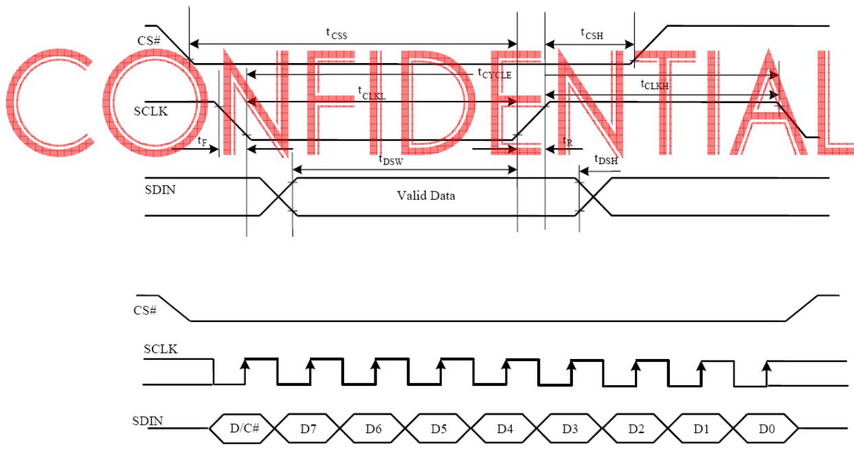
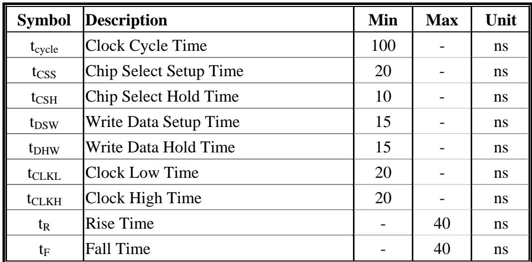
3.3.4 Serial Interface Timing Characteristics: (3-wire SPI)
| Symbol | Description | Min | Max | Unit |
| $t_{cycle}$ | Clock Cycle Time | 100 | - | ns |
| $t_{CSS}$ | Chip Select Setup Time | 20 | - | ns |
| $t_{CSH}$ | Chip Select Hold Time | 10 | - | ns |
| $t_{DSW}$ | Write Data Setup Time | 15 | - | ns |
| $t_{DHW}$ | Write Data Hold Time | 15 | - | ns |
| $t_{CLKL}$ | Clock Low Time | 20 | - | ns |
| $t_{CLKH}$ | Clock High Time | 20 | - | ns |
| $t_R$ | Rise Time | - | 40 | ns |
| $t_F$ | Fall Time | - | 40 | ns |
* $(\mathrm{V_{DD} - V_{SS}} = 1.65\mathrm{V}$ to $3.3\mathrm{V},\mathrm{T_a} = 25^{\circ}\mathrm{C})$
Univision Technology Inc.
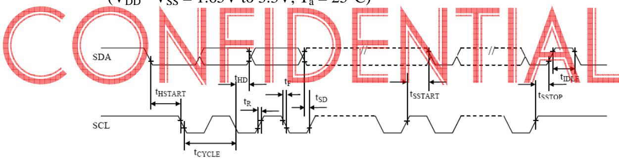
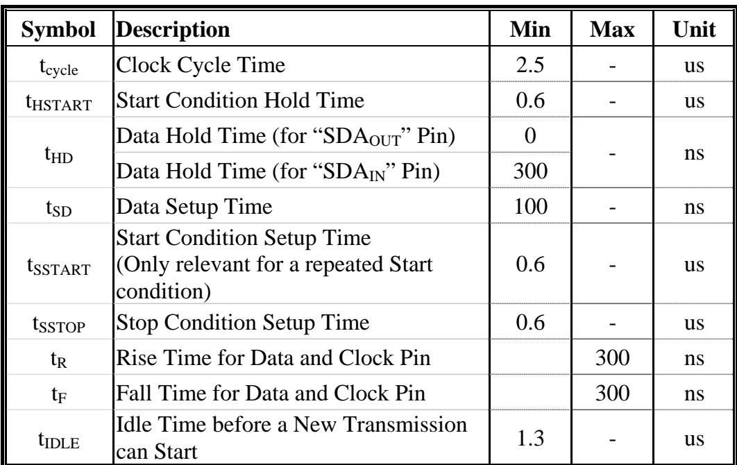
3.3.5 I $^{2}$ C Interface Timing Characteristics:
| Symbol | Description | Min | Max | Unit |
| $t_{cycle}$ | Clock Cycle Time | 2.5 | - | us |
| $t_{HSTART}$ | Start Condition Hold Time | 0.6 | - | us |
| $t_{HD}$ | Data Hold Time (for “SDAOUT” Pin) | 0 | - | ns |
| Data Hold Time (for “SDAIN” Pin) | 300 | |||
| $t_{SD}$ | Data Setup Time | 100 | - | ns |
| $t_{SSTART}$ | Start Condition Setup Time(Only relevant for a repeated Start condition) | 0.6 | - | us |
| $t_{SSTOP}$ | Stop Condition Setup Time | 0.6 | - | us |
| $t_{R}$ | Rise Time for Data and Clock Pin | 300 | ns | |
| $t_{F}$ | Fall Time for Data and Clock Pin | 300 | ns | |
| $t_{IDLE}$ | Idle Time before a New Transmission can Start | 1.3 | - | us |
* $(\mathrm{V_{DD} - V_{SS}} = 1.65\mathrm{V}$ to $3.3\mathrm{V},\mathrm{T_a} = 25^{\circ}\mathrm{C})$
4. Functional Specification
4.1. Commands
Refer to the Technical Manual for the SSD1306
4.2 Power down and Power up Sequence
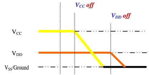
To protect OEL panel and extend the panel life time, the driver IC power up/down routine should include a delay period between high voltage and low voltage power sources during turn on/off. It gives the OEL panel enough time to complete the action of charge and discharge before/after the operation.
4.2.1 Power up Sequence:
Power up $V_{DD}$
Send Display off command
Initialization
Clear Screen
Power up $V_{CC}$

4.2.2 Power down Sequence:
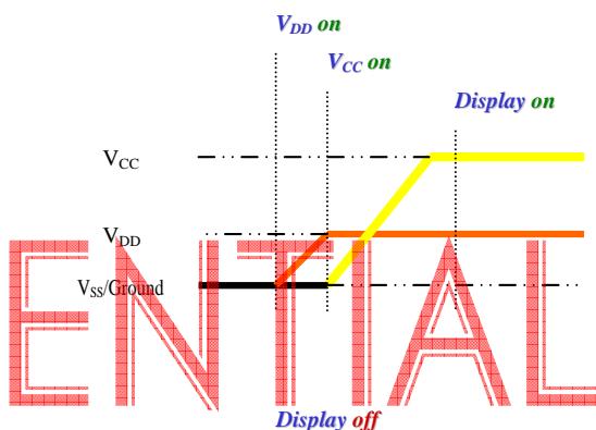
Send Display off command
Power down $V_{cc}$
Delay 100ms
(When $V_{CC}$ is reach 0 and panel is completely discharges)Power down $V_{DD}$
4.3 Reset Circuit
When RES# input is low, the chip is initialized with the following status:
Display is OFF
128×64 Display Mode
Normal segment and display data column and row address mapping (SEG0 mapped to column address 00h and COM0 mapped to row address 00h)
Shift register data clear in serial interface
Display start line is set at display RAM address 0
Column address counter is set at 0
Normal scan direction of the COM outputs
Contrast control register is set at 7Fh
Normal display mode (Equivalent to A4h command)
4.4 Actual Application Example
Command usage and explanation of an actual example
<Initialization>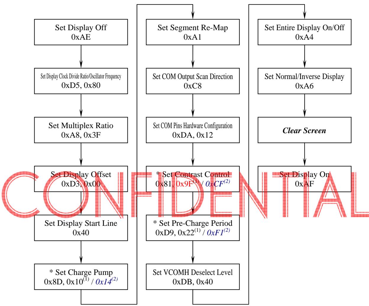
* Written Value for Parameters
(1) $\rightarrow V_{CC}$ Supplied Externally
$^{(2)}$ $\rightarrow V_{CC}$ Generated by Internal DC/DC Circuit
If the noise is accidentally occurred at the displaying window during the operation, please reset the display in order to recover the display function.
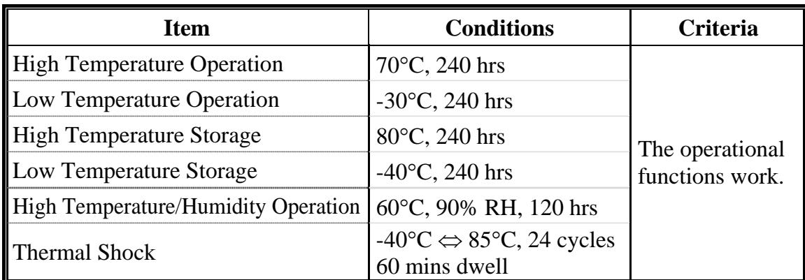
5. Reliability
5.1 Contents of Reliability Tests
| Item | Conditions | Criteria |
| High Temperature Operation | 70°C, 240 hrs | The operational functions work. |
| Low Temperature Operation | -30°C, 240 hrs | |
| High Temperature Storage | 80°C, 240 hrs | |
| Low Temperature Storage | -40°C, 240 hrs | |
| High Temperature/Humidity Operation | 60°C, 90% RH, 120 hrs | |
| Thermal Shock | -40°C ⇔ 85°C, 24 cycles 60 mins dwell |
* The samples used for the above tests do not include polarizer.
* No moisture condensation is observed during tests.
5.2 Lifetime
| Parameter | Min | Max | Unit | Condition | Notes |
| Operating Life Time | 10,000 | - | hr | $100 \text{ cd/m}^{2}, 50\% \text{ Checkerboard}$ | 6 |
| Storage Life Time | 20,000 | - | hr | $T_{a} = 25^{\circ}\text{C}, 50\% \text{ RH}$ | - |
Note 6: The average operating lifetime at room temperature is estimated by the accelerated operation at high temperature conditions.
5.3 Failure Check Standard
After the completion of the described reliability test, the samples were left at room temperature for 2 hrs prior to conducting the failure test at $23 \pm 5^{\circ}C$ ; $55 \pm 15%$ RH.
6. Outgoing Quality Control Specifications
6.1 Environment Required
Customer's test & measurement are required to be conducted under the following conditions:
Temperature: $23 \pm 5^{\circ}C$
Humidity: $55 \pm 15 %RH$
Fluorescent Lamp: 30W
Distance between the Panel & Lamp: $\geq$ 50 cm
Distance between the Panel & Eyes of the Inspector: $\geq$ 30 cm
Finger glove (or finger cover) must be worn by the inspector.
Inspection table or jig must be anti-electrostatic.
6.2 Sampling Plan
Level II, Normal Inspection, Single Sampling, MIL-STD-105E
| Partition | AQL | Definition |
| Major | 0.65 | Defects in Pattern Check (Display On) |
| Minor | 1.0 | Defects in Cosmetic Check (Display Off) |
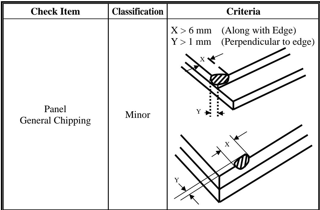
6.3.1 Cosmetic Check (Display Off) in Non-Active Area
| Check Item | Classification | Criteria |
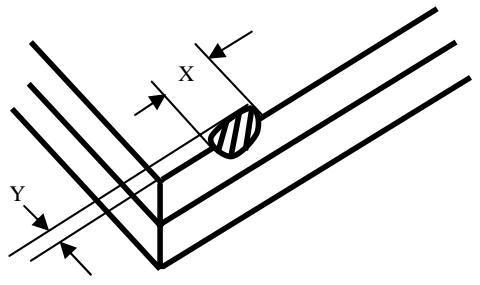
| PanelGeneral Chipping | Minor | X > 6 mm (Along with Edge)Y > 1 mm (Perpendicular to edge)<img src="./images/75ca779e3707e9d05ac0d1aba61970dafa21c82efc6fedf4e7ecc7d1613bf190.jpg"/><img src="./images/620b046a8b8d4dfdf1b5d10cc57e8e82c1e3794aa27a803d8e24b99d6f026c48.jpg"/> |
6.3.1 Cosmetic Check (Display Off) in Non-Active Area (Continued)
| Check Item | Classification | Criteria |
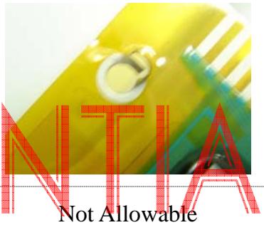
| Panel Crack | Minor | Any crack is not allowable.<img src="./images/a01afe09cc8ebc0ad991e0d9e9a3fe0ef2c12386c1a97e12742cb669aa3a43ac.jpg"/> |
| Cupper Exposed (Even Pin or Film) | Minor | Not Allowable by Naked Eye Inspection |
| Film or Trace Damage | Minor | <img src="./images/fdca3aac3df498565e389d60e5e229243971c61e8fc26eca3ff27a396ab24876.jpg"/>D. TWISTED LEAD<img src="./images/d16fb1afa90022a1628d40ef61ef81c9d4f605dd5c35716acc20e4c44a2b710d.jpg"/> |
| Terminal Lead Twist | Minor | |
| Terminal Lead Broken | Minor | Not Allowable-A. BROKEN LEAD<img src="./images/9b543356cbad3211817a2f863ccaab57788432b5585051861cfb449e2264e8d9.jpg"/> |
| Terminal Lead Prober Mark | Acceptable | <img src="./images/54a6abeeff70c0533593130f64bd36fee3fc03f979e3907d483ca304150248f8.jpg"/> |
6.3.1 Cosmetic Check (Display Off) in Non-Active Area (Continued)
| Check Item | Classification | Criteria |
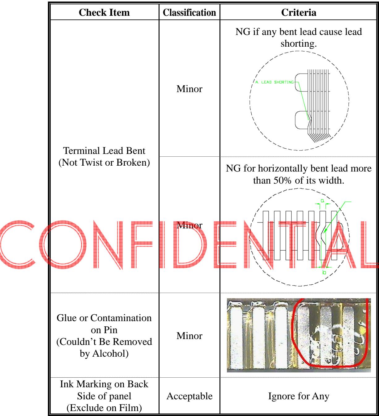
| Terminal Lead Bent(Not Twist or Broken) | Minor | NG if any bent lead cause lead shorting.<img src="./images/cc0bccd2ebfaad2bf3eb843a9fc39d0ad2e764d9d084d481162cdefcd24caf4d.jpg"/> |
| Minor | NG for horizontally bent lead more than 50% of its width.<img src="./images/90958cc34e20bb83e6cedf256d99412fc12c9e6e239364b742f7ac0c3bf8b7a6.jpg"/> | |
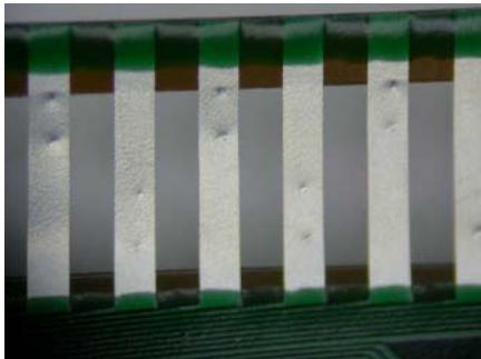
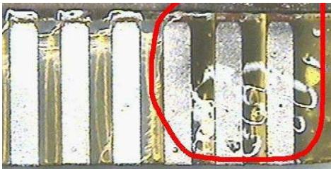
| Glue or Contamination on Pin(Couldn’t Be Removed by Alcohol) | Minor | <img src="./images/5ec7bd948f0ce964bf035c6820046bae740114cfa3520dd88d28091634c5b5bf.jpg"/> |
| Ink Marking on Back Side of panel(Exclude on Film) | Acceptable | Ignore for Any |
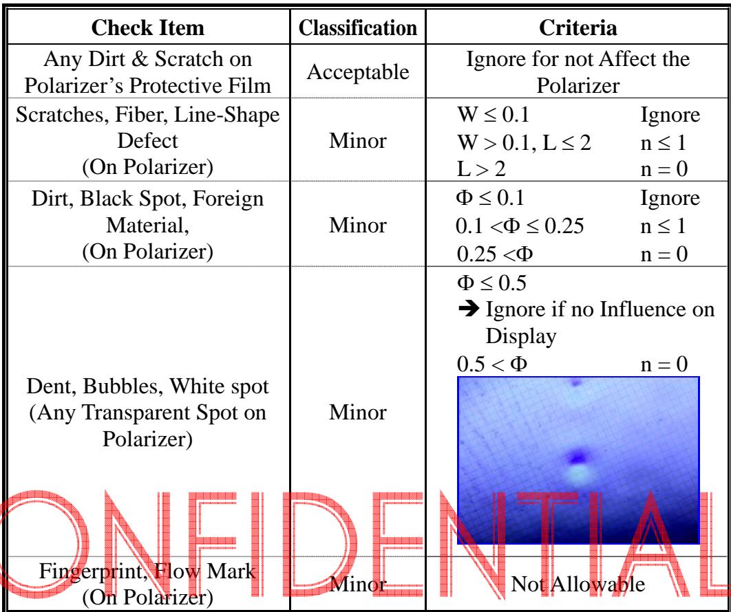
6.3.2 Cosmetic Check (Display Off) in Active Area
| Check Item | Classification | Criteria |
| Any Dirt & Scratch on Polarizer's Protective Film | Acceptable | Ignore for not Affect the Polarizer |
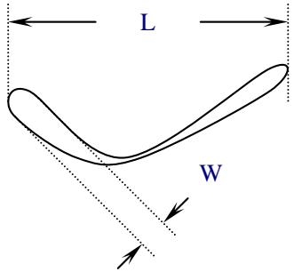
| Scratches, Fiber, Line-Shape Defect(On Polarizer) | Minor | W ≤ 0.1 Ignore W > 0.1, L ≤ 2 n ≤ 1 L > 2 n = 0 |
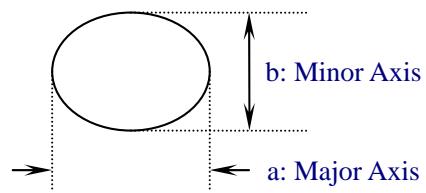
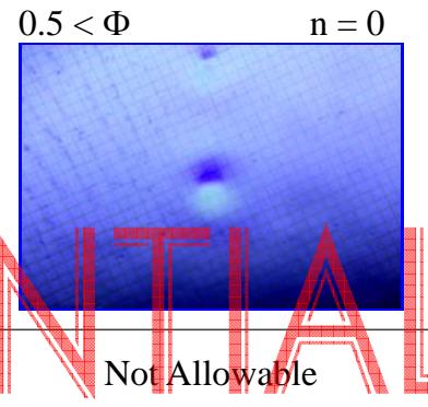
| Dirt, Black Spot, Foreign Material,(On Polarizer) | Minor | Φ ≤ 0.1 Ignore 0.1 < Φ ≤ 0.25 n ≤ 1 0.25 < Φ n = 0 |
| Dent, Bubbles, White spot (Any Transparent Spot on Polarizer) | Minor | Φ ≤ 0.5 ➔ Ignore if no Influence on Display |
| Fingerprint, Flow Mark(On Polarizer) | Minor | <img src="./images/77fe5cfe627a4e146475188226f7f38e126fa681f5096a703385088766d9b129.jpg"/> |
* Protective film should not be tear off when cosmetic check.
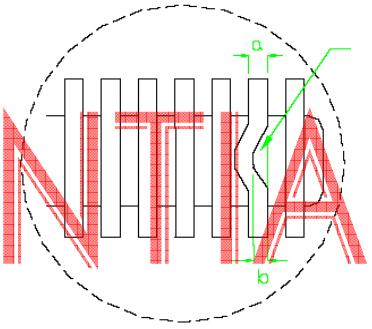
** Definition of W & L & Φ (Unit: mm): $\Phi = (a + b) / 2$
6.3.3 Pattern Check (Display On) in Active Area
| Check Item | Classification | Criteria |
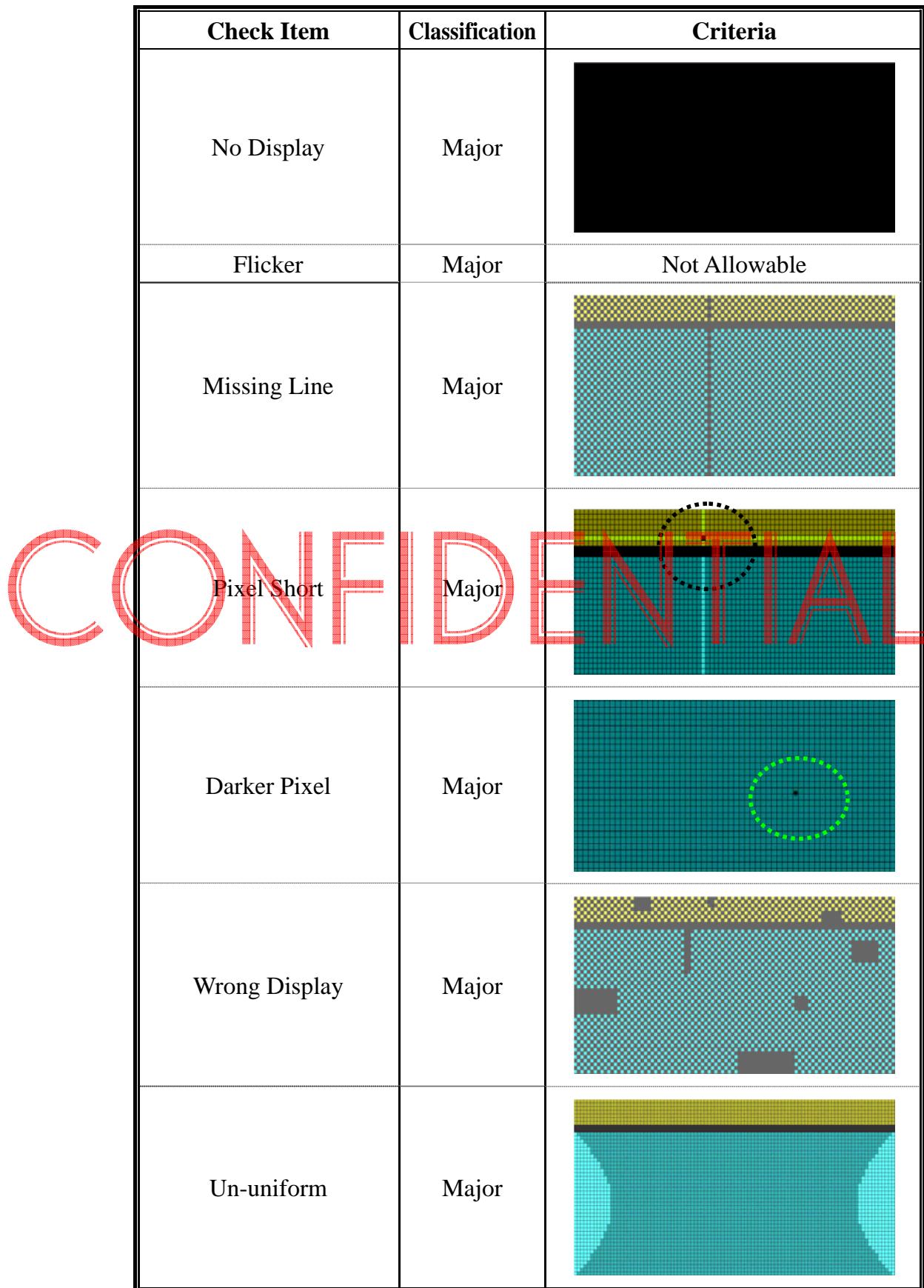
| No Display | Major | <img src="./images/24c408016c6f12aad768698b7569cab6eac8b950c0e68e13216c49dc35261dd7.jpg"/> |
| Flicker | Major | Not Allowable |
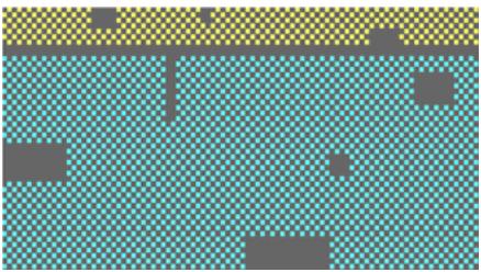
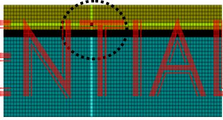
| Missing Line | Major | <img src="./images/0fde6932b694d18602ce8523155765c1392ebdd57016046e814ba44c58247849.jpg"/> |
| Pixel Short | Major | <img src="./images/1ac416c8ca24a5d22750f9fb803e909dd3dd0f9000fae9ca749ca2e70fece071.jpg"/> |
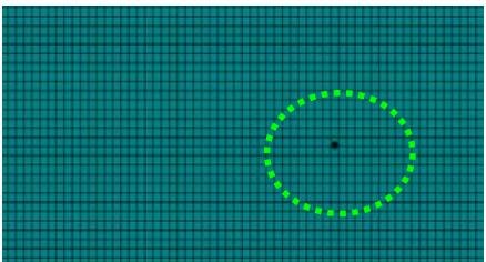
| Darker Pixel | Major | <img src="./images/fcea5c40e413e5f17a5fcbc8e451a15ccc62ac8314600cdeac0d04bf926a1c7f.jpg"/> |
| Wrong Display | Major | <img src="./images/f0e3a3d187a7d49f98223c69feb0aa999270132381019f155803c1245c0624d2.jpg"/> |
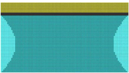
| Un-uniform | Major | <img src="./images/39742673a371762f150b929d971c15d7ceb6077b1742bce309aeb0b189f920ac.jpg"/> |
7. Package Specifications
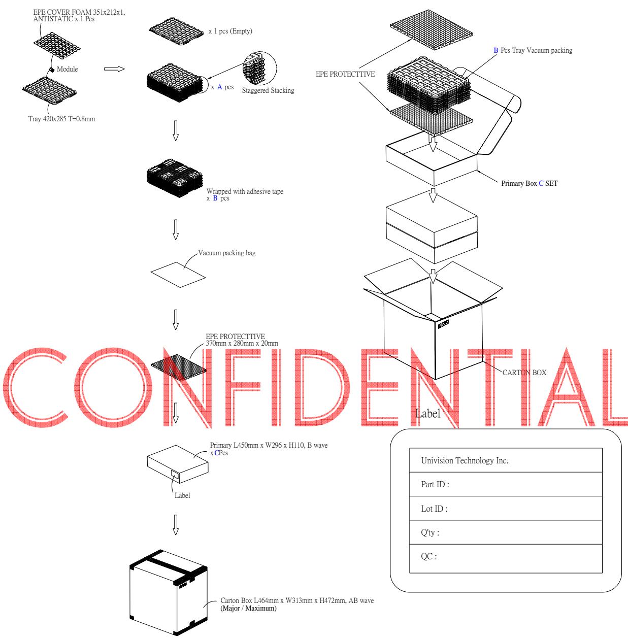
| Item | Quantity | ||
| Holding Trays | (A) | 15 | per Primary Box |
| Total Trays | (B) | 16 | per Primary Box (Including 1 Empty Tray) |
| Primary Box | (C) | 1~4 | per Carton (4 as Major / Maximum) |
8. Precautions When Using These OEL Display Modules
8.1 Handling Precautions
Since the display panel is being made of glass, do not apply mechanical impacts such us dropping from a high position.
If the display panel is broken by some accident and the internal organic substance leaks out, be careful not to inhale nor lick the organic substance.
If pressure is applied to the display surface or its neighborhood of the OEL display module, the cell structure may be damaged and be careful not to apply pressure to these sections.
The polarizer covering the surface of the OEL display module is soft and easily scratched. Please be careful when handling the OEL display module.
When the surface of the polarizer of the OEL display module has soil, clean the surface. It takes advantage of by using following adhesion tape.
* Scotch Mending Tape No. 810 or an equivalent
Never try to breathe upon the soiled surface nor wipe the surface using cloth containing solvent such as ethyl alcohol, since the surface of the polarizer will become cloudy.
Also, pay attention that the following liquid and solvent may spoil the

- Hold OEL display module very carefully when placing OEL display module into the system housing. Do not apply excessive stress or pressure to OEL display module. And, do not over bend the film with electrode pattern layouts. These stresses will influence the display performance. Also, secure sufficient rigidity for the outer cases.
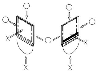
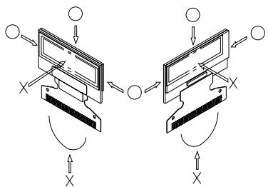
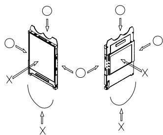
Do not apply stress to the LSI chips and the surrounding molded sections.
Do not disassemble nor modify the OEL display module.
Do not apply input signals while the logic power is off.
Pay sufficient attention to the working environments when handing OEL display modules to prevent occurrence of element breakage accidents by static electricity.
* Be sure to make human body grounding when handling OEL display modules.
* Be sure to ground tools to use or assembly such as soldering irons.
* To suppress generation of static electricity, avoid carrying out assembly work under dry environments.
* Protective film is being applied to the surface of the display panel of the OEL display module. Be careful since static electricity may be generated when exfoliating the protective film.
Protection film is being applied to the surface of the display panel and removes the protection film before assembling it. At this time, if the OEL display module has been stored for a long period of time, residue adhesive material of the protection film may remain on the surface of the display panel after removed of the film. In such case, remove the residue material by the method introduced in the above Section 5).
If electric current is applied when the OEL display module is being dewed or when it is placed under high humidity environments, the electrodes may be corroded and be careful to avoid the above.
8.2 Storage Precautions
- When storing OEL display modules, put them in static electricity preventive bags avoiding exposure to direct sun light nor to lights of fluorescent lamps, etc. and, also, avoiding high temperature and high humidity environments or low temperature (less than $0^{\circ}$ C) environments. (We recommend you to store these modules in the packaged state when they were shipped from Univision Technology Inc.)
At that time, be careful not to let water drops adhere to the packages or bags nor let dewing occur with them. If electric current is applied when water drops are adhering to the surface of the OEL display module, when the OEL display module is being dewed or when it is placed under high humidity environments, the electrodes may be corroded and be careful about the above.
8.3 Designing Precautions
The absolute maximum ratings are the ratings which cannot be exceeded for OEL display module, and if these values are exceeded, panel damage may be happen.
To prevent occurrence of malfunctioning by noise, pay attention to satisfy the VIL and VIH specifications and, at the same time, to make the signal line cable as short as possible.
We recommend you to install excess current preventive unit (fuses, etc.) to the power circuit (VDD). (Recommend value: 0.5A)
Pay sufficient attention to avoid occurrence of mutual noise interference with the neighboring devices.
As for EMI, take necessary measures on the equipment side basically.
When fastening the OEL display module, fasten the external plastic housing section.
If power supply to the OEL display module is forcibly shut down by such errors as taking out the main battery while the OEL display panel is in operation, we cannot guarantee the quality of this OEL display module.
The electric potential to be connected to the rear face of the IC chip should be as follows: SSD1306
* Connection (contact) to any other potential than the above may lead to rupture of the IC.
8.4 Precautions when disposing of the OEL display modules
- Request the qualified companies to handle industrial wastes when disposing of the OEL display modules. Or, when burning them, be sure to observe the environmental and hygienic laws and regulations.
8.5 Other Precautions
- When an OEL display module is operated for a long of time with fixed pattern may remain as an after image or slight contrast deviation may occur.
Nonetheless, if the operation is interrupted and left unused for a while, normal state can be restored. Also, there will be no problem in the reliability of the module.
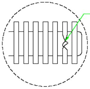
- To protect OEL display modules from performance drops by static electricity rapture, etc., do not touch the following sections whenever possible while handling the OEL display modules.
* Pins and electrodes
* Pattern layouts such as the FPC
- With this OEL display module, the OEL driver is being exposed. Generally speaking, semiconductor elements change their characteristics when light is radiated according to the principle of the solar battery. Consequently, if this OEL driver is exposed to light, malfunctioning may occur.
* Design the product and installation method so that the OEL driver may be shielded from light in actual usage.
* Design the product and installation method so that the OEL driver may be shielded from light during the inspection processes.
Although this OEL display module stores the operation state data by the commands and the indication data, when excessive external noise, etc. enters into the module, the internal status may be changed. It therefore is necessary to take appropriate measures to suppress noise generation or to protect from influences of noise on the system design.
We recommend you to construct its software to make periodical refreshment of the operation statuses (re-setting of the commands and re-transference of the display data) to cope with catastrophic noise.
Figures and diagrams from the PDF
Preview the extracted datasheet assets and open any image in a separate tab for closer inspection.




Use this datasheet from any agent
Send the page, markdown, chunks, or search endpoint to ChatGPT, Claude, embedr-app, or your own tooling.