
MAX7375AXR105
1MHz Silicon Clock Oscillator
General Description
The MAX7375 is a silicon oscillator, intended as a low-cost improvement replacing ceramic resonators, crystals, and crystal oscillator modules used as the clock source for microcontrollers and UARTs in 3V, 3.3V, and 5V applications.
The MAX7375 is a fully integrated oscillator, supplied at specific factory-trimmed frequencies with a rail-to-rail 50% duty cycle square-wave output. The oscillator frequency is generated directly without the use of a phase-locked loop (PLL). No additional components are used to set or adjust the frequency.
Unlike typical crystal and ceramic resonator oscillator circuits, the MAX7375 is highly resistant to vibration and EMI. The high output drive current and absence of high-impedance nodes also makes the oscillator less susceptible to dirty or humid operating conditions. With a wide operating temperature range, the oscillator is a good choice for demanding home appliance environments.
Available in 3-pin space-saving SC70 package, the MAX7375 is offered in standard and nonstandard factoryset frequencies ranging from 600kHz to 9.99MHz. See the MAX7381 data sheet for frequencies ≥ 10MHz. The MAX7375’s standard operating temperature range is -40°C to +125°C. See the Applications Information section for extended operating temperature range.
Applications
● White Goods
● Appliances and Controls
● Portable Equipment
● Microcontroller Systems
● Hand-Held Products
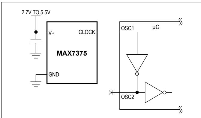
Typical Application Circuit
Features
● 2.7V to 5.5V Operation
● Factory-Trimmed Oscillator (600kHz to 9.99MHz)
● No External Components Required
● ±10mA Output Drive Current
● 2% Initial Accuracy
● ±50ppm/°C Temp Drift
● Fast Startup Time: 5µs
● 40% to 60% Maximum Duty Cycle
● 5ns Output Rise and Fall Time-Low EMI
● Very Low EMI Susceptibility-No High-Impedance Nodes
● Very Low Jitter: 160psP-P at 8MHz
● Tiny Surface-Mount Package (SC70)
● -40°C to +125°C Temperature Range
Ordering Information
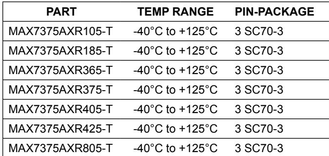
| PART | TEMP RANGE | PIN-PACKAGE |
| MAX7375AXR105-T | -40°C to +125°C | 3 SC70-3 |
| MAX7375AXR185-T | -40°C to +125°C | 3 SC70-3 |
| MAX7375AXR365-T | -40°C to +125°C | 3 SC70-3 |
| MAX7375AXR375-T | -40°C to +125°C | 3 SC70-3 |
| MAX7375AXR405-T | -40°C to +125°C | 3 SC70-3 |
| MAX7375AXR425-T | -40°C to +125°C | 3 SC70-3 |
| MAX7375AXR805-T | -40°C to +125°C | 3 SC70-3 |
Note: The MAX7375 is available in factory-set frequencies from 600kHz to 9.99MHz. There are seven standard versions (1MHz, 1.84MHz, 3.58MHz, 3.69MHz, 4MHz, 4.19MHz, and 8MHz, as shown in the Selector Guide) with a required 2.5k order increment. Nonstandard frequencies are also available with a required 10k order increment. For nonstandard versions, contact factory for availability and ordering information. All versions available in tape-and-reel only.
Pin Configuration and Selector Guide appear at end of data sheet.
Absolute Maximum Ratings
V+ to GND... ...-0.3V to +6V CLOCK to GND ....... ...-0.3V to $( \mathsf { V } + + 0 . 3 \mathsf { V } )$ Continuous Power Dissipation $( \mathsf { T } _ { \mathsf { A } } = + 7 0 ^ { \circ } \mathsf { C } )$
3-Pin SC70 (derate 2.9mW/°C over +70°C)................235mW
Operating Temperature Range.. $- 5 5 ^ { \circ } \mathsf { C } \mathsf { t o } + 1 3 5 ^ { \circ } \mathsf { C }$ Junction Temperature... .+150°C Storage Temperature Range..... .... -65°C to +150°C Lead Temperature (soldering, 10s) ... ..+300°C
Stresses beyond those listed under “Absolute Maximum Ratings” may cause permanent damage to the device. These are stress ratings only, and functional operation of the device at these or any other conditions beyond those indicated in the operational sections of the specifications is not implied. Exposure to absolute maximum rating conditions for extended periods may affect device reliability.
Electrical Characteristics
(V+ = 2.7V to 5.5V, $\mathsf { T } _ { \mathsf { A } } = - 4 0 ^ { \circ } \mathsf { C }$ to +125°C, unless otherwise noted. Typical values are at V+ = 5V, ${ \mathsf { T } } _ { \mathsf { A } } = + 2 5 ^ { \circ } { \mathsf { C } }$ , unless otherwise noted.) (Note 1)
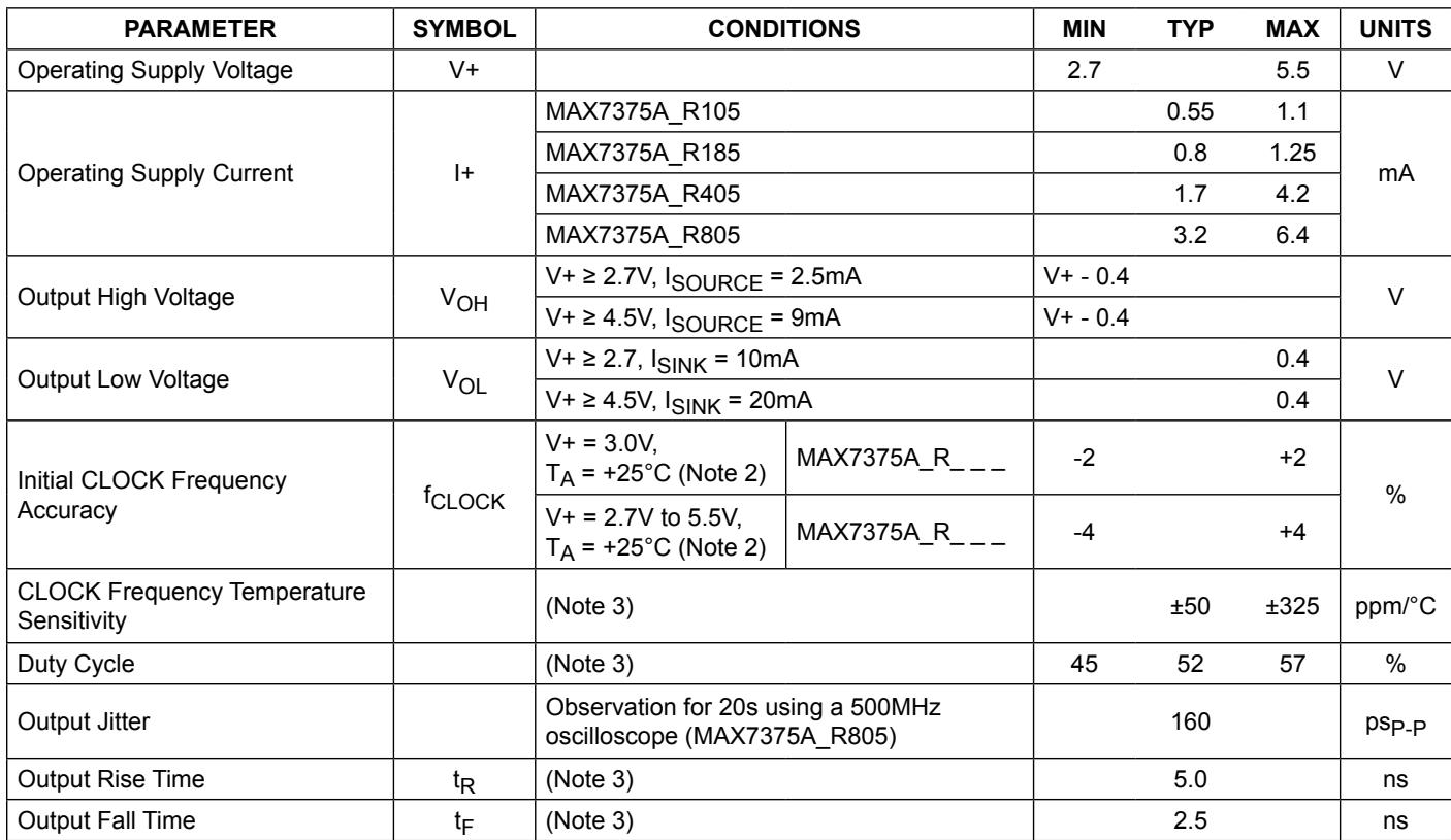
| PARAMETER | SYMBOL | CONDITIONS | MIN | TYP | MAX | UNITS | |
| Operating Supply Voltage | V+ | 2.7 | 5.5 | V | |||
| Operating Supply Current | I+ | MAX7375A_R105 | 0.55 | 1.1 | mA | ||
| MAX7375A_R185 | 0.8 | 1.25 | |||||
| MAX7375A_R405 | 1.7 | 4.2 | |||||
| MAX7375A_R805 | 3.2 | 6.4 | |||||
| Output High Voltage | VOH | V+ ≥ 2.7V, ISOURCE = 2.5mA | V+ - 0.4 | V | |||
| V+ ≥ 4.5V, ISOURCE = 9mA | V+ - 0.4 | ||||||
| Output Low Voltage | VOL | V+ ≥ 2.7, ISINK = 10mA | 0.4 | V | |||
| V+ ≥ 4.5V, ISINK = 20mA | 0.4 | ||||||
| Initial CLOCK Frequency Accuracy | fCLOCK | V+ = 3.0V, TA = +25°C (Note 2) | MAX7375A_R__ | -2 | +2 | % | |
| V+ = 2.7V to 5.5V, TA = +25°C (Note 2) | MAX7375A_R__ | -4 | +4 | ||||
| CLOCK Frequency Temperature Sensitivity | (Note 3) | ±50 | ±325 | ppm/°C | |||
| Duty Cycle | (Note 3) | 45 | 52 | 57 | % | ||
| Output Jitter | Observation for 20s using a 500MHz oscilloscope (MAX7375A_R805) | 160 | psP-P | ||||
| Output Rise Time | tR | (Note 3) | 5.0 | ns | |||
| Output Fall Time | tF | (Note 3) | 2.5 | ns | |||
Note 3: Guaranteed by design and characterization. Not production tested.
Note 1: All parameters are tested at ${ \mathsf { T } } _ { \mathsf { A } } = + 2 5 ^ { \circ } { \mathsf { C } }$ . Specifications over temperature are guaranteed by design and characterization. Note 2: Typical frequencies are nominal values.
Typical Operating Characteristics
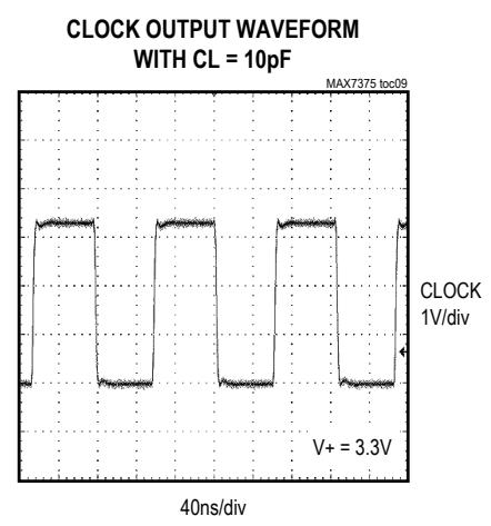
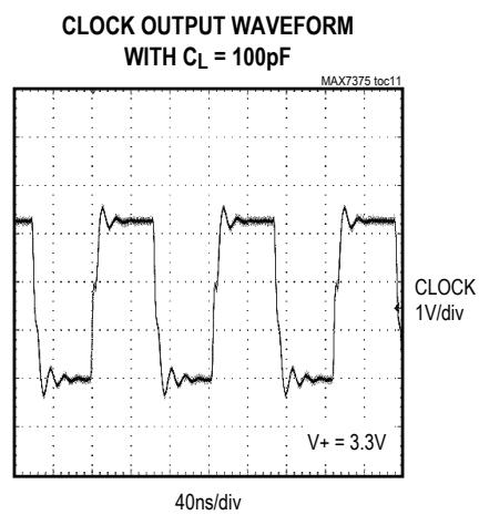
(V+ = 5V, TA = +25°C, CL = 10pF, 8MHz output, unless otherwise noted.)
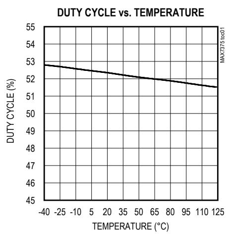
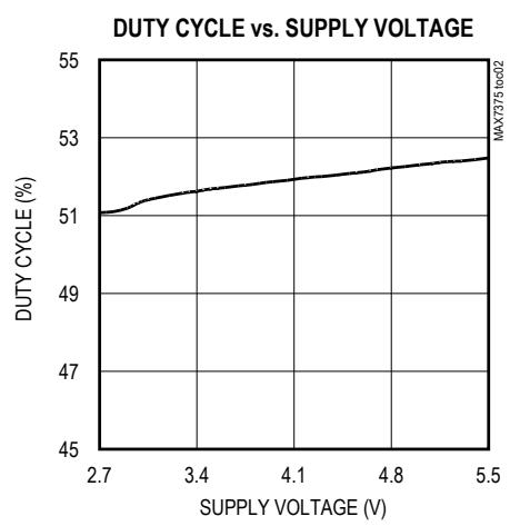
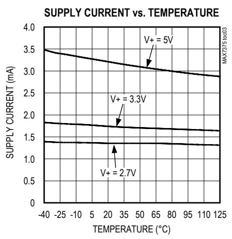
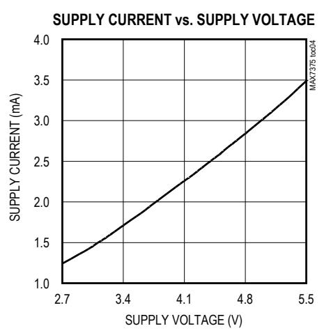
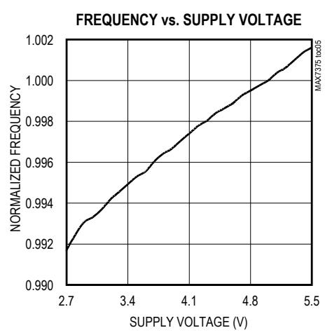
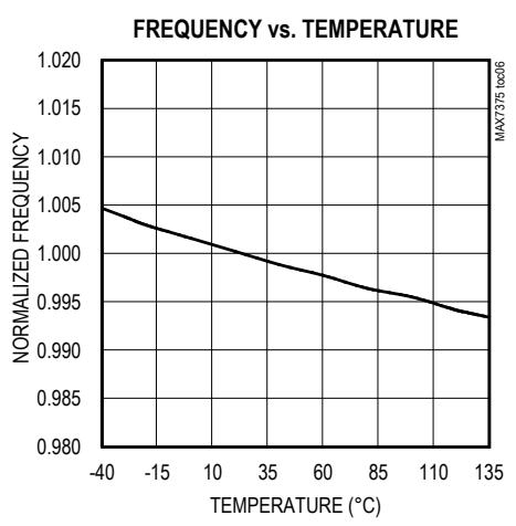
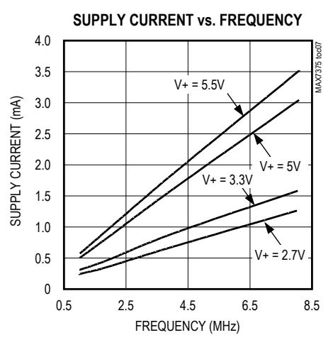
Typical Operating Characteristics (continued) (V+ = 5V, TA = +25°C, CL = 10pF, 8MHz output, unless otherwise noted.)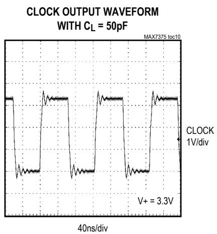
Pin Description
| PIN | NAME | FUNCTION |
| SC70 | ||
| 1 | V+ | Positive Supply Voltage |
| 2 | CLOCK | Clock Output. Output is push-pull. |
| 3 | GND | Ground |
Detailed Description
The MAX7375 is a replacement for ceramic resonators, crystals, and crystal oscillator modules as the clock source for microcontrollers and UARTs in 3V, 3.3V, and 5V applications. The MAX7375 is an integrated oscillator, supplied at specific frequencies just like crystals and resonators. A variety of popular standard frequencies are available. No external components are required for setting or adjusting the frequency.
Supply Voltages
The MAX7375 has been designed for use in systems with nominal supply voltages of 3V, 3.3V, or 5V and is specified for operation with supply voltages in the 2.7V to 5.5V range. Operation outside this range is not guaranteed. See the Absolute Maximum Ratings table for limit values of power-supply and pin voltages.
Oscillator
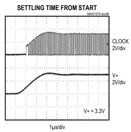
The clock output is a push-pull configuration and is capable of driving a ground-connected 1kΩ load or a positive supply connected 500Ω load to within 300mV of either supply rail. The clock output remains stable over the full operating voltage range and does not generate short output cycles during either power on or power off. A typical startup characteristic is shown in the Typical Operating Characteristics section.
Output Jitter
The MAX7375’s jitter performance is given in the Electrical Characteristics table as a peak-to-peak value obtained by observing the output of the MAX7375 for 20s with a 500MHz oscilloscope. Jitter measurements are approximately proportional to the period of the output frequency of the device. Thus, a 4MHz part has approximately twice the jitter value of an 8MHz part.
The jitter performance of all clock sources degrades in the presence of mechanical and electrical interference. The MAX7375 is relatively immune to vibration, shock, and EMI influences and thus provides a considerably more robust clock source than crystal- or ceramic-resonatorbased oscillator circuits.
Applications Information
Interfacing to a Microcontroller Clock Input
The MAX7375 clock output is a push-pull, CMOS, logic output, which directly drives any microprocessor (µP) or microcontroller (µC) clock input. There are no impedancematching issues when using the MAX7375. Operate the MAX7375 and microcontroller (or other clock input device) from the same supply voltage level. Refer to the microcontroller data sheet for clock input compatibility with external clock signals.
The MAX7375 requires no biasing components or load capacitance. When using the MAX7375 to retrofit a crystal oscillator, remove all biasing components from the oscillator input.
Startup Performance
The MAX7375 oscillator output stabilizes within a few cycles of operation after V+ rises to a sufficient voltage to start the oscillator, typically 1.65V at +25°C. Use a reset or similar voltage-detection circuit to disable devices connected to the MAX7375 until 5µs after the voltage on V+ has risen above 2.7V.
Selector Guide
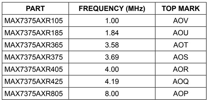
| PART | FREQUENCY (MHz) | TOP MARK |
| MAX7375AXR105 | 1.00 | AOV |
| MAX7375AXR185 | 1.84 | AOU |
| MAX7375AXR365 | 3.58 | AOT |
| MAX7375AXR375 | 3.69 | AOS |
| MAX7375AXR405 | 4.00 | AOR |
| MAX7375AXR425 | 4.19 | AOQ |
| MAX7375AXR805 | 8.00 | AOP |
Extended Temperature Operation
The MAX7375 was tested to +135°C during product characterization and shown to function normally at this temperature (see Typical Operating Characteristics). However, production test and qualification is only performed from -40°C to +125°C at this time. Contact the factory if operation outside this range is required.
Power-Supply Considerations
The MAX7375 operates with power-supply voltages in the 2.7V to 5.5V range. Good power-supply decoupling is needed to maintain the power-supply rejection performance of the MAX7375. Use a 0.1µF surface-mount ceramic capacitor connected between V+ and GND and mounted as close as possible to the device. If possible, mount the MAX7375 close to the microcontroller’s decoupling capacitor so that additional decoupling is not required.
A larger value of bypass capacitor is recommended if the MAX7375 is to operate with a large capacitive load. Use a bypass capacitor value of at least 1000 times that of the output load capacitance.
Pin Configuration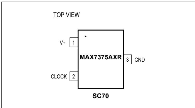
Chip Information PROCESS: BiCMOS
Package Information
For the latest package outline information and land patterns (footprints), go to www.maximintegrated.com/packages. Note that a “+”, “#”, or “-” in the package code indicates RoHS status only. Package drawings may show a different suffix character, but the drawing pertains to the package regardless of RoHS status.
| PACKAGE TYPE | PACKAGE CODE | DOCUMENT NO. | LAND PATTERN NO. |
| 3 SC70 | X3-2 | 21-0075 | 90-0208 |
Revision History
| REVISION NUMBER | REVISION DATE | DESCRIPTION | PAGES CHANGED |
| 0 | 10/03 | Initial release | — |
| 1 | — | — | — |
| 2 | — | — | — |
| 3 | 12/07 | Removed all references to MAX7375AUR_ and SOT23 package | 1, 2, 4, 5 |
| 4 | 4/14 | Removed automotive reference from General Description and Applications | 1 |
For pricing, delivery, and ordering information, please contact Maxim Direct at 1-888-629-4642, or visit Maxim Integrated’s website at www.maximintegrated.com
Maxim Integrated cannot assume responsibility for use of any circuitry other than circuitry entirely embodied in a Maxim Integrated product. No circuit patent licenses are implied. Maxim Integrated reserves the right to change the circuitry and specifications without notice at any time. The parametric values (min and max limits) shown in the Electrical Characteristics table are guaranteed. Other parametric values quoted in this data sheet are provided for guidance.
Figures and diagrams from the PDF
Preview the extracted datasheet assets and open any image in a separate tab for closer inspection.



Use this datasheet from any agent
Send the page, markdown, chunks, or search endpoint to ChatGPT, Claude, embedr-app, or your own tooling.