
MAX31826
1-Wire Digital Temperature Sensor with 1Kb Lockable EEPROM
1-Wire Digital Temperature Sensor with 1Kb Lockable EEPROM
General Description
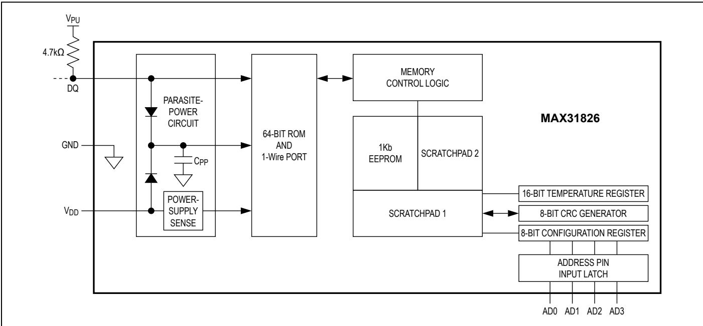
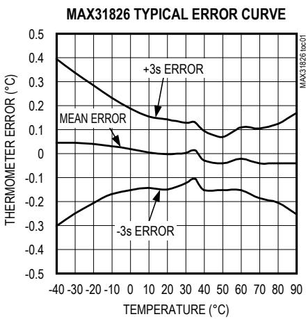
The MAX31826 digital thermometer provides 12-bit temperature measurements and communicates over a 1-Wire® bus that by definition requires only one data line (and ground) for communication with a central microcontroller. It has a - $\mathtt { - 5 5 ^ { \circ } C }$ to $+ 1 2 5 ^ { \circ } \mathrm { C }$ operating temperature range and is accurate to ±0.5°C over the -10°C to +85°C range. In addition, the device can derive power directly from the data line (“parasite power”), eliminating the need for an external power supply.
Each device has a unique 64-bit serial code, which allows multiple devices to function on the same 1-Wire bus. Therefore, it is simple to use one microcontroller (the master device) to control many devices distributed over a large area. The device includes 128 bytes (1Kb) of EEPROM for storage of system data. The EEPROM can be locked to permanently prevent any further data writes. Four location address inputs simplify mapping of individual devices to specific locations.
Applications
● Industrial Systems
● Building Automation
● System Calibration
● Module Identification
● Consumer Equipment
Benefits and Features
● Unique 1-Wire Interface Requires Only One Port Pin for Communication
● Integrated Temperature Sensor and EEPROM Reduce Component Count
• Measures Temperatures from -55°C to +125°C(-67°F to +257°F)
$\pm 0 . 5 ^ { \circ } \mathsf { C }$ Accuracy from -10°C to $+ 8 5 ^ { \circ } \mathsf { C }$
• 12-Bit Temperature Resolution (0.0625°C)
• 1Kb EEPROM Can Be Locked to Prevent Further Writes
● Multidrop Capability Simplifies Multisensor Systems
• Each Device Has a Unique 64-Bit Serial Code Stored in On-Board ROM
• Four Pin-Programmable Bits to Uniquely Identify Up to 16 Sensor Locations on a Bus
● Can Be Powered from Data Line (3.0V to 3.7V Power-Supply Range)
● 8-Pin μMAX® and TDFN Packages
Ordering Information appears at end of data sheet.
Block Diagram
1-Wire and μMAX are registered trademarks of Maxim Integrated Products, Inc.
1-Wire Digital Temperature Sensor with 1Kb Lockable EEPROM
Absolute Maximum Ratings
Voltage Range on Any Pin Relative to Ground....-0.5V to +4.5V Continuous Power Dissipation $( \mathsf { T } _ { \mathsf { A } } = + 7 0 ^ { \circ } \mathsf { C } )$
µMAX (derate 4.5mW/°C above +70°C) .....................362mW Operating Temperature Range......................... -55°C to +125°C
Storage Temperature Range.... .. -55°C to +125°C Lead Temperature (soldering, 10s) ............... ....+300°C Soldering Temperature (reflow) .... ..+260°C
Stresses beyond those listed under “Absolute Maximum Ratings” may cause permanent damage to the device. These are stress ratings only, and functional operation of the device at these or any other conditions beyond those indicated in the operational sections of the specifications is not implied. Exposure to absolute maximum rating conditions for extended periods may affect device reliability.
DC Electrical Characteristics
(TA = -55°C to +125°C, unless otherwise noted.) (Note 1)
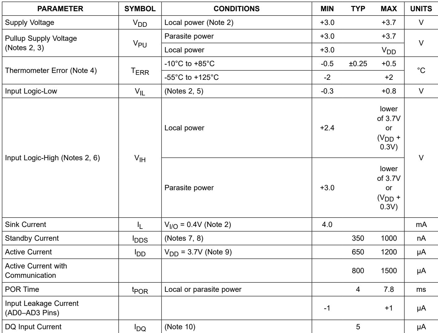
| PARAMETER | SYMBOL | CONDITIONS | MIN | TYP | MAX | UNITS |
| Supply Voltage | $V_{DD}$ | Local power (Note 2) | +3.0 | +3.7 | V | |
| Pullup Supply Voltage(Notes 2, 3) | $V_{PU}$ | Parasite power | +3.0 | +3.7 | V | |
| Local power | +3.0 | $V_{DD}$ | ||||
| Thermometer Error (Note 4) | $T_{ERR}$ | -10°C to +85°C | -0.5 | ±0.25 | +0.5 | °C |
| -55°C to +125°C | -2 | +2 | ||||
| Input Logic-Low | $V_{IL}$ | (Notes 2, 5) | -0.3 | +0.8 | V | |
| Input Logic-High (Notes 2, 6) | $V_{IH}$ | Local power | +2.4 | lower of 3.7V or $(V_{DD} + 0.3V)$ | V | |
| Parasite power | +3.0 | lower of 3.7V or $(V_{DD} + 0.3V)$ | ||||
| Sink Current | $I_L$ | $V_{I/O} = 0.4V$ (Note 2) | 4.0 | mA | ||
| Standby Current | $I_{DDS}$ | (Notes 7, 8) | 350 | 1000 | nA | |
| Active Current | $I_{DD}$ | $V_{DD} = 3.7V$ (Note 9) | 650 | 1200 | μA | |
| Active Current with Communication | 800 | 1500 | μA | |||
| POR Time | $t_{POR}$ | Local or parasite power | 4 | 7.8 | ms | |
| Input Leakage Current(AD0–AD3 Pins) | -1 | +1 | μA | |||
| DQ Input Current | $I_{DQ}$ | (Note 10) | 5 | μA |
1-Wire Digital Temperature Sensor with 1Kb Lockable EEPROM
AC Electrical Characteristics
(VDD = 3.0V to 3.7V, $\mathsf { T } _ { \mathsf { A } } = - 5 5 ^ { \circ } \mathsf { C }$ to +125°C, unless otherwise noted.) (Note 1)
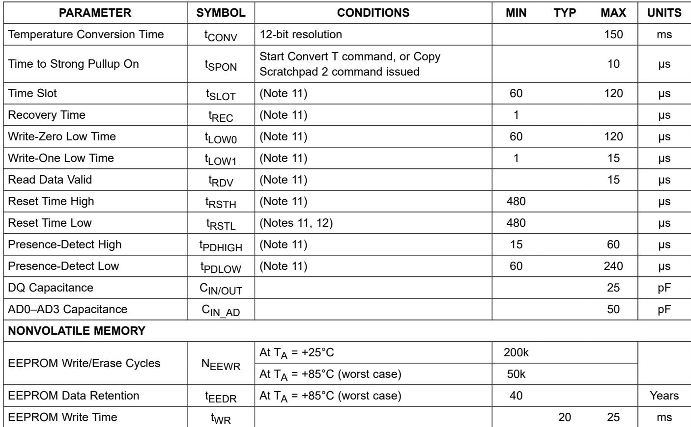
| PARAMETER | SYMBOL | CONDITIONS | MIN | TYP | MAX | UNITS |
| Temperature Conversion Time | $t_{CONV}$ | 12-bit resolution | 150 | ms | ||
| Time to Strong Pullup On | $t_{SPON}$ | Start Convert T command, or Copy Scratchpad 2 command issued | 10 | μs | ||
| Time Slot | $t_{SLOT}$ | (Note 11) | 60 | 120 | μs | |
| Recovery Time | $t_{REC}$ | (Note 11) | 1 | μs | ||
| Write-Zero Low Time | $t_{LOW0}$ | (Note 11) | 60 | 120 | μs | |
| Write-One Low Time | $t_{LOW1}$ | (Note 11) | 1 | 15 | μs | |
| Read Data Valid | $t_{RDV}$ | (Note 11) | 15 | μs | ||
| Reset Time High | $t_{RSTH}$ | (Note 11) | 480 | μs | ||
| Reset Time Low | $t_{RSTL}$ | (Notes 11, 12) | 480 | μs | ||
| Presence-Detect High | $t_{PDHIGH}$ | (Note 11) | 15 | 60 | μs | |
| Presence-Detect Low | $t_{PDLOW}$ | (Note 11) | 60 | 240 | μs | |
| DQ Capacitance | $C_{IN/OUT}$ | 25 | pF | |||
| AD0-AD3 Capacitance | $C_{IN\_AD}$ | 50 | pF | |||
| NONVOLATILE MEMORY | ||||||
| EEPROM Write/Erase Cycles | $N_{EEWR}$ | At $T_A$ =+25°C | 200k | |||
| At $T_A$ =+85°C (worst case) | 50k | |||||
| EEPROM Data Retention | $t_{EEDR}$ | At $T_A$ =+85°C (worst case) | 40 | Years | ||
| EEPROM Write Time | $t_{WR}$ | 20 | 25 | ms | ||
Note 1: Limits are 100% production tested at ${ \mathsf { T } } _ { \mathsf { A } } = + 2 5 ^ { \circ } { \mathsf { C } }$ and/or $\mathsf { T } _ { \mathsf { A } } = + 8 5 ^ { \circ } \mathsf { C }$ . Limits over the operating temperature range and relevant supply voltage range are guaranteed by design and characterization. Typical values are not guaranteed.
Note 2: All voltages are referenced to ground.
Note 3: The pullup supply voltage specification assumes that the pullup device is ideal, and therefore the high level of the pullup is equal to $\mathsf { V } _ { \mathsf { P U } } .$ . To meet the device’s $\mathsf { V } _ { \mathsf { H } }$ specification, the actual supply rail for the strong pullup transistor must include margin for the voltage drop across the transistor when it is turned on; thus: margin for the voltage drop across the transistor when it is turned on; thus: $\mathsf { V } _ { \mathsf { P U _ A C T U A L } } = \mathsf { V } _ { \mathsf { P U _ D E A L } } + \mathsf { V } _ { \mathsf { T R A N S l S T O R } } .$
Note 4: Guaranteed by design. These limits represent a three sigma distribution.
Note 5: To guarantee a presence pulse under low-voltage parasite-power conditions, VILMAX might need to be reduced to as low as 0.5V.
Note 6: Logic-high voltages are specified at a 1mA source current.
Note 7: Standby current specified up to $\mathsf { T } _ { \mathsf { A } } = + 7 0 ^ { \circ } \mathsf { C }$ . Standby current typically is 3µA at ${ \mathsf { T } } _ { \mathsf { A } } = + 1 2 5 ^ { \circ } { \mathsf { C } } .$
Note 8: To minimize IDDS, DQ should be within the following ranges: $\mathsf { V } _ { \mathsf { G N D } } \leq \mathsf { V } _ { \mathsf { D Q } } \leq \mathsf { V } _ { \mathsf { G N D } } + 0 . 3 \mathsf { V }$ or $\mathsf { V } _ { \mathsf { D } \mathsf { D } } - 0 . 3 \mathsf { V } \leq \mathsf { V } _ { \mathsf { D } \mathsf { Q } } \leq \mathsf { V } _ { \mathsf { D } \mathsf { D } }$
Note 9: Active current refers to supply current during active temperature conversions or EEPROM writes.
Note 10: DQ line is high (high-impedance state).
Note 11: See the 1-Wire Timing Diagrams.
Note 12: Under parasite power, if tRSTL > 960µs, a power-on reset (POR) can occur.
1-Wire Timing Diagrams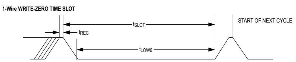
1-Wire READ-ZERO TIME SLOT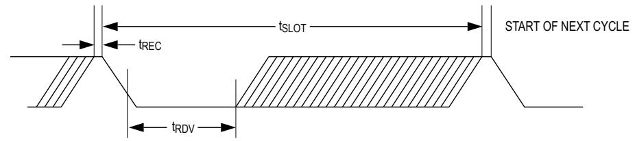
1-Wire RESET PULSE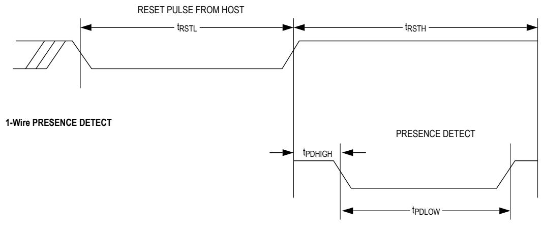
Typical Operating Characteristics (VCC = 3.3V, $\mathsf { T } _ { \mathsf { A } } = - 4 0 ^ { \circ } \mathsf { C } ,$ , unless otherwise noted.)
Pin Configuration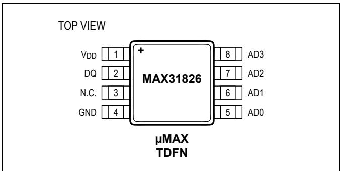
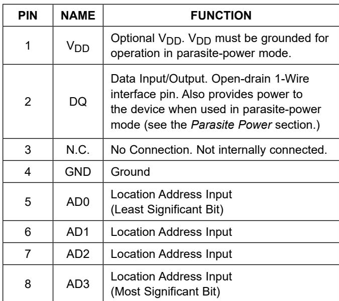
Pin Description
| PIN | NAME | FUNCTION |
| 1 | $V_{DD}$ | Optional $V_{DD}$ . $V_{DD}$ must be grounded for operation in parasite-power mode. |
| 2 | DQ | Data Input/Output. Open-drain 1-Wire interface pin. Also provides power to the device when used in parasite-power mode (see the Parasite Power section.) |
| 3 | N.C. | No Connection. Not internally connected. |
| 4 | GND | Ground |
| 5 | AD0 | Location Address Input(Least Significant Bit) |
| 6 | AD1 | Location Address Input |
| 7 | AD2 | Location Address Input |
| 8 | AD3 | Location Address Input(Most Significant Bit) |
1-Wire Digital Temperature Sensor with 1Kb Lockable EEPROM
Detailed Description
The MAX31826 digital thermometer provides 12-bit temperature measurements and communicates over a 1-Wire® bus that by definition requires only one data line (and ground) for communication with a central microcontroller. The data line requires a weak pullup resistor since all devices are linked to the bus through a three-state or open-drain port (i.e., the MAX31826’s DQ pin). Four location address inputs simplify mapping of individua devices to specific locations.
Each device has a unique 64-bit serial code, allowing multiple devices to function on the same 1-Wire bus. Therefore, it is simple to use one microcontroller to control many devices distributed over a large area. In this bus system, the microcontroller identifies and addresses devices on the bus using each device’s unique 64-bit code. Because each device has a unique code, the number of devices that can be addressed on one bus is virtually unlimited. The 1-Wire bus protocol, including detailed explanations of the commands and time slots, is described in the 1-Wire Bus System section.
The Scratchpad 1 memory contains the 2-byte temperature register that stores the digital output from the temperature sensor. An additional 128 bytes (1Kb) of general-purpose EEPROM is included for storage of system data. The EEPROM can be locked to permanently prevent any further data writes.
The device can also operate without an external power supply. Power is instead supplied through the 1-Wire pullup resistor through DQ when the bus is high. The high bus signal also charges an internal capacitor (CPP), which then supplies power to the device when the bus is low. This method of deriving power from the 1-Wire bus is referred to as parasite power. Alternatively, a power supply on VDD can also power the device.
Measuring Temperature
The device’s core functionality is its direct-to-digital temperature sensor. The resolution of the temperature sensor is 12 bits, corresponding to a least significant bit value of $0 . 0 6 2 5 ^ { \circ } \mathrm { C }$ . The device powers up in a low-power idle state. To initiate a temperature measurement, the master must issue a Convert T command. Following the conversion, the resulting thermal data is stored in the 12-bit temperature register in the Scratchpad 1 memory and the device returns to its idle state. If the device is powered by an external supply, the master can issue read time slots (see the 1-Wire Bus System section) after the Convert T command, and the device responds by transmitting 0 while the temperature conversion is in progress and 1 when the conversion is done. If the device is powered with parasite power, this notification technique cannot be used because the bus must be pulled high by a strong pullup during the entire temperature conversion. The bus requirements for parasite power are explained in the Powering the MAX31826 section.
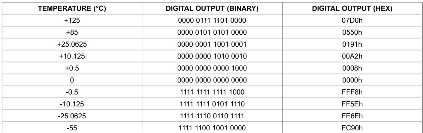
The temperature data (in °C) is stored as a 16-bit signextended two’s complement number in the temperature register (see the Temperature Register Format). The sign bits (S) indicate if the temperature is positive or negative; for positive numbers S = 0 and for negative numbers S = 1. Table 1 gives examples of digital output data and the corresponding temperature readings.
Temperature Register Format
| BIT 15 | BIT 14 | BIT 13 | BIT 12 | BIT 11 | BIT 10 | BIT 9 | BIT 8 | |
| MSB | S | S | S | S | S | $2^6$ | $2^5$ | $2^4$ |
| BIT 7 | BIT 6 | BIT 5 | BIT 4 | BIT 3 | BIT 2 | BIT 1 | BIT 0 | |
| LSB | $2^{3}$ | $2^{2}$ | $2^{1}$ | $2^{0}$ | $2^{-1}$ | $2^{-2}$ | $2^{-3}$ | $2^{-4}$ |
Table 1. Temperature/Data Relationship
| TEMPERATURE (°C) | DIGITAL OUTPUT (BINARY) | DIGITAL OUTPUT (HEX) |
| +125 | 0000 0111 1101 0000 | 07D0h |
| +85 | 0000 0101 0101 0000 | 0550h |
| +25.0625 | 0000 0001 1001 0001 | 0191h |
| +10.125 | 0000 0000 1010 0010 | 00A2h |
| +0.5 | 0000 0000 0000 1000 | 0008h |
| 0 | 0000 0000 0000 0000 | 0000h |
| -0.5 | 1111 1111 1111 1000 | FFF8h |
| -10.125 | 1111 1111 0101 1110 | FF5Eh |
| -25.0625 | 1111 1110 0110 1111 | FE6Fh |
| -55 | 1111 1100 1001 0000 | FC90h |
Powering the MAX31826
The MAX31826 can be powered by an external supply on the VDD pin, or it can operate in “parasite power” mode, which allows the device to function without a local external supply. Parasite power is useful for applications that require remote temperature sensing or those that are very space-constrained. Figure 1 shows the device’s parasite-power control circuitry, which “steals” power from the 1-Wire bus through DQ when the bus is high. The stolen charge powers the device while the bus is high, and some of the charge is stored on the parasite-power capacitor (CPP) to provide power when the bus is low. When the device is used in parasite-power mode, VDD must be connected to ground.
In parasite-power mode, the 1-Wire bus and CPP can provide sufficient current to the device for most operations as long as the specified timing and voltage requirements are met (see the DC Electrical Characteristics and the AC Electrical Characteristics tables). However, when the device is performing temperature conversions or copying data from the Scratchpad 2 memory to EEPROM, the operating current can be as high as 1.5mA. This current can cause an unacceptable voltage drop across the weak 1-Wire pullup resistor and is more current than can be supplied by CPP. To ensure that the device has sufficient supply current, it is necessary to provide a strong pullup on the 1-Wire bus whenever temperature conversions are taking place or when data is being copied from the Scratchpad 2 to EEPROM. This can be accomplished by using a MOSFET to pull the bus directly to the rail as shown in Figure 1. The 1-Wire bus must be switched to the strong pullup within 10µs (max) after a Convert T or Copy Scratchpad 2 command is issued, and the bus must be held high by the pullup for the duration of the conversion (tCONV) or the duration of the EEPROM write (tWR). No other activity can take place on the 1-Wire bus while the pullup is enabled.
The device can also be powered by the conventional method of connecting an external power supply to VDD, as shown in Figure 2. The advantage of this method is that the MOSFET pullup is not required, and the 1-Wire bus is free to carry other traffic during the temperature conversion period or EEPROM write time.
The use of parasite power is not recommended for temperatures above 100°C because the device may not be able to sustain communications due to the higher leakage currents that can exist at these temperatures. For applications in which such temperatures are likely, it is strongly recommended that the device be powered by an external power supply.
In some situations the bus master might not know whether the devices on the bus are parasite powered or powered by external supplies. The master needs this information to determine if the strong bus pullup should be used during temperature conversions. To get this information, the master can issue a Skip ROM command, followed by a Read Power Supply command, followed by a read time slot. During the read time slot, parasite-powered devices pull the bus low, and externally powered devices let the bus remain high. If the bus is pulled low, the master knows that it must supply the strong pullup on the 1-Wire bus during temperature conversions or EEPROM writes.
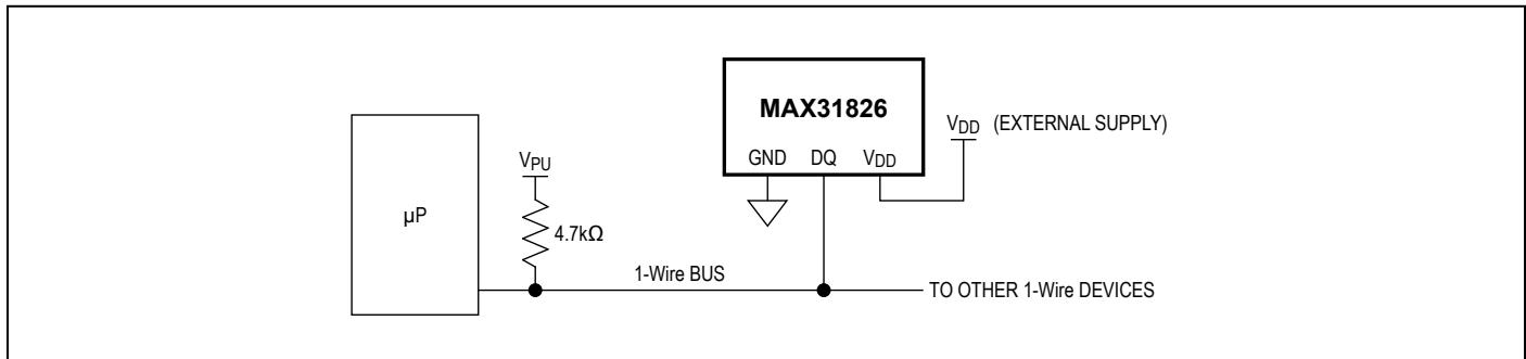
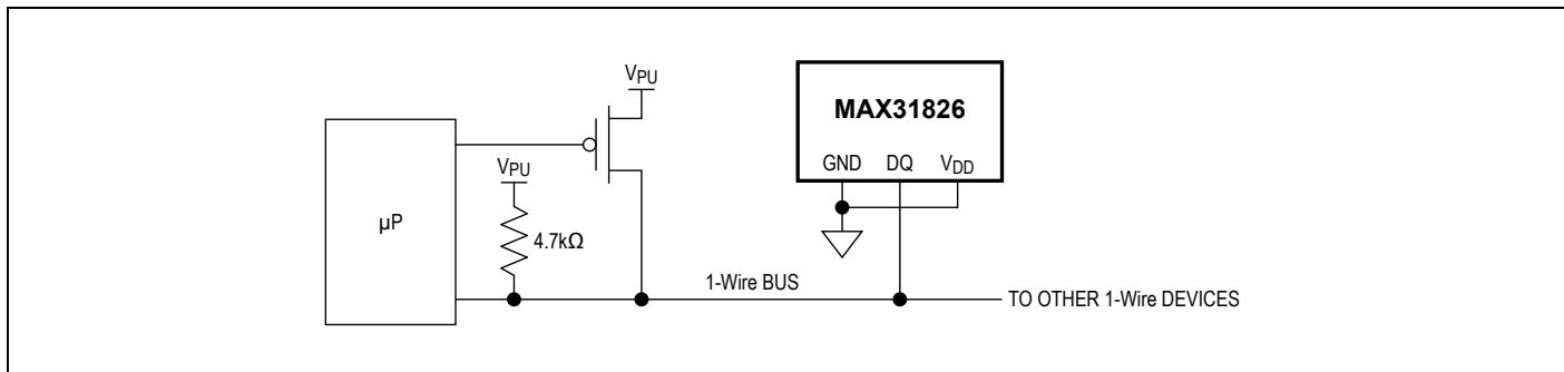
Figure 1. Supplying the Parasite-Powered MAX31826 During Temperature Conversions
Figure 2. Powering the MAX31826 with an External Supply
| MSb | LSb | |||
| 8-BITCRC CODE | 48-BIT SERIAL NUMBER | 8-BIT FAMILY CODE(3Bh) | ||
| MSb | LSb | MSb | LSb | MSb |
Figure 3. 64-Bit ROM Code
64-Bit ROM Code
Each device contains a unique 64-bit code stored in ROM (Figure 3). The least significant 8 bits of the ROM code contain the device’s 1-Wire family code, 3Bh. The next 48 bits contain a unique serial number. The most significant 8 bits contain a cyclic redundancy check (CRC) byte that is calculated from the first 56 bits of the ROM code. See the CRC Generation section for a detailed explanation of the CRC bits. The 64-bit ROM code and associated ROM function control logic allow the device to operate as a 1-Wire device using the protocol detailed in the 1-Wire Bus System section.
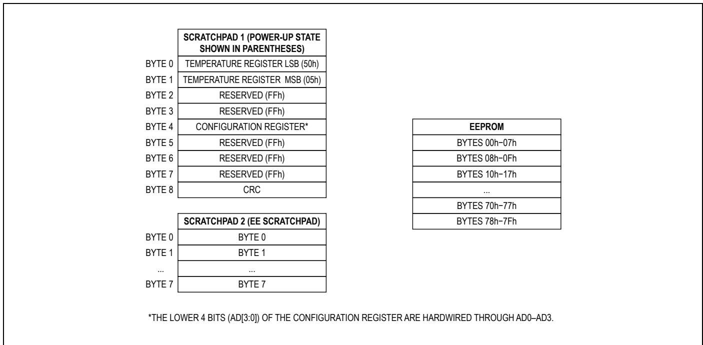
Figure 4. Memory Map
Memory
The device’s memory is organized as shown in Figure 4. The memory consists of two SRAM scratchpads (Scratchpad 1 and Scratchpad 2) and 1Kb of EEPROM, which can serve as general-purpose nonvolatile memory until locked. All memory commands are described in detail in the MAX31826 Function Commands section.
Byte 0 and byte 1 of Scratchpad 1 contain the least significant byte and the most significant byte of the temperature register, respectively. Byte 4 contains the configuration information. Bytes 2, 3, 5, 6, and 7 are reserved for internal use by the device and cannot be overwritten; these bytes return all ones when read.
Byte 8 of Scratchpad 1 is read-only and contains the CRC code for bytes 0–7 of the scratchpad. The device generates this CRC using the method described in the CRC Generation section.
Scratchpad 2 (the EE scratchpad) is used for writing to the EEPROM. Scratchpad 2 consists of 8 bytes; write data to Scratchpad 2 before copying it to the EEPROM.
Configuration Register
Byte 4 of Scratchpad 1 contains the configuration register, which is organized as shown in Configuration Register Format. The configuration register allows the user to read the programmed value of the address pins. The AD[3:0] bits report the pin-programmed location information. Pins connected to DQ (in parasite power) or VDD (when externally powered) are reported with logic 1, and pins connected to GND are reported as logic 0. Pins connected to DQ (in parasite power), VDD (when externally powered), or GND through a resistor are valid logic 1s or logic 0s if the resistor is less than 10kΩ. Unconnected or highimpedance ( > 10kΩ) connections are indeterminate. Bits [7:4] are reserved for internal use and cannot be overwritten; they return a 1 when read.
Configuration Register Format
| BIT 7 | BIT 6 | BIT 5 | BIT 4 | BIT 3 | BIT 2 | BIT 1 | BIT 0 |
| — | — | — | — | AD3 | AD2 | AD1 | AD0 |
Note: Bits [3:0] are programmed through the four location programming address pins, AD3–AD0. Reading the configuration register provides location information on up to 16 individual devices.
1-Wire Digital Temperature Sensor with 1Kb Lockable EEPROM
CRC Generation
CRC bytes are provided as part of the device’s 64-bit ROM code, in the 9th byte of Scratchpad 1, and for Scratchpad 2 values. The ROM code CRC is calculated from the first 56 bits of the ROM code and is contained in the most significant byte of the ROM. The two scratchpad CRCs are calculated from the data in each scratchpad, and therefore changes when the data in it associated scratchpad changes. The CRCs provide the bus master with a method of data validation when data is read from the device. To verify that data has been read correctly, the bus master must recalculate the CRC from the received data and then compare this value to either the ROM code CRC (for ROM reads) or to the scratchpads’ CRC (for scratchpad reads). If the calculated CRC matches the read CRC, the data has been received error-free. The comparison of CRC values and the decision to continue with an operation are determined entirely by the bus master. There is no circuitry inside the device that prevents a command sequence from proceeding if the device CRC (ROM or scratchpad) does not match the value generated by the bus master.
The equivalent polynomial function of the CRC (ROM or scratchpad) is:
$$
\mathrm{CRC} = \mathrm{X} ^ {8} + \mathrm{X} ^ {5} + \mathrm{X} ^ {4} + 1
$$
The bus master can recalculate the CRC and compare it to the CRC values from the device using the polynomial generator shown in Figure 5. This circuit consists of a shift register and XOR gates, and the shift register bits are initialized to 0. Starting with the least significant bit of the ROM code or the least significant bit of byte 0 in the scratchpad, one bit at a time should shifted into the shift register. After shifting in the 56th bit from the ROM or the most significant bit of byte 7 from the Scratchpad 1 or byte 10 from Scratchpad 2, the polynomial generator contains the recalculated CRC. Next, the 8-bit ROM code or scratchpad CRC from the device must be shifted into the circuit. At this point, if the recalculated CRC was correct, the shift register contains all zeros. Additional information about the Maxim 1-Wire CRC is available in Application Note 27: Understanding and Using Cyclic Redundancy Checks with Maxim iButton® Products.
1-Wire Bus System
The 1-Wire bus system uses a single bus master to control one or more slave devices. The MAX31826 is always a slave. When there is only one slave on the bus, the system is referred to as a single-drop system; the system is multidrop if there are multiple slaves on the bus. All data and commands are transmitted least significant bit first over the 1-Wire bus.
The following discussion of the 1-Wire bus system is broken down into three topics: hardware configuration, transaction sequence, and 1-Wire signaling (signal types and timing).
Hardware Configuration
The 1-Wire bus has by definition only a single data line. Each device (master or slave) interfaces to the data line by using an open-drain or three-state port. This allows each device to “release” the data line when the device is not transmitting data so the bus is available for use by another device. The device’s 1-Wire port (DQ) is open drain with an internal circuit equivalent to that shown in Figure 6.
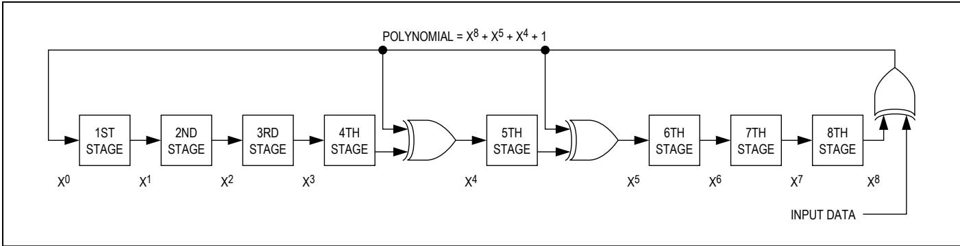
Figure 5. CRC Generator
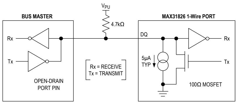
Figure 6. Hardware Configuration
The 1-Wire bus requires an external pullup resistor of approximately 5kΩ; thus, the idle state for the 1-Wire bus is high. If for any reason a transaction needs to be suspended, the bus must be left in the idle state if the transaction is to resume. Infinite recovery time can occur between bits so long as the 1-Wire bus is in the inactive (high) state during the recovery period. If the bus is held low for more than 480µs, all components on the bus are reset.
Transaction Sequence
The transaction sequence for accessing the device is as follows:
Step 1: Initialization
Step 2: ROM Command (followed by any required data exchange)
Step 3: MAX31826 Function Command (followed by any required data exchange)
It is very important to follow this sequence every time the device is accessed, as the device does not respond if any steps in the sequence are missing or out of order. An exception to this rule is the Search ROM command. After issuing this ROM command, the master must return to step 1 in the sequence.
Initialization
All transactions on the 1-Wire bus begin with an initialization sequence. The initialization sequence consists of a reset pulse transmitted by the bus master followed by presence pulse(s) transmitted by the slave(s). The presence pulse lets the bus master know that slave devices (such as the MAX31826) are on the bus and are ready to operate. Timing for the reset and presence pulses is detailed in the 1-Wire Signaling section.
ROM Commands
After the bus master has detected a presence pulse, it can issue a ROM command. These commands operate on the unique 64-bit ROM codes of each slave device and allow the master to single out a specific device if many are present on the 1-Wire bus. These commands also allow the master to determine how many and what types of devices are present on the bus. There are four ROM commands, and each command is 8 bits long. The master device must issue an appropriate ROM command before issuing a MAX31826 function command. Figure 7 shows a flowchart for operation of the ROM commands.
Search ROM [F0h]
When a system is initially powered up, the master must identify the ROM codes of all slave devices on the bus, which allows the master to determine the number of slaves and their device types. The master learns the ROM codes through a process of elimination that requires the master to perform a Search ROM cycle (i.e., Search ROM command followed by data exchange) as many times as necessary to identify all the slave devices. If there is only one slave on the bus, the simpler Read ROM command can be used in place of the Search ROM process. For a detailed explanation of the Search ROM command procedure, refer to Application Note 937: Book of iButton® Standards. After every Search ROM cycle, the bus master must return to step 1 (initialization) in the transaction sequence.
1-Wire Digital Temperature Sensor with 1Kb Lockable EEPROM
Read ROM [33h]
This command can be used only when there is one slave on the bus. It allows the bus master to read the slave’s 64-bit ROM code without using the Search ROM command procedure. If this command is used when there is more than one slave present on the bus, a data collision occurs when all the slaves attempt to respond at the same time.
Match ROM [55h]
The Match ROM command followed by a 64-bit ROM code sequence allows the bus master to address a specific slave device on a multidrop or single-drop bus. Only the slave that exactly matches the 64-bit ROM code sequence responds to the function command issued by the master; all other slaves on the bus wait for a reset pulse.
Skip ROM [CCh]
The master can use this command to address all devices on the bus simultaneously without sending out any ROM code information. For example, the master can make all devices on the bus perform simultaneous temperature conversions by issuing a Skip ROM command followed by a Convert T function command.
Note that the Read Scratchpad 1 command can follow the Skip ROM command only if there is a single slave device on the bus. In this case, time is saved by allowing the master to read from the slave without sending the device’s 64-bit ROM code. A Skip ROM command followed by a Read Scratchpad 1 command causes a data collision on the bus if there is more than one slave because multiple devices attempt to transmit data simultaneously.
MAX31826 Function Commands
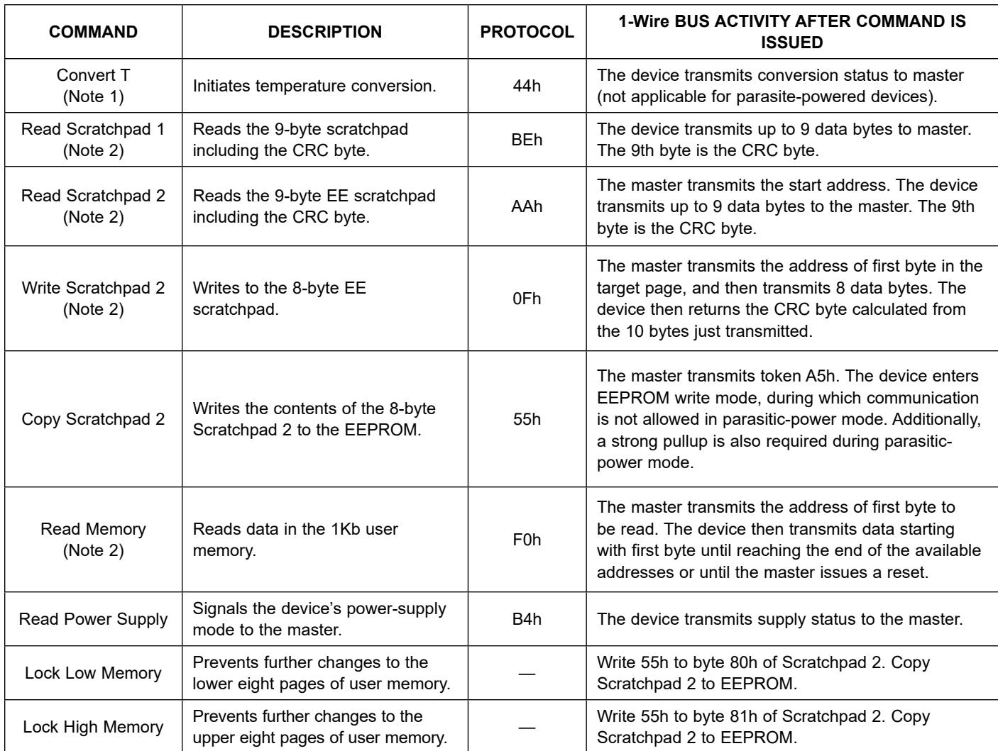
After the bus master has used a ROM command to address the MAX31826 with which it wishes to communicate, the master can issue one of the MAX31826 function commands. These commands allow the master to read from the device’s scratchpad memories, initiate temperature conversions, and determine the power-supply mode. The MAX31826 function commands are summarized in Table 2 and illustrated by the flowchart in Figure 8.
Convert T [44h]
This command initiates a single temperature conversion. Following the conversion, the resulting therma data is stored in the 2-byte temperature register in the Scratchpad 1 memory and the device returns to its lowpower idle state. If the device is being used in parasitepower mode, within 10µs (max) after this command is issued, the master must enable a strong pullup on the 1-Wire bus for the duration of the conversion (tCONV) as described in the Powering the MAX31826 section. If the device is powered by an external supply, the master can issue read time slots after the Convert T command, and the device responds by transmitting 0 while the temperature conversion is in progress and 1 when the conversion is done. In parasite-power mode, this notification technique cannot be used because the bus is pulled high by the strong pullup during the conversion.
Read Scratchpad 1 [BEh]
This command allows the master to read the contents of Scratchpad 1. The data transfer starts with the least significant bit of byte 0 and continues through the scratchpad until the 9th byte (byte 8, CRC) is read. The master can issue a reset to terminate reading at any time if only part of the scratchpad data is needed. The CRC is computed while data is read from bytes 0–7, and is shifted out as byte 8.
Read Scratchpad 2 [AAh]
This command allows the master to read the contents of Scratchpad 2. The command must be issued followed by the start address to initiate a data transfer. The data transfer always starts with the least significant bit of the byte pointed to by the address bits [2:0], and the data transfer continues through the scratchpad until 8 bytes have been read. The [2:0] address bits wrap when address [2:0] = 0x7 to [2:0] = 0x0. The master can issue a reset to terminate reading at any time if only part of the scratchpad data is needed. The CRC is computed dynamically and includes the command, address, and all the data bytes 0–7 for a total of 10 bytes. The computed CRC is shifted out at the end of data byte 7. Because the CRC contains the start address, the CRC value computed can vary with different start addresses.
Note: After the Read Scratchpad 2 command, an address of 00h returns the scratchpad contents correctly. This is true regardless of the address sent during a preceding Write Scratchpad 2 command transaction. However, the address used during a preceding Write Scratchpad 2 command is necessary here to ensure that future Copy Scratchpad 2 commands are copied to the correct row. If 00h is used instead, a future Copy Scratchpad 2 command copies the contents to address 00h as opposed to the row addressed by the Write Scratchpad 2 command.
1-Wire Digital Temperature Sensor with 1Kb Lockable EEPROM
Write Scratchpad 2 [0Fh]
This command allows the master to write 8 bytes to the EE scratchpad. After issuing the Write Scratchpad 2 command, the master must first provide the 1-byte address for the first byte of the target EEPROM page, followed by the 8 bytes of data to be written to the scratchpad for the EEPROM. The three lower bits [2:0] of the target address byte must be set to 0. The device automatically increments the address after every byte it receives. The device computes the CRC of the received data, including the command (0Fh), the target address byte, and the 8 data bytes. After having received a data byte for address 07h, the device shifts out (back to the master) the computed CRC of the 10-byte stream just received, allowing the master to verify that the data was received correctly. Note that, because the device switches direction from receive to transmit, writes to Scratchpad 2 must start with address bits [2:0] set to 0 and proceed from 0h–7h and not beyond.
Copy Scratchpad 2 [55h]
This command allows the master to copy the contents of an 8-byte page of data from Scratchpad 2 to the 1Kb user memory. The command is followed by the byte A5h. After the master writes A5h, the device enters the programming cycle, saving the data to nonvolatile memory, and does not respond to further communication for the duration of the EEPROM write time (tWR). During nonparasitic-power mode, communication with other devices can continue. If the device is being used in parasite-power mode, within 10µs (max) after A5h is issued, the master must enable a strong pullup on the 1-Wire bus for the duration of the EEPROM write time (tWR) as described in the Powering the MAX31826 section. No other activity can take place on the 1-Wire bus while the strong pullup is enabled.
Changing only 1 byte of EEPROM is not natively supported on the device. To achieve this, the master must first read the 8-byte block that contains the single byte to be changed, and the three lower bits [2:0] of the target address byte must be 0. The master must then modify the single byte and write back the 8 bytes with Write Scratchpad 2 and the same target address. Finally, the master must issue a Copy Scratchpad 2 command.
Note: The Copy Scratchpad 2 command uses the more recent of the two 8-bit addresses provided by either the Write Scratchpad 2 or Read Scratchpad 2 commands as the EEPROM destination address. The recommended procedure for writing to EEPROM starting at address 08h is as follows:
Write Scratchpad 2 (address = 08h, 8 data bytes).
Read Scratchpad 2 (address = 08h, 8 data bytes). This reads the data correctly as expected.
Copy Scratchpad 2 (0xA5).
Data is copied to row 1, which is the correct destination based on the Write Scratchpad 2 address.
Read Memory [F0h]
This command allows the master to read the contents of the 1Kb memory. The command is followed by the address of the first byte to be read (00h–7Fh). The data transfer starts with the least significant bit of the first byte and continues through 7Fh. The master can issue a reset to terminate reading at any time.
Read Power Supply [B4h]
The master device issues this command followed by a read time slot to determine if any devices on the bus are using parasite power. During the read time slot, parasite-powered devices pull the bus low, and externally powered devices do not pull the bus low. See the Powering the MAX31826 section for more information.
Lock Low Memory and Lock High Memory
The Lock Low Memory and Lock High Memory routines each lock the contents of eight pages of memory.
Lock Low Memory (bytes 00h–3Fh) as follows:
Initialize communication by issuing a reset and a ROM command.
Send Write Scratchpad 2 command.
Send address 80h as the target address to be written.
Send data 55h.
Initialize and send Copy Scratchpad 2 command.
Issue write token A5h and wait tWR.
Locations 00–3Fh are now locked. Also, location 80h is locked with value 55h. Location 80h cannot be changed to alter the lock status of 00h–3Fh.
Lock High Memory (bytes 40h–7Fh) as follows:
Initialize communication by issuing a reset and a ROM command.
Send Write Scratchpad 2 command.
Send address 81h as the target address to be written.
Send data 55h.
Initialize and send Copy Scratchpad 2 command.
Issue write token A5h and wait tWR.
1-Wire Digital Temperature Sensor with 1Kb Lockable EEPROM
Table 2. MAX31826 Function Command Set
| COMMAND | DESCRIPTION | PROTOCOL | 1-Wire BUS ACTIVITY AFTER COMMAND IS ISSUED |
| Convert T (Note 1) | Initiates temperature conversion. | 44h | The device transmits conversion status to master (not applicable for parasite-powered devices). |
| Read Scratchpad 1 (Note 2) | Reads the 9-byte scratchpad including the CRC byte. | BEh | The device transmits up to 9 data bytes to master. The 9th byte is the CRC byte. |
| Read Scratchpad 2 (Note 2) | Reads the 9-byte EE scratchpad including the CRC byte. | AAh | The master transmits the start address. The device transmits up to 9 data bytes to the master. The 9th byte is the CRC byte. |
| Write Scratchpad 2 (Note 2) | Writes to the 8-byte EE scratchpad. | 0Fh | The master transmits the address of first byte in the target page, and then transmits 8 data bytes. The device then returns the CRC byte calculated from the 10 bytes just transmitted. |
| Copy Scratchpad 2 | Writes the contents of the 8-byte Scratchpad 2 to the EEPROM. | 55h | The master transmits token A5h. The device enters EEPROM write mode, during which communication is not allowed in parasitic-power mode. Additionally, a strong pullup is also required during parasitic-power mode. |
| Read Memory (Note 2) | Reads data in the 1Kb user memory. | F0h | The master transmits the address of first byte to be read. The device then transmits data starting with first byte until reaching the end of the available addresses or until the master issues a reset. |
| Read Power Supply | Signals the device's power-supply mode to the master. | B4h | The device transmits supply status to the master. |
| Lock Low Memory | Prevents further changes to the lower eight pages of user memory. | — | Write 55h to byte 80h of Scratchpad 2. Copy Scratchpad 2 to EEPROM. |
| Lock High Memory | Prevents further changes to the upper eight pages of user memory. | — | Write 55h to byte 81h of Scratchpad 2. Copy Scratchpad 2 to EEPROM. |
Note 1: For parasite-powered devices, the master must enable a strong pullup on the 1-Wire bus during temperature conversions and copies from the Scratchpad 2 to EEPROM. No other bus activity can take place during this time. Note 2: The master can interrupt the transmission of data at any time by issuing a reset.
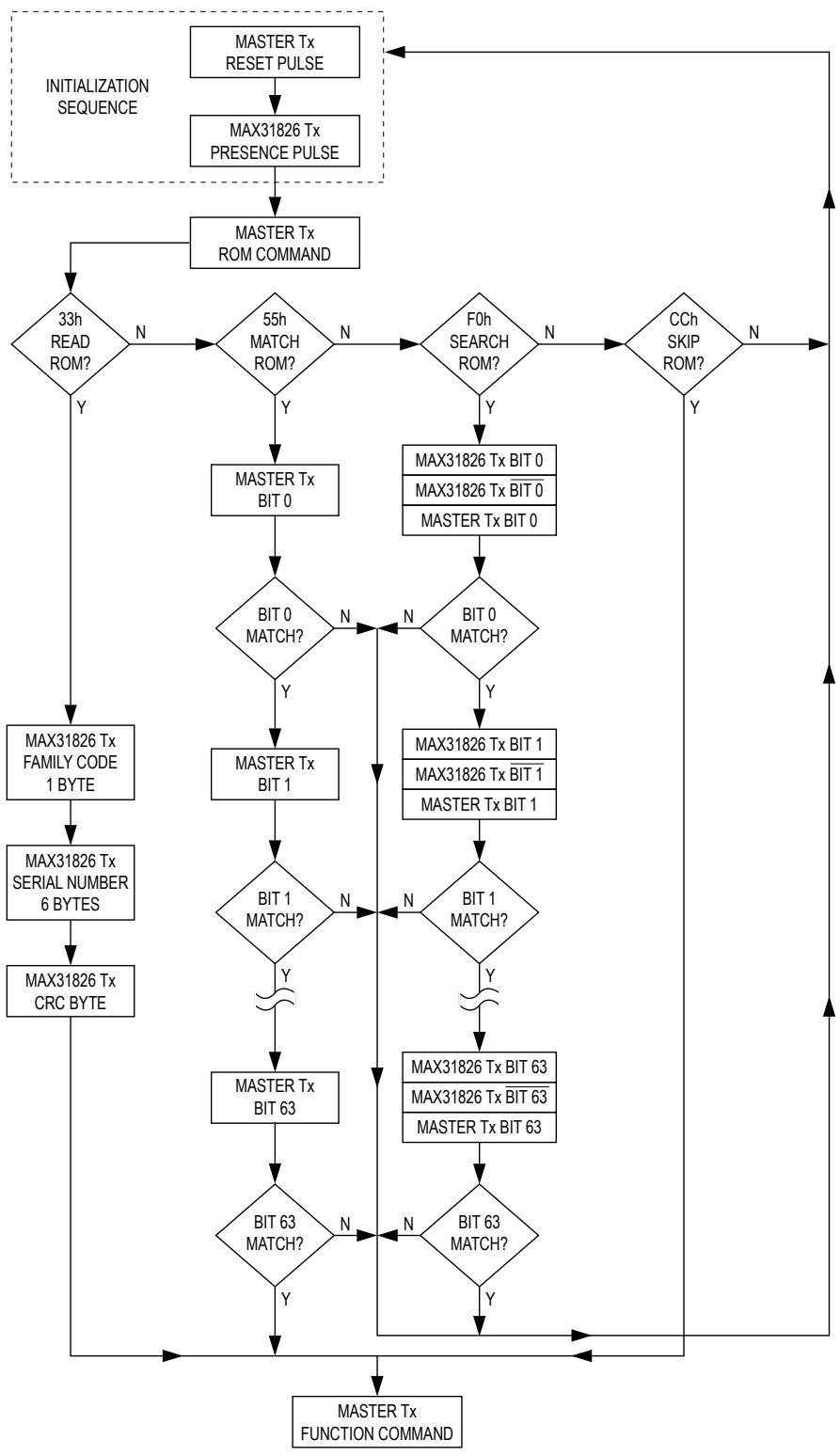
Figure 7. ROM Commands Flowchart
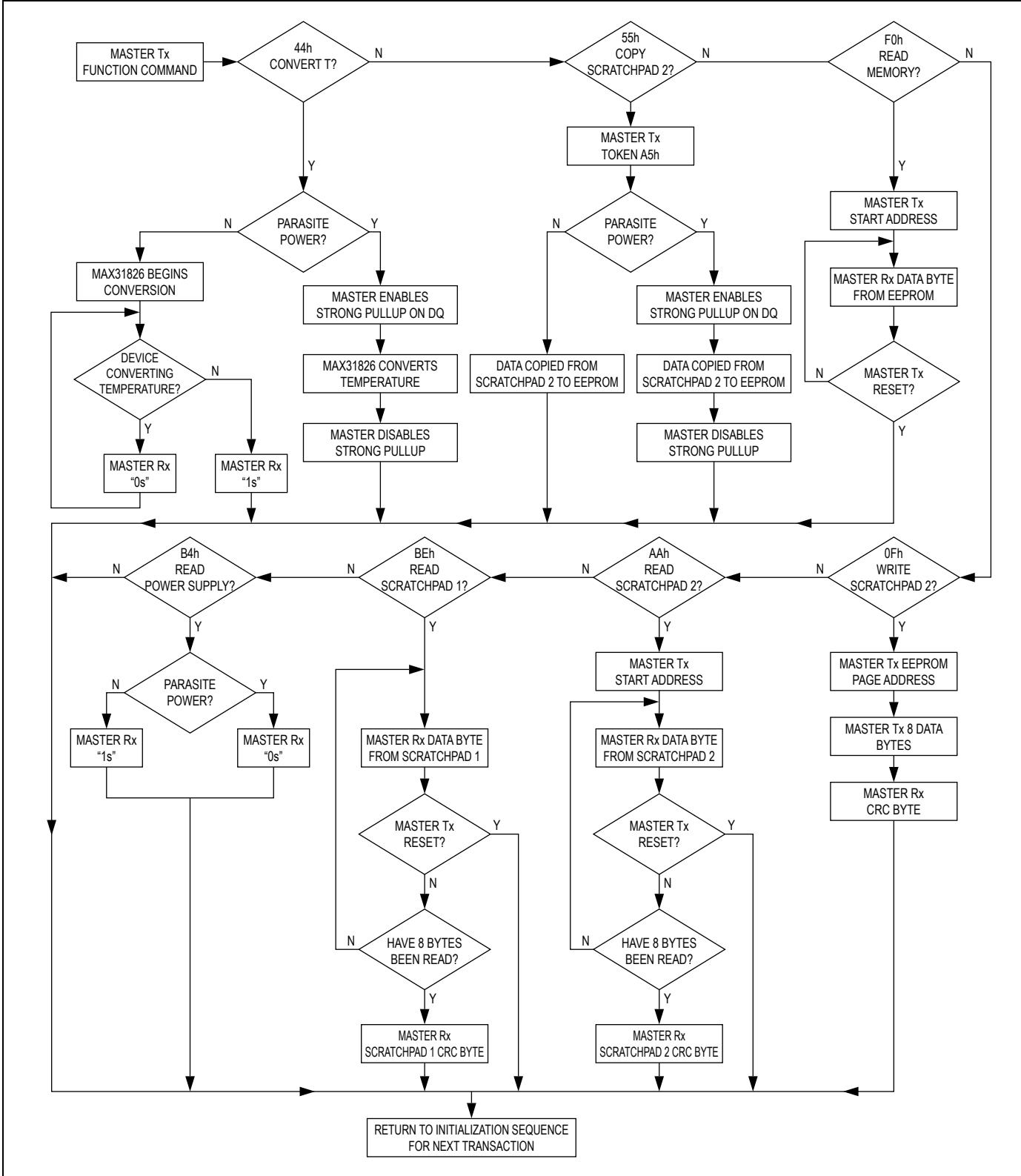
Figure 8. MAX31826 Function Commands Flowchart
NOTE: TEMPERATURE SENSORS ARE ADDRESSEDBY ROM ID, NOT BY BINARY ADDRESS.
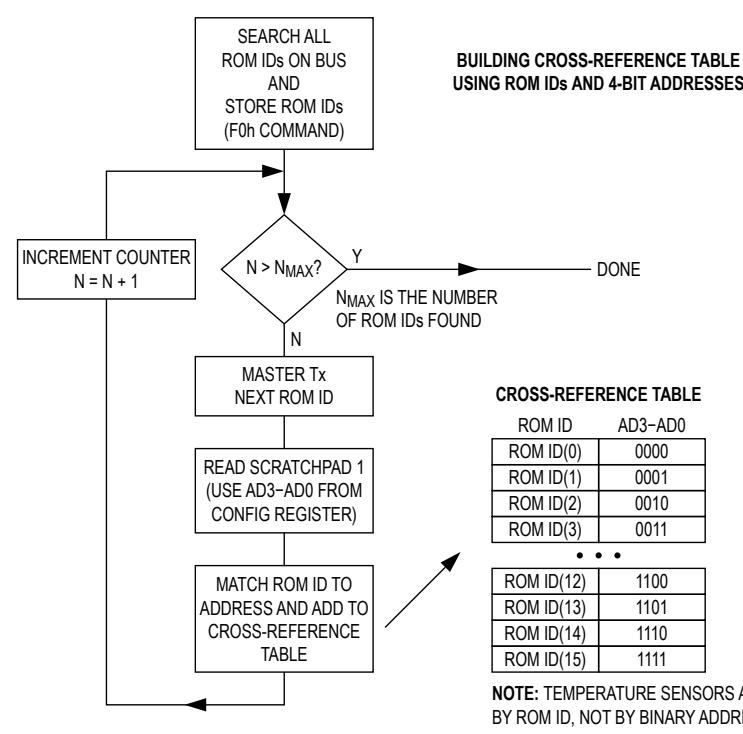
Figure 9. Building a Cross-Reference Table
Locations 40h–7Fh are now locked. Also, location 81h is locked with value 55h. Location 81h cannot be changed to alter the lock status of 40h–7Fh.
Building a Cross-Reference Table
The procedure in Figure 9 uses the Search ROM command to find all MAX31826s on the 1-Wire bus (16 maximum) and then reads each configuration register to match the ROM IDs to the hardwired addresses.
1-Wire Signaling
The device uses a strict 1-Wire communication protocol to ensure data integrity. Several signal types are defined by this protocol: reset pulse, presence pulse, write-zero, write-one, read-zero, and read-one. The bus master initiates all these signals except the presence pulse.
Initialization Procedure: Reset and Presence Pulses
All communication with the device begins with an initialization sequence that consists of a reset pulse from the master followed by a presence pulse from the device. This is illustrated in Figure 10. When the device sends the presence pulse in response to the reset, it is indicating to the master that it is on the bus and ready to operate.
During the initialization sequence, the bus master transmits (Tx) the reset pulse by pulling the 1-Wire bus low for 480µs (min). The bus master then releases the bus and goes into receive mode (Rx). When the bus is released, the 5kΩ pullup resistor pulls the 1-Wire bus high. When the device detects this rising edge, it waits 15µs to 60µs and then transmits a presence pulse by pulling the 1-Wire bus low for 60µs to 240µs.
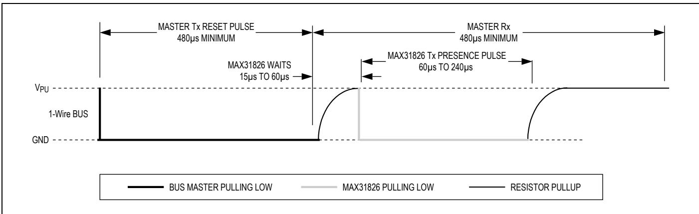
Figure 10. Initialization Timing
Read/Write Time Slots
The bus master writes data to the device during write time slots and reads data from the device during read time slots. One bit of data is transmitted over the 1-Wire bus per time slot.
Write Time Slots
There are two types of write time slots: write-one time slots and write-zero time slots. The bus master uses a write-one time slot to write a logic 1 to the device and a write-zero time slot to write a logic 0 to the device. All write time slots must have a 60µs (min) duration with a 1µs (min) recovery time between individual write slots. Both types of write time slots are initiated by the master pulling the 1-Wire bus low (Figure 11).
To generate a write-one time slot, after pulling the 1-Wire bus low, the bus master must release the 1-Wire bus within 15µs. When the bus is released, the 5kΩ pullup resistor pulls the bus high. To generate a write-zero time slot, after pulling the 1-Wire bus low, the bus master must continue to hold the bus low for the duration of the time slot (at least 60µs).
The device samples the 1-Wire bus during a window that lasts from 15µs to 60µs after the master initiates the write time slot. If the bus is high during the sampling window, a 1 is written to the device. If the line is low, a 0 is written to the device.
Read Time Slots
The device can only transmit data to the master when the master issues read time slots. Therefore, the master must generate read time slots immediately after issuing a Read Scratchpad 1 command or Read Power Supply command, so that the device can provide the requested data. In addition, the master can generate read time slots after issuing a Convert T command to verify the operation status as explained in the MAX31826 Function Commands section.
All read time slots must be 60µs (min) in duration with a 1µs (min) recovery time between slots. A read time slot is initiated by the master device pulling the 1-Wire bus low for a minimum of 1µs (tINIT) and then releasing the bus (Figure 11). After the master initiates the read time slot, the device begins transmitting a 1 or 0 on bus. The device transmits a 1 by leaving the bus high and transmits a 0 by pulling the bus low. When transmitting a 0, the device releases the bus by the end of the time slot, and the pullup resistor pulls the bus back to its high idle state. Output data from the device is valid for 15µs after the falling edge that initiated the read time slot. Therefore, the master must release the bus and then sample the bus state within 15µs from the start of the slot.
Figure 12 illustrates that the sum of tINIT, tRC, and the master sample window must be less than 15µs for a read time slot. tRC is the rise time due to the resistive and capacitive characteristics of the bus. Figure 13 shows that system timing margin is maximized by keeping tINIT and tRC as short as possible and by locating the master sample time during read time slots towards the end of the 15µs period.
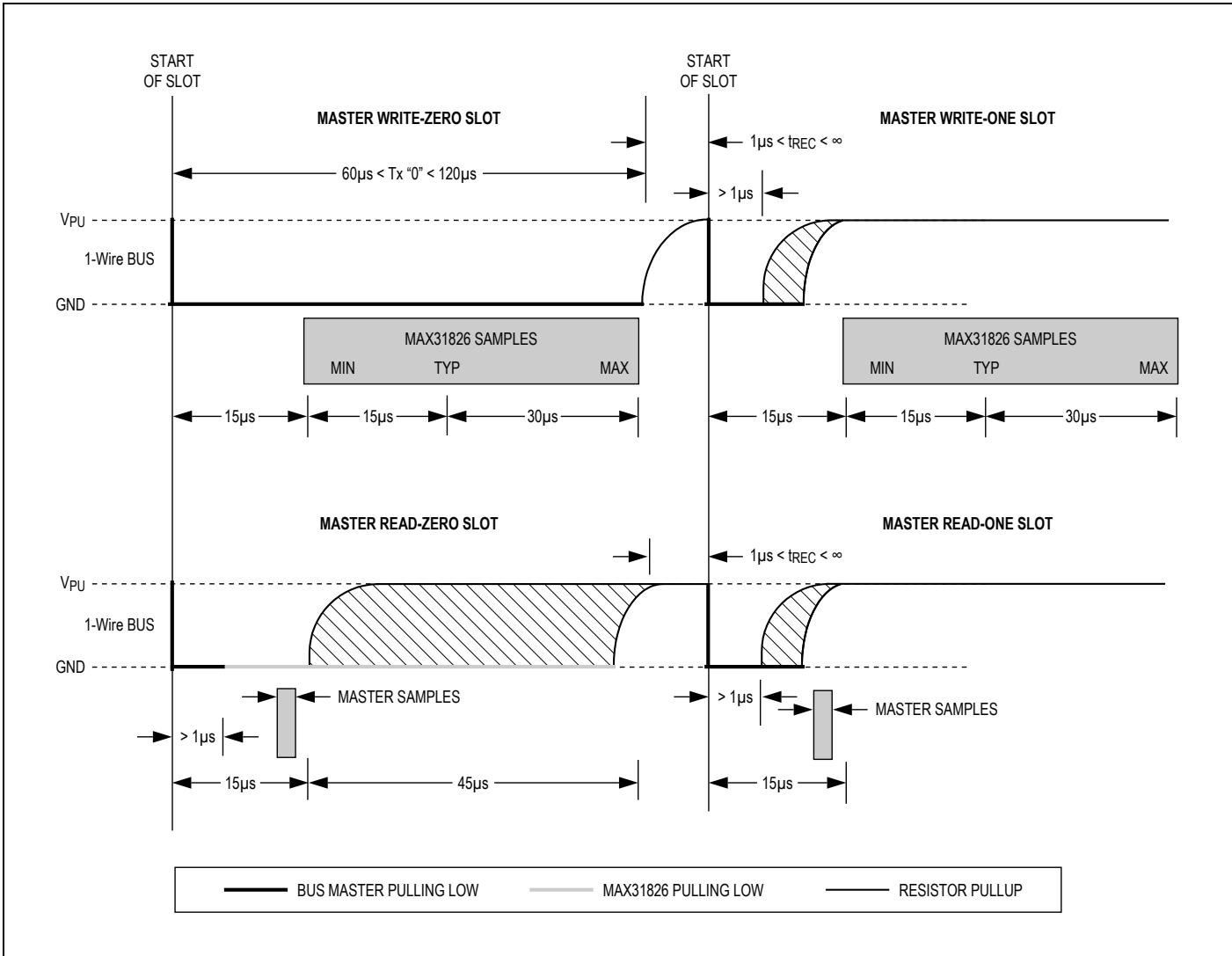
Figure 11. Read/Write Time Slot Timing Diagram
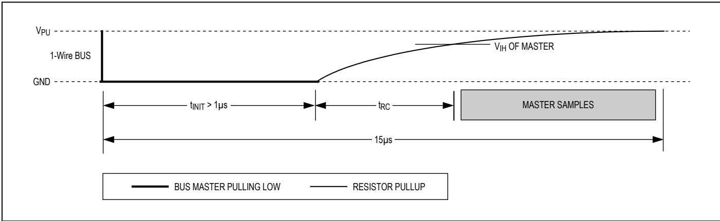
Figure 12. Detailed Master Read-One Timing
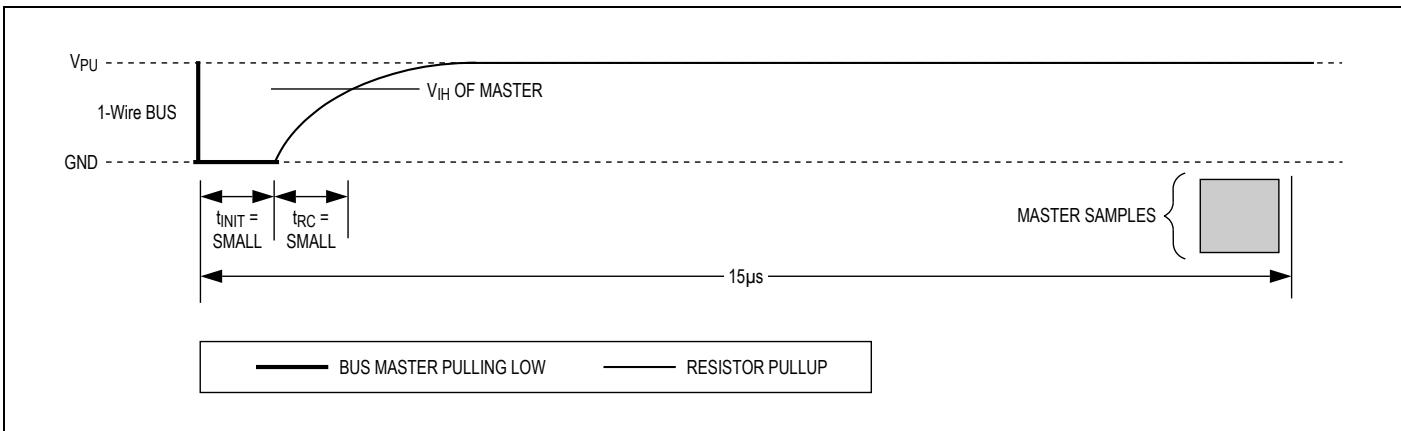
Figure 13. Recommended Master Read-One Timing
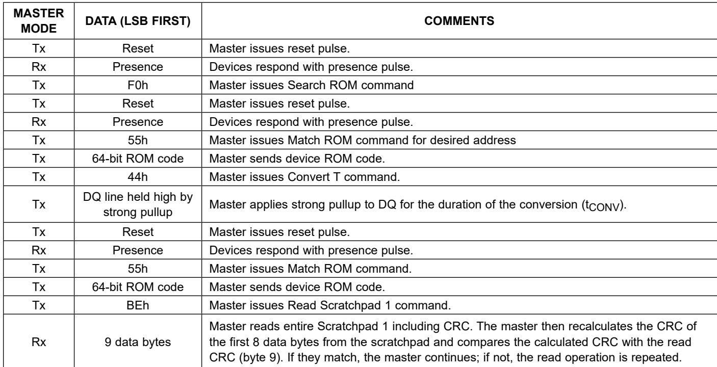
Table 3. Operation Example
| MASTER MODE | DATA (LSB FIRST) | COMMENTS |
| Tx | Reset | Master issues reset pulse. |
| Rx | Presence | Devices respond with presence pulse. |
| Tx | F0h | Master issues Search ROM command |
| Tx | Reset | Master issues reset pulse. |
| Rx | Presence | Devices respond with presence pulse. |
| Tx | 55h | Master issues Match ROM command for desired address |
| Tx | 64-bit ROM code | Master sends device ROM code. |
| Tx | 44h | Master issues Convert T command. |
| Tx | DQ line held high by strong pullup | Master applies strong pullup to DQ for the duration of the conversion ( $t_{CONV}$ ). |
| Tx | Reset | Master issues reset pulse. |
| Rx | Presence | Devices respond with presence pulse. |
| Tx | 55h | Master issues Match ROM command. |
| Tx | 64-bit ROM code | Master sends device ROM code. |
| Tx | BEh | Master issues Read Scratchpad 1 command. |
| Rx | 9 data bytes | Master reads entire Scratchpad 1 including CRC. The master then recalculates the CRC of the first 8 data bytes from the scratchpad and compares the calculated CRC with the read CRC (byte 9). If they match, the master continues; if not, the read operation is repeated. |
Operation Example
Table 3 shows an operation example in which there are multiple devices on the bus using parasite power. The bus master initiates a temperature conversion in a specific MAX31826 and then reads Scratchpad 1 and recalculates the CRC to verify the data.
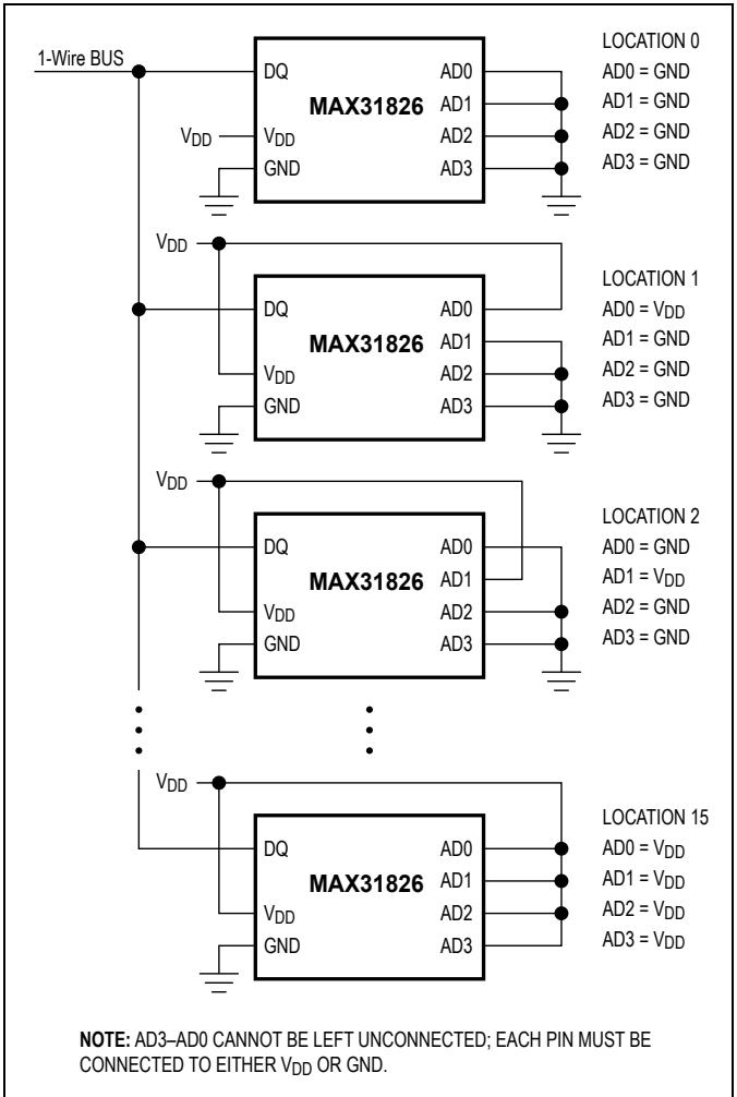
Figure 14. Address Programming Diagram— $\cdot V _ { D D }$ Powered
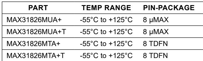
Ordering Information
| PART | TEMP RANGE | PIN-PACKAGE |
| MAX31826MUA+ | -55°C to +125°C | 8 μMAX |
| MAX31826MUA+T | -55°C to +125°C | 8 μMAX |
| MAX31826MTA+ | -55°C to +125°C | 8 TDFN |
| MAX31826MTA+T | -55°C to +125°C | 8 TDFN |
+Denotes a lead(Pb)-free/RoHS-compliant package. T = Tape and reel.
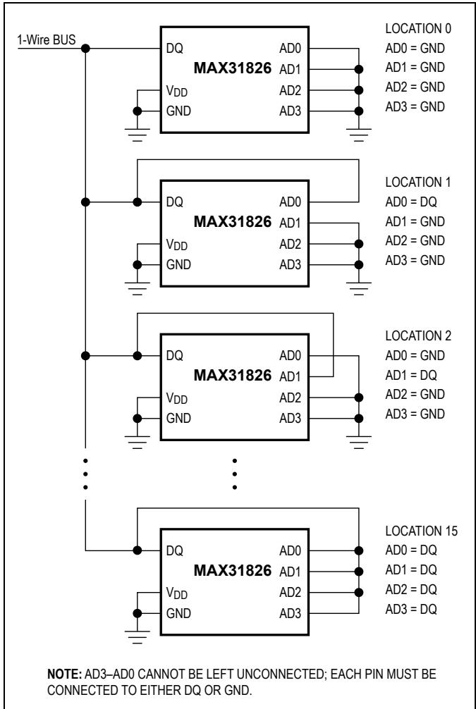
Figure 15. Address Programming Diagram—Parasite Powered
Package Information
For the latest package outline information and land patterns (footprints), go to www.maximintegrated.com/packages. Note that a “+”, “#”, or “-” in the package code indicates RoHS status only. Package drawings may show a different suffix character, but the drawing pertains to the package regardless of RoHS status.
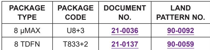
| PACKAGE TYPE | PACKAGE CODE | DOCUMENT NO. | LAND PATTERN NO. |
| 8 μMAX | U8+3 | 21-0036 | 90-0092 |
| 8 TDFN | T833+2 | 21-0137 | 90-0059 |
1-Wire Digital Temperature Sensor with 1Kb Lockable EEPROM
Revision History
| REVISION NUMBER | REVISION DATE | DESCRIPTION | PAGES CHANGED |
| 0 | 3/12 | Initial release | — |
| 1 | 1/21 | Updated EV Kit with new package variant, Updated Benefits and Features, Pin Configuration, Ordering Information, and Package Information. | 1, 5, 21 |
Figures and diagrams from the PDF
Preview the extracted datasheet assets and open any image in a separate tab for closer inspection.






Use this datasheet from any agent
Send the page, markdown, chunks, or search endpoint to ChatGPT, Claude, embedr-app, or your own tooling.