
DAC5311
8-Bit, Single-Channel, Voltage Output, Serial Interface Digital-to-Analog Converter
DACx311 2-V to 5.5-V, 80-µA, 8-Bit, 10-Bit, and 12-Bit, Low-Power, Single-Channel, Digital-to-Analog Converters in SC70 Package
1 Features
• Relative accuracy:
– 0.25 LSB INL (DAC5311: 8-bit)
– 0.5 LSB INL (DAC6311: 10-bit)
– 1 LSB INL (DAC7311: 12-bit)
• microPower operation: 80 μA at 2.0 V
• Power-down: 0.5 μA at 5 V, 0.1 μA at 2.0 V
• Wide power supply: 2.0 V to 5.5 V
• Power-on reset to zero scale
• Straight binary data format
• Low power serial interface with Schmitt-triggered inputs: up to 50 MHz
• On-chip output buffer amplifier, rail-to-rail operation
• SYNC interrupt facility
• Extended temperature range $\scriptscriptstyle - 4 0 ^ { \circ } \mathsf { C }$ to $+ 1 2 5 ^ { \circ } \mathrm { C }$
• Pin-compatible family in a tiny, 6-pin SC70 package
2 Applications
• Portable, battery-powered instruments
• 4-mA to 20-mA loop-powered applications
• Process control and industrial automation
• Programmable voltage and current sources
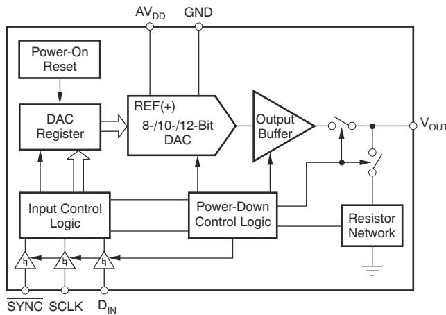
Simplified Schematic
3 Description
The 8-bit DAC5311, 10-bit DAC6311, and 12-bit DAC7311 (DACx311) are low-power, single-channel, voltage output digital-to-analog converters (DACs). The low power consumption in normal operation (0.55 mW at 5 V, reducing to 2.5 μW in power-down mode) makes the DACx311 an excellent choice for portable, battery-operated applications.
These devices are monotonic by design, provide excellent linearity, and minimize undesired codeto-code transient voltages while offering an easy upgrade path within a pin-compatible family. All devices use a versatile, three-wire serial interface that operates at clock rates of up to 50 MHz, and is compatible with standard SPI, QSPI, Microwire, and digital signal processor (DSP) interfaces.
All devices use an external power supply as a reference voltage to set the output range. The devices incorporate a power-on reset (POR) circuit that powers up the DAC output at 0 V and remains at 0 V until a valid write to the device occurs. The DACx311 contain a power-down feature, accessed over the serial interface, that reduces current consumption of the device to 0.1 μA at 2.0 V in power-down mode.
These devices are pin-compatible with the DAC8311 and DAC8411, offering an easy upgrade path from 8‑bit, 10‑bit, and 12‑bit resolution to 14‑bit and 16‑bit. All devices are available in a small, 6‑pin, SC70 (SOT) package. This package offers a flexible, pin- and function-compatible, drop-in DAC within the family over an extended temperature range of –40°C to +125°C.
Device Information(1)
| PART NUMBER(2) | RESOLUTION | PACKAGE SIZE(3) |
| DAC7311 | 12-bit | DCK (SC70, 6)2 mm × 1.5 mm |
| DAC6311 | 10-bit | |
| DAC5311 | 8-bit |
(1) For all available packages, see the package option addendum at the end of the data sheet.
(2) See the Device Comparison Tables.
(3) The package size (length × width) is a nominal value and includes pins, where applicable.
Table of Contents
1 Features....1 8.1 Overview....22
2 Applications....1 8.2 Functional Block Diagram....22
3 Description....1 8.3 Feature Description....22
4 Revision History....2 8.4 Device Functional Modes....24
5 Device Comparison....3 8.5 Programming....25
6 Pin Configuration and Functions....3 9 Application and Implementation....26
7 Specifications....4 9.1 Application Information....26
7.1 Absolute Maximum Ratings....4 9.2 Typical Applications....27
7.2 ESD Ratings....4 9.3 Power Supply Recommendations....30
7.3 Recommended Operating Conditions....4 9.4 Layout....31
7.4 Thermal Information....4 10 Device and Documentation Support....32
7.5 Electrical Characteristics....5 10.1 Receiving Notification of Documentation Updates....32
7.6 Timing Requirements....7 10.2 Support Resources....32
7.7 Timing Diagrams....7 10.3 Trademarks....32
7.8 Typical Characteristics: AV ${DD}$ = 5 V....8 10.4 Electrostatic Discharge Caution....32
7.9 Typical Characteristics: AV ${DD}$ = 3.6 V....15 10.5 Glossary....32
7.10 Typical Characteristics: AV $_{DD}$ = 2.7 V....16
8 Detailed Description....22 11 Mechanical, Packaging, and Orderable Information....32
4 Revision History
NOTE: Page numbers for previous revisions may differ from page numbers in the current version.
Changes from Revision C (July 2015) to Revision D (August 2023) Page
- Updated the numbering format for tables, figures, and cross-references throughout the document.... 1
- Changed Device Information table to show package size instead of body size and added content to show difference among devices.... 1
- Changed power dissipation max value for normal mode at AV $_{DD}$ = 3.6 V to 5.5 V from 0.88 mW to 0.99 mW in Electrical Characteristics .... 5
- Changed I ${DD}$ max value for normal mode at AV ${DD}$ = 3.6 V to 5.5 V from 160 μA to 180 μA in Electrical Characteristics .... 5
Changes from Revision B (May 2013) to Revision C (July 2015) Page - Added ESD Ratings table, and Feature Description, Device Functional Modes, Application and Implementation, Power Supply Recommendations, Layout, Device and Documentation Support, and Mechanical, Packaging, and Orderable Information sections.... 1
- Added Device Comparison section and moved existing tables to this new section.... 3
- Moved Operating Temperature parameter from Electrical Characteristics table to Recommended Operating Conditions table .... 4
- Deleted Parameter Definitions section; definitions moved to new Glossary section.... 32
Changes from Revision A (August 2011) to Revision B (May 2013) Page - Changed all 1.8 V to 2.0 V throughout data sheet.... 1
- Deleted the 1.8-V Typical Characteristics section.... 8
-Changed X-axis for Figure 7-36, Power-Supply Current vs Power-Supply Voltage.... 8
-Changed X-axis for Figure 7-37, Power-Down Current vs Power-Supply Voltage.... 8
Changes from Revision * (August, 2008) to Revision A (August, 2011) Page - Changed specifications and test conditions for input low voltage parameter.... 5
- Changed specifications and test conditions for input high voltage parameter.... 5
5 Device Comparison
Table 5-1. Related Devices
| RELATED DEVICES | 16-BIT | 14-BIT | 12-BIT | 10-BIT | 8-BIT |
| Pin and Function Compatible | DAC8411 | DAC8311 | DAC7311 | DAC6311 | DAC5311 |
Table 5-2. Relative Accuracy and
Differential Nonlinearity
| DEVICE | MAXIMUM RELATIVE ACCURACY (LSB) | MAXIMUM DIFFERENTIAL NONLINEARITY (LSB) |
| DAC5311 | ±0.25 | ±0.25 |
| DAC6311 | ±0.5 | ±0.5 |
| DAC7311 | ±1 | ±1 |
6 Pin Configuration and Functions

Figure 6-1. DCK Package, 6-Pin SC70 (Top View)
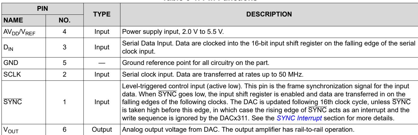
Table 6-1. Pin Functions
| PIN | TYPE | DESCRIPTION | |
| NAME | NO. | ||
| $AV_{DD}/V_{REF}$ | 4 | Input | Power supply input, 2.0 V to 5.5 V. |
| $D_{IN}$ | 3 | Input | Serial Data Input. Data are clocked into the 16-bit input shift register on the falling edge of the serial clock input. |
| GND | 5 | — | Ground reference point for all circuitry on the part. |
| SCLK | 2 | Input | Serial clock input. Data are transferred at rates up to 50 MHz. |
| $\overline{SYNC}$ | 1 | Input | Level-triggered control input (active low). This pin is the frame synchronization signal for the input data. When $\overline{SYNC}$ goes low, the input shift register is enabled and data are transferred in on the falling edges of the following clocks. The DAC is updated following 16th clock cycle, unless $\overline{SYNC}$ is taken high before this edge, in which case the rising edge of $\overline{SYNC}$ acts as an interrupt and the write sequence is ignored by the DACx311. See the SYNC Interrupt section for more details. |
| $V_{OUT}$ | 6 | Output | Analog output voltage from DAC. The output amplifier has rail-to-rail operation. |
7 Specifications
7.1 Absolute Maximum Ratings
over operating free-air temperature range (unless otherwise noted) (1)
| MIN | MAX | UNIT | |||
| Voltage | $AV_{DD}$ to GND | -0.3 | +6 | V | |
| Digital input voltage to GND | -0.3 | $+AV_{DD} + 0.3$ | V | ||
| $V_{OUT}$ to GND | -0.3 | $+AV_{DD} + 0.3$ | V | ||
| $T_J$ | Junction temperature | 150 | °C | ||
| $T_{stg}$ | Storage temperature | -65 | 150 | °C | |
(1) Stresses beyond those listed under Absolute Maximum Ratings may cause permanent damage to the device. These are stress ratings only, which do not imply functional operation of the device at these or any other conditions beyond those indicated under Recommended Operating Conditions. Exposure to absolute-maximum-rated conditions for extended periods may affect device reliability.
7.2 ESD Ratings
| VALUE | UNIT | |||
| $V_{(ESD)}$ | Electrostatic discharge | Human-body model (HBM), per ANSI/ESDA/JEDEC JS-001 $^{(1)}$ | ±1000 | V |
| Charged-device model (CDM), per JEDEC specification JESD22-C101 $^{(2)}$ | ±500 | |||
(1) JEDEC document JEP155 states that 500-V HBM allows safe manufacturing with a standard ESD control process.
(2) JEDEC document JEP157 states that 250-V CDM allows safe manufacturing with a standard ESD control process.
7.3 Recommended Operating Conditions
over operating free-air temperature range (unless otherwise noted)
| MIN | NOM | MAX | UNIT | ||
| $T_A$ | Operating temperature | -40 | 125 | °C | |
| $AV_{DD}$ | Supply voltage | 2 | 5.5 | V | |
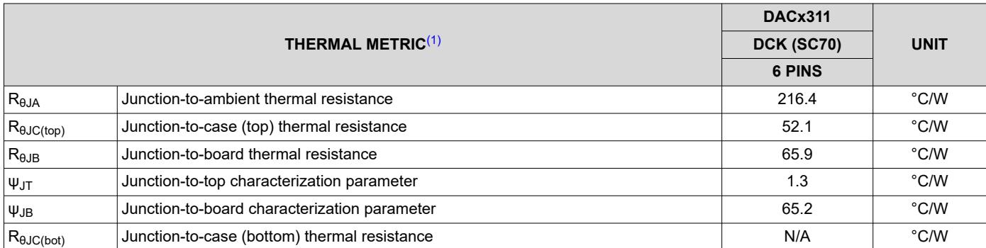
7.4 Thermal Information
| THERMAL METRIC(1) | DACx311 | UNIT | |
| DCK (SC70) | |||
| 6 PINS | |||
| $R_{\theta JA}$ | Junction-to-ambient thermal resistance | 216.4 | °C/W |
| $R_{\theta JC(top)}$ | Junction-to-case (top) thermal resistance | 52.1 | °C/W |
| $R_{\theta JB}$ | Junction-to-board thermal resistance | 65.9 | °C/W |
| $\Psi_{JT}$ | Junction-to-top characterization parameter | 1.3 | °C/W |
| $\Psi_{JB}$ | Junction-to-board characterization parameter | 65.2 | °C/W |
| $R_{\theta JC(bot)}$ | Junction-to-case (bottom) thermal resistance | N/A | °C/W |
(1) For more information about traditional and new thermal metrics, see the application report, Semiconductor and IC Package Thermal Metrics application note.
7.5 Electrical Characteristics
$$
\mathrm{AV} _ {\mathrm{DD}} = 2. 0 \mathrm{V}
$$
$$
R _ {L} = 2 k \Omega
$$
$$
C _ {L} = 2 0 0
$$
$$
T _ {A} = - 4 0 ^ {\circ} C
$$
$$
- 1 2 5 ^ {\circ} \mathrm{C}
$$
| PARAMETER | TEST CONDITIONS | MIN | TYP | MAX | UNIT | |
| $STATIC PERFORMANCE^{(1)}$ | ||||||
| DAC5311 | Resolution | 8 | Bits | |||
| DAC6311 | 10 | Bits | ||||
| DAC7311 | 12 | Bits | ||||
| DAC5311 | Relative accuracy | Measured by the line passing through codes 3 and 252 | ±0.01 | ±0.25 | LSB | |
| DAC6311 | Measured by the line passing through codes 12 and 1012 | ±0.06 | ±0.5 | LSB | ||
| DAC7311 | Measured by the line passing through codes 30 and 4050 | ±0.3 | ±1 | LSB | ||
| DAC5311 | Differential nonlinearity | ±0.01 | ±0.25 | LSB | ||
| DAC6311 | ±0.03 | ±0.5 | LSB | |||
| DAC7311 | ±0.2 | ±1 | LSB | |||
| Offset error | Measured by the line passing through two codes(2) | ±0.05 | ±4 | mV | ||
| Offset error drift | 3 | μV/°C | ||||
| Zero code error | All zeros loaded to the DAC register | 0.2 | mV | |||
| Full-scale error | All ones loaded to DAC register | 0.04 | 0.2 | % of FSR | ||
| Gain error | 0.05 | ±0.15 | % of FSR | |||
| Gain temperature coefficient | $AV_{DD}=5 V$ | ±0.5 | ppm of FSR/°C | |||
| $AV_{DD}=2.0 V$ | ±1.5 | |||||
| OUTPUT CHARACTERISTICS | ||||||
| Output voltage range | 0 | $AV_{DD}$ | V | |||
| $Output voltage settling time^{(3)}$ | $R_L=2 kΩ, C_L=200 pF, AV_{DD}=5 V,$ $1/4 scale to 3/4 scale$ | 6 | 10 | μs | ||
| $R_L=2 MΩ, C_L=470 pF$ | 12 | μs | ||||
| Slew rate | 0.7 | V/μs | ||||
| Capacitive load stability | $R_L=\infty$ | 470 | pF | |||
| $R_L=2 kΩ$ | 1000 | pF | ||||
| Code change glitch impulse | 1 LSB change around major carry | 0.5 | nV-s | |||
| Digital feedthrough | 0.5 | nV-s | ||||
| Power-on glitch impulse | $R_L=2 kΩ, C_L=200 pF, AV_{DD}=5 V$ | 17 | mV | |||
| DC output impedance | 0.5 | Ω | ||||
| Short circuit current | $AV_{DD}=5 V$ | 50 | mA | |||
| $AV_{DD}=3 V$ | 20 | mA | ||||
| Power-up time | Coming out of power-down mode | 50 | μs | |||
| AC PERFORMANCE | ||||||
| SNR | $T_A=25°C, BW=20 kHz, 12-bit level,$ $AV_{DD}=5 V, f_{OUT}=1 kHz, 1st 19 harmonics removed for SNR calculation$ | 81 | dB | |||
| THD | -65 | dB | ||||
| SFDR | 65 | dB | ||||
| SINAD | 65 | dB | ||||
7.5 Electrical Characteristics (continued)
at $\mathsf { A V } _ { \mathsf { D D } } = 2 . 0$ V to 5.5 V, $\mathsf { R } _ { \mathsf { L } } = 2 \mathsf { k } \Omega$ to GND, $\mathsf C _ { \mathrm { L } } = 2 0 0$ pF to GND, and $\mathsf { T } _ { \mathsf { A } } = - 4 0 ^ { \circ } \mathsf { C } \mathsf { t o } + 1 2 5 ^ { \circ } \mathsf { C }$ (unless otherwise noted)
| PARAMETER | TEST CONDITIONS | MIN | TYP | MAX | UNIT | ||
| DAC output noise density(4) | $T_A=25°C, at zero-scale input,$ $f_{OUT}=1 kHz, AV_{DD}=5 V$ | 17 | nV/ $\sqrt{Hz}$ | ||||
| $T_A=25°C, at mid-code input,$ $f_{OUT}=1 kHz, AV_{DD}=5 V$ | 110 | nV/ $\sqrt{Hz}$ | |||||
| DAC output noise(5) | $T_A=+25°C, at mid-code input,$ $0.1 Hz to 10 Hz, AV_{DD}=5 V$ | 3 | μV $_{PP}$ | ||||
| LOGIC INPUTS(3) | |||||||
| Input current | ±1 | μA | |||||
| $V_{IN}L, Input low voltage$ | $AV_{DD}=2.7 V to 5.5 V$ | $0.3 \times AV_{DD}$ | V | ||||
| $AV_{DD}=2.0 V to 2.7 V$ | $0.1 \times AV_{DD}$ | V | |||||
| $V_{IN}H, Input high voltage$ | $AV_{DD}=2.7 V to 5.5 V$ | $0.7 \times AV_{DD}$ | V | ||||
| $AV_{DD}=2.0 V to 2.7 V$ | $0.9 \times AV_{DD}$ | V | |||||
| Pin capacitance | 1.5 | 3 | pF | ||||
| POWER REQUIREMENTS | |||||||
| $AV_{DD}$ | 2.0 | 5.5 | V | ||||
| $I_{DD}$ | Normal mode | $V_{IN}H=AV_{DD}\ and$ $V_{IN}L=GND, at$ $midscale code^{(6)}$ | $AV_{DD}=3.6 V to 5.5 V$ | 110 | 180 | μA | |
| $AV_{DD}=2.7 V to 3.6 V$ | 95 | 150 | μA | ||||
| $AV_{DD}=2.0 V to 2.7 V$ | 80 | 140 | μA | ||||
| All power-down mode | $V_{IN}H=AV_{DD}\ and$ $V_{IN}L=GND, at$ $midscale code^{(6)}$ | $AV_{DD}=3.6 V to 5.5 V$ | 0.5 | 3.5 | μA | ||
| $AV_{DD}=2.7 V to 3.6 V$ | 0.4 | 3 | μA | ||||
| $AV_{DD}=2.0 V to 2.7 V$ | 0.1 | 2 | μA | ||||
| Power dissipation | Normal mode | $V_{IN}H=AV_{DD}\ and$ $V_{IN}L=GND, at$ $midscale code^{(6)}$ | $AV_{DD}=3.6 V to 5.5 V$ | 0.55 | 0.99 | mW | |
| $AV_{DD}=2.7 V to 3.6 V$ | 0.25 | 0.54 | mW | ||||
| $AV_{DD}=2.0 V to 2.7 V$ | 0.14 | 0.38 | mW | ||||
| All power-down mode | $V_{IN}H=AV_{DD}\ and$ $V_{IN}L=GND, at$ $midscale code^{(6)}$ | $AV_{DD}=3.6 V to 5.5 V$ | 2.50 | 19.2 | μW | ||
| $AV_{DD}=2.7 V to 3.6 V$ | 1.08 | 10.8 | μW | ||||
| $AV_{DD}=2.0 V to 2.7 V$ | 0.72 | 8.1 | μW | ||||
(1) Linearity calculated using a reduced code range of 3 to 252 for 8-bit, 12 to 1012 for 10bit, and 30 to 4050 for 12-bit, output unloaded.
(2) Straight line passing through codes 3 and 252 for 8-bit, 12 and 1012 for 10-bit, and 30 and 4050 for 12-bit, output unloaded.
(3) Specified by design and characterization, not production tested.
(4) For more details, see Figure 7-23.
(5) For more details, see Figure 7-24.
(6) For more details, see Figure 7-16 and Figure 7-58.
7.6 Timing Requirements
at $\ 4 0 ^ { \circ } \mathsf { C }$ to ${ 1 2 5 ^ { \circ } \mathsf { C } } ,$ and $A V _ { \mathsf { D D } } = 2 \mathsf { V }$ to 5.5 V (unless otherwise noted)(1)
| MIN | NOM | MAX | UNIT | |||
| $f_{(SCLK)}$ | Serial clock frequency | $AV_{DD}=2.0 V to 3.6 V$ | 20 | MHz | ||
| $AV_{DD}=3.6 V to 5.5 V$ | 50 | |||||
| $t_1$ | SCLK cycle time | $AV_{DD}=2.0 V to 3.6 V$ | 50 | ns | ||
| $AV_{DD}=3.6 V to 5.5 V$ | 20 | |||||
| $t_2$ | SCLK high time | $AV_{DD}=2.0 V to 3.6 V$ | 25 | ns | ||
| $AV_{DD}=3.6 V to 5.5 V$ | 10 | |||||
| $t_3$ | SCLK low time | $AV_{DD}=2.0 V to 3.6 V$ | 25 | ns | ||
| $AV_{DD}=3.6 V to 5.5 V$ | 10 | |||||
| $t_4$ | SYNC to SCLK rising edge setup time | $AV_{DD}=2.0 V to 3.6 V$ | 0 | ns | ||
| $AV_{DD}=3.6 V to 5.5 V$ | 0 | |||||
| $t_5$ | Data setup time | $AV_{DD}=2.0 V to 3.6 V$ | 5 | ns | ||
| $AV_{DD}=3.6 V to 5.5 V$ | 5 | |||||
| $t_6$ | Data hold time | $AV_{DD}=2.0 V to 3.6 V$ | 4.5 | ns | ||
| $AV_{DD}=3.6 V to 5.5 V$ | 4.5 | |||||
| $t_7$ | SCLK falling edge to SYNC rising edge | $AV_{DD}=2.0 V to 3.6 V$ | 0 | ns | ||
| $AV_{DD}=3.6 V to 5.5 V$ | 0 | |||||
| $t_8$ | Minimum SYNC high time | $AV_{DD}=2.0 V to 3.6 V$ | 50 | ns | ||
| $AV_{DD}=3.6 V to 5.5 V$ | 20 | |||||
| $t_9$ | 16th SCLK falling edge to SYNC falling edge | $AV_{DD}=2.0 V to 3.6 V$ | 100 | ns | ||
| $AV_{DD}=3.6 V to 5.5 V$ | 100 | |||||
| $t_{10}$ | SYNC rising edge to 16th SCLK falling edge (for successful SYNC interrupt) | $AV_{DD}=2.0 V to 3.6 V$ | 15 | ns | ||
| $AV_{DD}=3.6 V to 5.5 V$ | 15 | |||||
(1) All input signals are specified with $\mathfrak { t } _ { \mathtt { R } } = \mathfrak { t } _ { \mathtt { F } } = 3$ ns (10% to 90% of $\mathsf { A V } _ { \mathsf { D D } } )$ and timed from a voltage level of $( \mathsf { V } _ { \mathsf { I L } } + \mathsf { V } _ { \mathsf { I H } } ) / 2$
7.7 Timing Diagrams

Figure 7-1. Serial Write Operation
7.8 Typical Characteristics: $\Delta V _ { \mathsf { D D } } = 5 \mathsf { V }$
at $\mathsf { T } _ { \mathsf { A } } = 2 5 ^ { \circ } \mathsf { C } , \mathsf { A } \mathsf { V } _ { \mathsf { D } \mathsf { D } } = 5 \mathsf { V } ,$ and DAC loaded with midscale code (unless otherwise noted)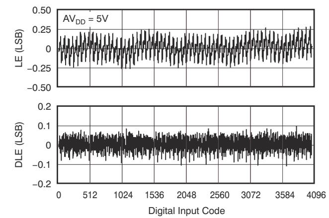
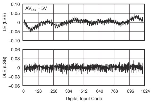
Figure 7-2. DAC7311 12-Bit Linearity Error and Differential Linearity Error vs Code (–40°C)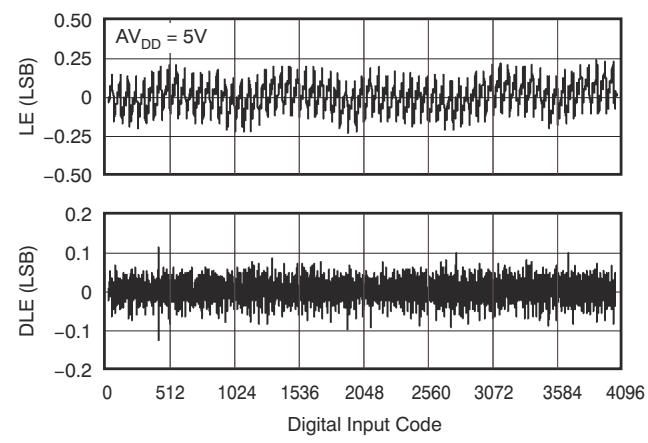
Figure 7-3. DAC6311 10-Bit Linearity Error and Differential Linearity Error vs Code (–40°C)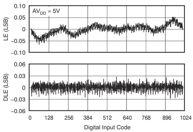
Figure 7-4. DAC7311 12-Bit Linearity Error and Differentia Linearity Error vs Code (25°C)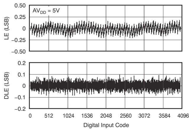
Figure 7-6. DAC7311 12-Bit Linearity Error and Differentia Linearity Error vs Code (125°C)
Figure 7-5. DAC6311 10-Bit Linearity Error and Differential Linearity Error vs Code (25°C)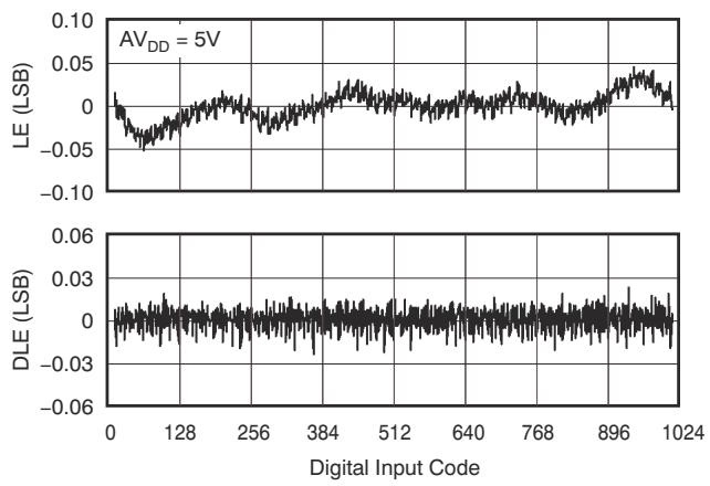
Figure 7-7. DAC6311 10-Bit Linearity Error and Differential Linearity Error vs Code (125°C)
7.8 Typical Characteristics: $\Delta V _ { \mathsf { D D } } = 5 \mathsf { V }$ (continued)
at $\mathsf { T } _ { \mathsf { A } } = 2 5 ^ { \circ } \mathsf { C } , \mathsf { A } \mathsf { V } _ { \mathsf { D } \mathsf { D } } = 5 \mathsf { V } ,$ and DAC loaded with midscale code (unless otherwise noted)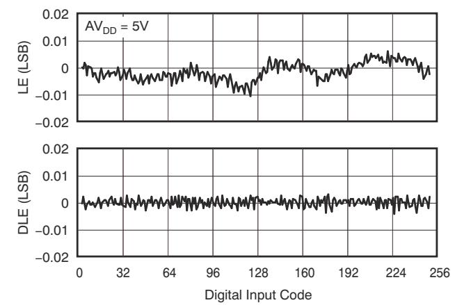
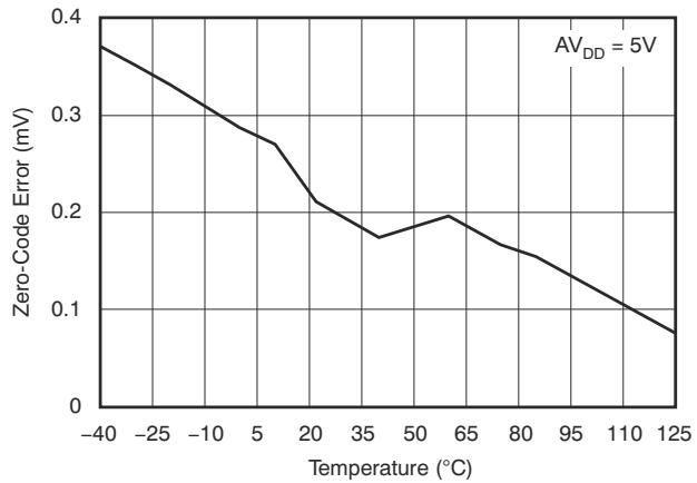
Figure 7-8. DAC5311 8-Bit Linearity Error and Differential Linearity Error vs Code (–40°C)
Figure 7-9. Zero-Code Error vs Temperature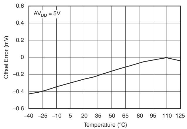
Figure 7-10. DAC5311 8-Bit Linearity Error and Differentia Linearity Error vs Code (25°C)
Figure 7-12. DAC5311 8-Bit Linearity Error and Differentia Linearity Error vs Code (125°C)
Figure 7-11. Offset Error vs Temperature
Figure 7-13. Full-Scale Error vs Temperature
7.8 Typical Characteristics: $\Delta V _ { \mathsf { D D } } = 5 \mathsf { V }$ (continued)
at $\mathsf { T } _ { \mathsf { A } } = 2 5 ^ { \circ } \mathsf { C } , \mathsf { A } \mathsf { V } _ { \mathsf { D } \mathsf { D } } = 5 \mathsf { V } ,$ and DAC loaded with midscale code (unless otherwise noted)
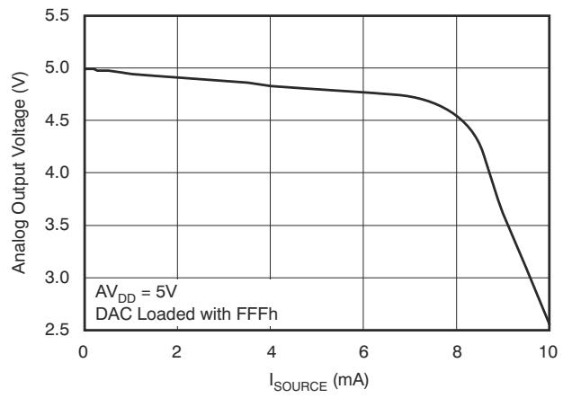

Figure 7-14. Source Current at Positive Rail
Figure 7-15. Sink Current at Negative Rai
Figure 7-16. Power-Supply Current vs Digital Input Code
Figure 7-18. Power-Supply Current vs Temperature
Figure 7-17. Power-Supply Current vs Logic Input Voltage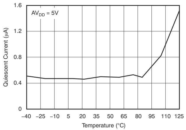
Figure 7-19. Power-Down Current vs Temperature
7.8 Typical Characteristics: $\Delta V _ { \mathsf { D D } } = 5 \mathsf { V }$ (continued)
at $\mathsf { T } _ { \mathsf { A } } = 2 5 ^ { \circ } \mathsf { C } , \mathsf { A } \mathsf { V } _ { \mathsf { D } \mathsf { D } } = 5 \mathsf { V } ,$ and DAC loaded with midscale code (unless otherwise noted)

Figure 7-20. Total Harmonic Distortion vs Output Frequency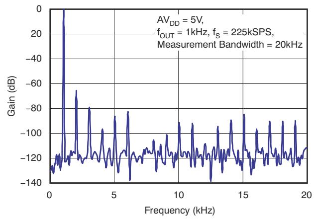
Figure 7-21. Signal-to-Noise Ratio vs Output Frequency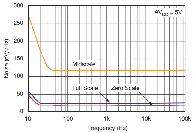
Figure 7-22. Power Spectral Density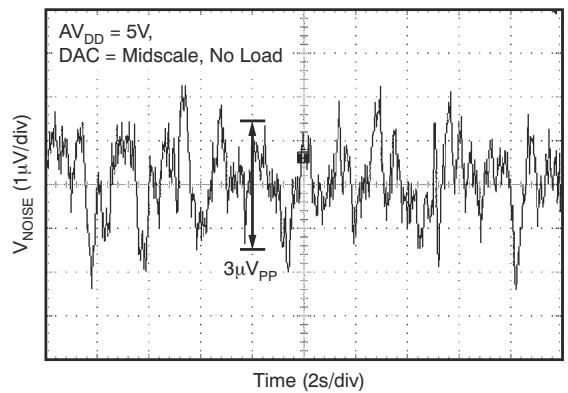
Figure 7-24. DAC Output Noise, 0.1-Hz to 10-Hz Bandwidth
Figure 7-23. DAC Output Noise Density vs Frequency
Figure 7-25. Clock Feedthrough, 5-V, 2-MHz, Midscale
7.8 Typical Characteristics: $\Delta V _ { \mathsf { D D } } = 5 \mathsf { V }$ (continued)
at $\mathsf { T } _ { \mathsf { A } } = 2 5 ^ { \circ } \mathsf { C } , \mathsf { A } \mathsf { V } _ { \mathsf { D } \mathsf { D } } = 5 \mathsf { V } ,$ and DAC loaded with midscale code (unless otherwise noted)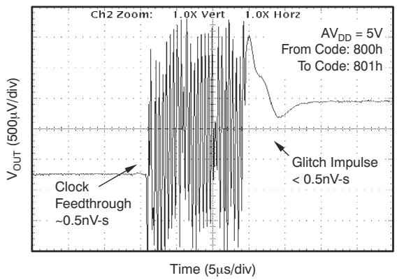
Figure 7-26. Glitch Energy, 5-V, 12-Bit, 1-LSB Step, Rising Edge
Figure 7-28. Glitch Energy, 5-V, 8-Bit, 1-LSB Step, Rising Edge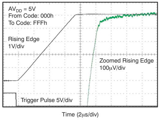
Figure 7-30. Full-Scale Settling Time, 5-V Rising Edge
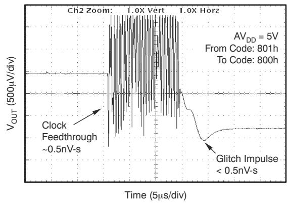
Figure 7-27. Glitch Energy, 5-V, 12-Bit, 1-LSB Step, Falling Edge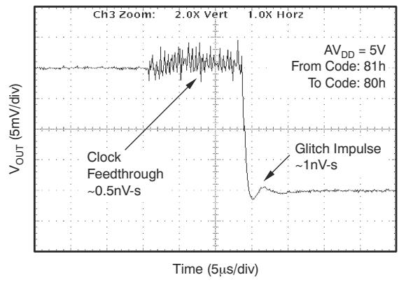
Figure 7-29. Glitch Energy, 5-V, 8-Bit, 1-LSB Step, Falling Edge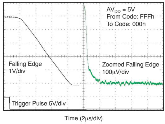
Figure 7-31. Full-Scale Settling Time, 5-V Falling Edge
7.8 Typical Characteristics: $\Delta V _ { \mathsf { D D } } = 5 \mathsf { V }$ (continued)
at $\mathsf { T } _ { \mathsf { A } } = 2 5 ^ { \circ } \mathsf { C } , \mathsf { A } \mathsf { V } _ { \mathsf { D } \mathsf { D } } = 5 \mathsf { V } ,$ and DAC loaded with midscale code (unless otherwise noted)

Figure 7-32. Half-Scale Settling Time, 5-V Rising Edge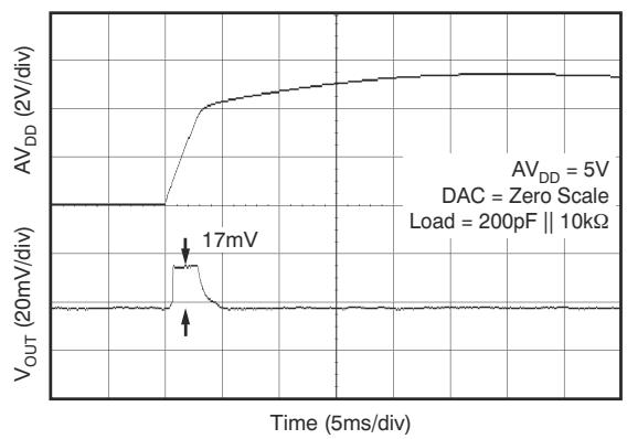

Figure 7-33. Half-Scale Settling Time 5-V Falling Edge
Figure 7-34. Power-On Reset to 0-V Power-On Glitch
Figure 7-36. Power-Supply Current vs Power-Supply Voltage
Figure 7-35. Power-Off Glitch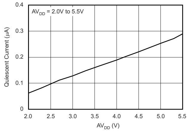
Figure 7-37. Power-Down Current vs Power-Supply Voltage
7.8 Typical Characteristics: $\Delta V _ { \mathsf { D D } } = 5 \mathsf { V }$ (continued)
at $\mathsf { T } _ { \mathsf { A } } = 2 5 ^ { \circ } \mathsf { C } , \mathsf { A } \mathsf { V } _ { \mathsf { D } \mathsf { D } } = 5 \mathsf { V } ,$ and DAC loaded with midscale code (unless otherwise noted)

Figure 7-38. Power-Supply Current Histogram
7.9 Typical Characteristics: $\mathsf { \Delta } \mathsf { A } \mathsf { V } _ { \mathsf { D } \mathsf { D } } = 3 . 6 \mathsf { V }$
at $\mathsf { T } _ { \mathsf { A } } = 2 5 ^ { \circ } \mathsf { C } , \mathsf { A V } _ { \mathsf { D D } } = 3 . 6 \mathsf { V } ,$ and DAC loaded with midscale code (unless otherwise noted)

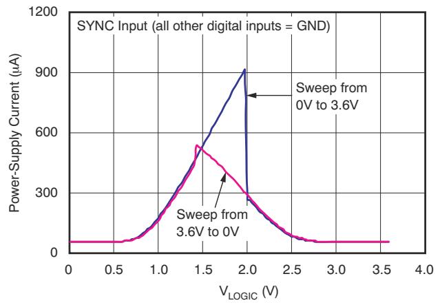
Figure 7-39. Power-Down Current vs Temperature
Figure 7-40. Power-Supply Current vs Logic Input Voltage
Figure 7-41. Power-Supply Current Histogram
Figure 7-42. Source Current at Positive Rail
Figure 7-43. Sink Current at Negative Rail
7.10 Typical Characteristics: $ { \mathsf { A V } } _ { \mathsf { D D } } = 2 . 7 \ : \mathsf { V }$
at $\mathsf { T } _ { \mathsf { A } } = 2 5 ^ { \circ } \mathsf { C } , \mathsf { A V } _ { \mathsf { D D } } = 2 . 7 \mathsf { V } ,$ and DAC loaded with midscale code (unless otherwise noted)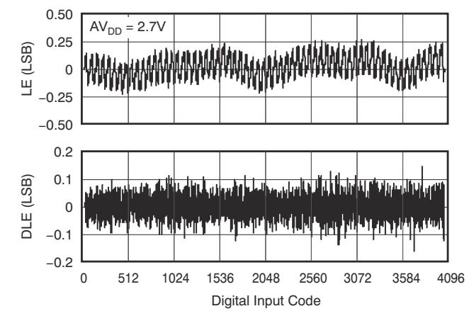

Figure 7-44. DAC7311 12-Bit Linearity Error and Differential Linearity Error vs Code (–40°C)
Figure 7-46. DAC7311 12-Bit Linearity Error and Differential Linearity Error vs Code (25°C)
Figure 7-45. DAC6311 10-Bit Linearity Error and Differential Linearity Error vs Code (–40°C)
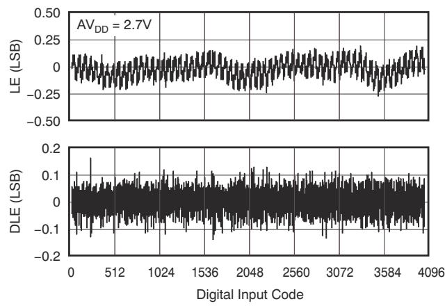
Figure 7-48. DAC7311 12-Bit Linearity Error and Differential Linearity Error vs Code (125°C)
Figure 7-47. DAC6311 10-Bit Linearity Error and Differential Linearity Error vs Code (25°C)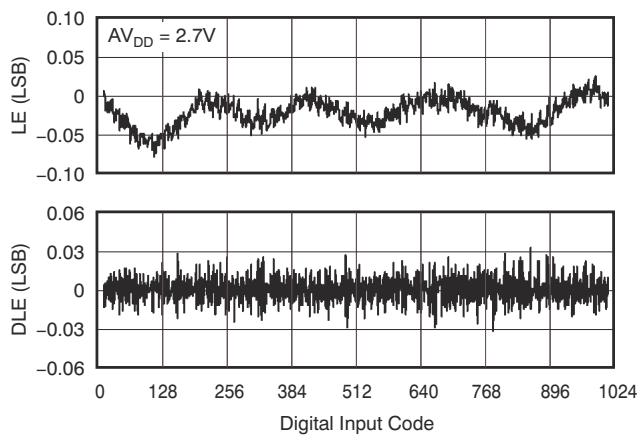
Figure 7-49. DAC6311 10-Bit Linearity Error and Differential Linearity Error vs Code (125°C)
7.10 Typical Characteristics: $\Delta V _ { \mathsf { D D } } = 2 . 7$ V (continued)
at $\mathsf { T } _ { \mathsf { A } } = 2 5 ^ { \circ } \mathsf { C } , \mathsf { A V } _ { \mathsf { D D } } = 2 . 7 \mathsf { V } ,$ and DAC loaded with midscale code (unless otherwise noted)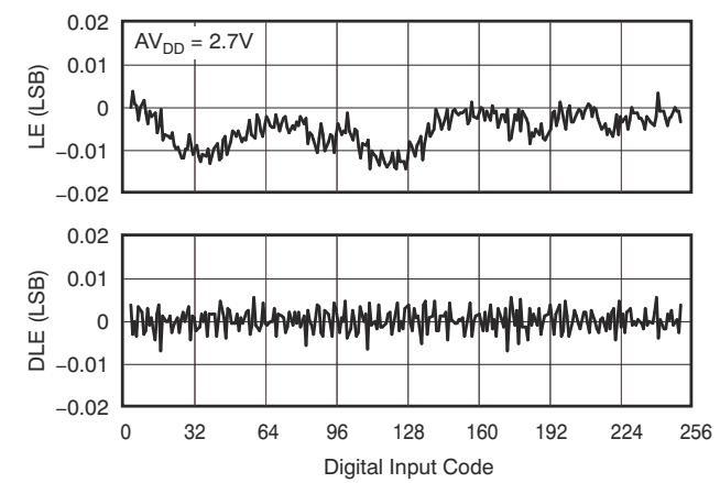
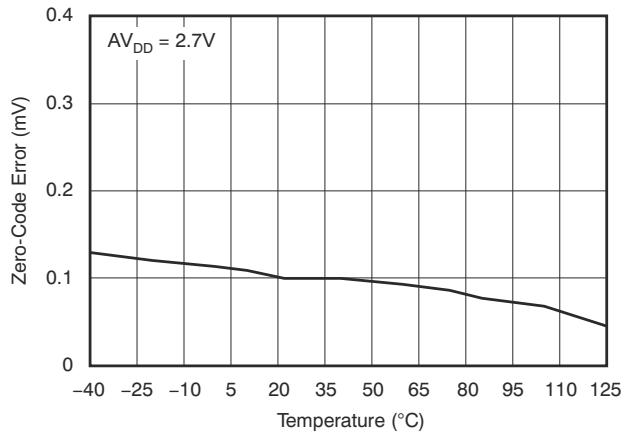
Figure 7-50. DAC5311 8-Bit Linearity Error and Differential Linearity Error vs Code (–40°C)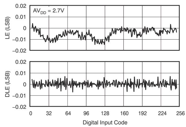
Figure 7-51. Zero-Code Error vs Temperature
Figure 7-52. DAC5311 8-Bit Linearity Error and Differentia Linearity Error vs Code (25°C)
Figure 7-54. DAC5311 8-Bit Linearity Error and Differentia Linearity Error vs Code (125°C)
Figure 7-53. Offset Error vs Temperature
Figure 7-55. Full-Scale Error vs Temperature
7.10 Typical Characteristics: $\Delta V _ { \mathsf { D D } } = 2 . 7$ V (continued)
at $\mathsf { T } _ { \mathsf { A } } = 2 5 ^ { \circ } \mathsf { C } , \mathsf { A V } _ { \mathsf { D D } } = 2 . 7 \mathsf { V } ,$ and DAC loaded with midscale code (unless otherwise noted)

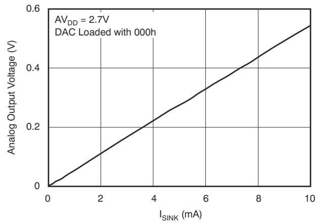
Figure 7-56. Source Current at Positive Rail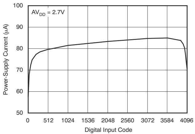
Figure 7-57. Sink Current at Negative Rai
Figure 7-58. Power-Supply Current vs Digital Input Code
Figure 7-60. Power-Supply Current vs Temperature
Figure 7-59. Power-Supply Current vs Logic Input Voltage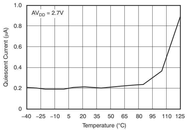
Figure 7-61. Power-Down Current vs Temperature
7.10 Typical Characteristics: $\Delta V _ { \mathsf { D D } } = 2 . 7$ V (continued)
at $\mathsf { T } _ { \mathsf { A } } = 2 5 ^ { \circ } \mathsf { C } , \mathsf { A V } _ { \mathsf { D D } } = 2 . 7 \mathsf { V } ,$ and DAC loaded with midscale code (unless otherwise noted)

Figure 7-62. Total Harmonic Distortion vs Output Frequency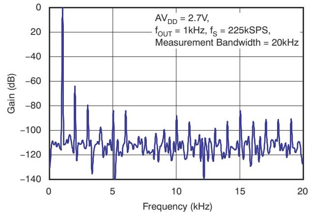
Figure 7-63. Signal-to-Noise Ratio vs Output Frequency
Figure 7-64. Power Spectral Density
Figure 7-66. Clock Feedthrough 2.7-V, 20-MHz, Midscale
Figure 7-65. Power-Supply Current Histogram
Figure 7-67. Glitch Energy, 2.7-V, 12-Bit, 1-LSB Step, Rising Edge
7.10 Typical Characteristics: $\Delta V _ { \mathsf { D D } } = 2 . 7$ V (continued)
at $\mathsf { T } _ { \mathsf { A } } = 2 5 ^ { \circ } \mathsf { C } , \mathsf { A V } _ { \mathsf { D D } } = 2 . 7 \mathsf { V } ,$ and DAC loaded with midscale code (unless otherwise noted)


Figure 7-68. Glitch Energy, 2.7-V, 12-Bit, 1-LSB Step, Falling Edge
Figure 7-69. Glitch Energy, 2.7-V, 8-Bit, 1-LSB Step, Rising Edge
Figure 7-70. Glitch Energy, 2.7-V, 8-Bit, 1-LSB Step, Falling Edge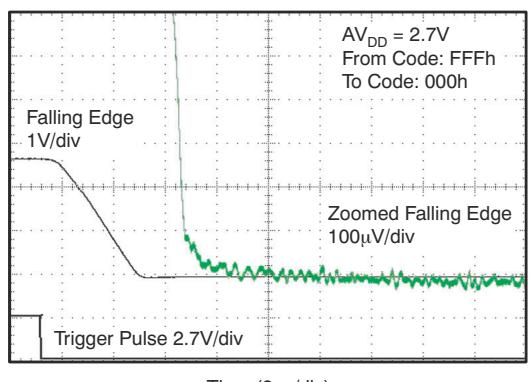
Figure 7-72. Full-Scale Settling Time, 2.7-V Falling Edge
Figure 7-71. Full-Scale Settling Time, 2.7-V Rising Edge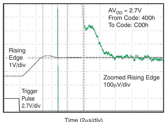
Figure 7-73. Half-Scale Settling Time, 2.7-V Rising Edge
7.10 Typical Characteristics: $\Delta V _ { \mathsf { D D } } = 2 . 7$ V (continued)
at $\mathsf { T } _ { \mathsf { A } } = 2 5 ^ { \circ } \mathsf { C } , \mathsf { A V } _ { \mathsf { D D } } = 2 . 7 \mathsf { V } ,$ and DAC loaded with midscale code (unless otherwise noted)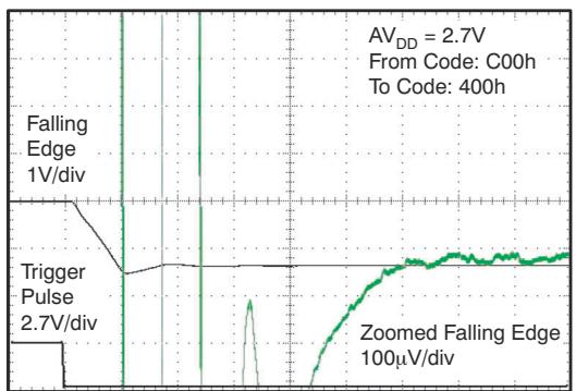
Figure 7-74. Half-Scale Settling Time, 2.7-V Falling Edge

Figure 7-75. Power-On Reset to 0-V Power-On Glitch
Time (10ms/div)
Figure 7-76. Power-Off Glitch
8 Detailed Description
8.1 Overview
The 8-bit DAC5311, 10-bit DAC6311, and 12-bit DAC7311 devices (DACx311) are low-power, single-channel, voltage output DACs. These devices are monotonic by design, provide excellent linearity, and minimize undesired code-to-code transient voltages while offering an easy upgrade path within a pin-compatible family. All devices use a versatile, three-wire serial interface that operates at clock rates of up to 50 MHz and is compatible with standard SPI, QSPI, Microwire, and digital signal processor (DSP) interfaces.
8.2 Functional Block Diagram

8.3 Feature Description
8.3.1 DAC Section
The DACx311 are fabricated using Texas Instruments' proprietary HPA07 process technology. The architecture consists of a string DAC followed by an output buffer amplifier. Because there is no reference input pin, the power supply $( \mathsf { A V } _ { \mathsf { D D } } )$ acts as the reference. Figure 8-1 shows a block diagram of the DAC architecture.

Figure 8-1. DACx311 Architecture
The input coding to the DACx311 is straight binary, so the ideal output voltage is given by:
$$
V _ {O U T} = A V _ {D D} \times \frac {D}{2 ^ {n}}\tag{1}
$$
where
• n = resolution in bits; either 8 (DAC5311), 10 (DAC6311), or 12 (DAC7311).
• D = decimal equivalent of the binary code that is loaded to the DAC register. D ranges from 0 to 255 for 8-bit DAC5311, 0 to 1023 for the 10-bit DAC6311, and 0 to 4095 for the 12-bit DAC7311.
8.3.2 Resistor String
Figure 8-2 shows the resistor string section, which is a string of resistors, each of value R. The code loaded into the DAC register determines at which node on the string the voltage is tapped off to be fed into the output amplifier by closing one of the switches connecting the string to the amplifier. The resistor string architecture is inherently monotonic.
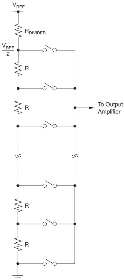
Figure 8-2. Resistor String
8.3.3 Output Amplifier
The output buffer amplifier is capable of generating rail-to-rail voltages on the output, which gives an output range of 0 V to AV . The output amplifier is capable of driving a load of 2 kΩ in parallel with 1000 pF to GND. The source and sink capabilities of the output amplifier can be seen in the Typical Characteristics section for the given voltage input. The slew rate is 0.7 V/μs with a half-scale settling time of typically 6 μs with the output unloaded.
8.3.4 Power-On Reset
The DACx311 contain a power-on reset circuit that controls the output voltage during power up. On power up, the DAC register is filled with zeros and the output voltage is 0 V. The DAC register remains that way until a valid write sequence is made to the DAC. This design is useful in applications where knowing the state of the DAC output while powering up is important.
The occurring power-on glitch impulse is only a few millivolts (typically, 17 mV; see Figure 7-34).
8.4 Device Functional Modes
8.4.1 Power-Down Modes
The DACx311 contain four separate modes of operation. These modes are programmable by setting two bits (PD1 and PD0) in the control register. Table 8-1 shows how the state of the bits corresponds to the mode of operation of the device.
Table 8-1. Modes of Operation for the DACx311
| PD1 | PD0 | OPERATING MODE |
| NORMAL MODE | ||
| 0 | 0 | Normal Operation |
| POWER-DOWN MODES | ||
| 0 | 1 | Output 1 kΩ to GND |
| 1 | 0 | Output 100 kΩ to GND |
| 1 | 1 | High-Z |
When both bits are set to 0, the device works normally with a standard power consumption of typically 80 μA at 2 V. However, for the three power-down modes, the typical supply current falls to 0.5 μA at 5 V, 0.4 μA at 3 V, and 0.1 μA at 2 V. Not only does the supply current fall, but the output stage is also internally switched from the output of the amplifier to a resistor network of known values. The advantage of this architecture is that the output impedance of the part is known while the part is in power-down mode. There are three different options: the output is connected internally to GND either through a 1-kΩ resistor or a 100-kΩ resistor, or is left open-circuited (High-Z). Figure 8-3 illustrates the output stage.
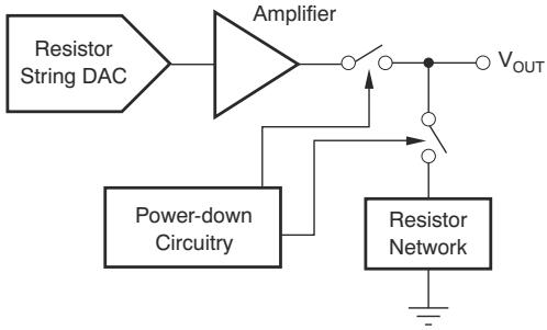
Figure 8-3. Output Stage During Power-Down
All linear circuitry is shut down when the power-down mode is activated. However, the contents of the DAC register are unaffected when in power-down. The time to exit power-down is typically $5 0 ~ \mu \ s$ for $\mathsf { A V } _ { \mathsf { D D } } = 5 \mathrm { V }$ and $\mathsf { A V } _ { \mathsf { D D } } = 3 \mathsf { V } .$
8.5 Programming
8.5.1 Serial Interface
The DACx311 has a 3-wire serial interface (SYNC, SCLK, and DIN) compatible with SPI, QSPI, and Microwire interface standards, as well as most DSPs. For an example of a typical write sequence, see Figure 7-1.
8.5.1.1 Input Shift Register
The input shift register is 16 bits wide, as shown in Table 8-2. The first two bits (PD0 and PD1) are reserved control bits that set the desired mode of operation (normal mode or any one of three power-down modes) as indicated in Table 8-1.
The remaining data bits are either 12 (DAC7311), 10 (DAC6311), or 8 (DAC5311) data bits, followed by don't care bits, as shown in Table 8-2, Table 8-3, and Table 8-4, respectively.
Table 8-2. DAC5311 8-Bit Data Input Register
| DB15 DB14 | DB6 DB5 | DB0 | |||||||||||||
| PD1 | PD0 | D7 | D6 | D5 | D4 | D3 | D2 | D1 | D0 | X | X | X | X | X | X |
LEGEND: R/W = Read/Write; R = Read only; -n = value after reset
Table 8-3. DAC6311 10-Bit Data Input Register
| DB15 DB14 | DB4 DB3 | DB0 | ||||||||||||
| PD1 | PD0 | D9 | D8 | D7 | D6 | D5 | D4 | D3 | D2 | D1 | D0 | X | X | X |
LEGEND: R/W = Read/Write; R = Read only; -n = value after reset
Table 8-4. DAC7311 12-Bit Data Input Register
| DB15 DB14 | DB2 DB1 DB0 | ||||||||||||||
| PD1 | PD0 | D11 | D10 | D9 | D8 | D7 | D6 | D5 | D4 | D3 | D2 | D1 | D0 | X | X |
LEGEND: R/W = Read/Write; R = Read only; -n = value after reset
The write sequence begins by bringing the SYNC line low. Data from the DIN line are clocked into the 16-bit shift register on each falling edge of SCLK. The serial clock frequency can be as high as 50 MHz, making
the DACx311 compatible with high-speed DSPs. On the 16th falling edge of the serial clock, the last data bit is clocked in and the programmed function is executed.
At this point, the SYNC line can be kept low or brought high. In either case, SYNC must be brought high for a minimum of 20 ns before the next write sequence so that a falling edge of SYNC can initiate the next write sequence.
8.5.1.2 SYNC Interrupt
In a normal write sequence, the SYNC line is kept low for at least 16 falling edges of SCLK and the DAC is updated on the 16th falling edge. However, bringing SYNC high before the 16th falling edge acts as an interrupt to the write sequence. The shift register is reset and the write sequence is seen as invalid. Neither an update of the DAC register contents nor a change in the operating mode occurs, as shown in Figure 8-4.

Figure 8-4. DACx311 SYNC Interrupt Facility
9 Application and Implementation
Note
Information in the following applications sections is not part of the TI component specification, and TI does not warrant its accuracy or completeness. TI’s customers are responsible for determining suitability of components for their purposes, as well as validating and testing their design implementation to confirm system functionality.
9.1 Application Information
9.1.1 Microprocessor Interfacing
9.1.1.1 DACx311 to 8051 Interface
Figure 9-1 shows a serial interface between the DACx311 and a typical 8051-type microcontroller. The setup for the interface is as follows: TXD of the 8051 drives SCLK of the DACx311, while RXD drives the serial data line of the device. The SYNC signal is derived from a bit programmable pin on the port. In this case, port line P3.3 is used. When data are to be transmitted to the DACx311, P3.3 is taken low. The 8051 transmits data only in 8-bit bytes; thus, only eight falling clock edges occur in the transmit cycle. To load data to the DAC, P3.3 remains low after the first eight bits are transmitted, and a second write cycle is initiated to transmit the second byte of data. P3.3 is taken high following the completion of this cycle. The 8051 outputs the serial data in a format that has the LSB first. The DACx311 requires data with the MSB as the first bit received. Therefore, the 8051 transmit routine must take this requirement into account, and mirror the data as needed.

NOTE: (1) Additional pins omitted for clarity.
Figure 9-1. DACx311 to 80C51/80l51 Interfaces
9.1.1.2 DACx311 to Microwire Interface
Figure 9-2 shows an interface between the DACx311 and any Microwire-compatible device. Serial data (SO) are shifted out on the falling edge of the serial clock (SK) and are clocked into the DACx311 on the rising edge of the SK signal.

NOTE: (1) Additional pins omitted for clarity.
Figure 9-2. DACx311 to Microwire Interface
9.1.1.3 DACx311 to 68HC11 Interface
Figure 9-3 shows a serial interface between the DACx311 and the 68HC11 microcontroller. SCK of the 68HC11 drives the SCLK of the DACx311, while the MOSI output drives the serial data line of the DAC. The SYNC signal is derived from a port line (PC7), similar to what was done for the 8051.

NOTE: (1) Additional pins omitted for clarity.
Figure 9-3. DACx311 to 68HC11 Interface
Configure the 68HC11 so that the CPOL bit is 0 and the CPHA bit is 1. This configuration causes data appearing on the MOSI output to be valid on the falling edge of SCK. When data are being transmitted to the DAC, the SYNC line is taken low (PC7). Serial data from the 68HC11 are transmitted in 8-bit bytes with only eight falling clock edges occurring in the transmit cycle. Data are transmitted MSB first. To load data to the DACx311, PC7 is held low after the first eight bits are transferred, and a second serial write operation is performed to the DAC; PC7 is taken high at the end of this procedure.
9.2 Typical Applications
9.2.1 Loop Powered Transmitter
The described loop powered transmitter can accurately source currents from 4 mA to 20 mA.
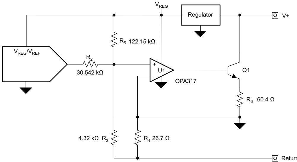
Figure 9-4. Loop Powered Transmitter Schematic
9.2.1.1 Design Requirements
The transmitter has only two external input pins; a supply connection and a ground (or return) connection. The transmitter communicates back to the host, typically a PLC analog input module, by precisely controlling the magnitude of the return current. To conform to the 4-mA to 20-mA communication standards, the complete transmitter must consume less than 4 mA of current.
The complete design of this circuit is outlined in TIPD158, Low Cost Loop-Powered 4-20mA Transmitter EMC/EMI Tested Reference Design. The design is expected to be low-cost and deliver immunity to the IEC61000-4 suite of tests with minimum impact on the accuracy of the system. Reference design TIPD158 includes the design goals, simulated results, and measured performance.
9.2.1.2 Detailed Design Procedure
Amplifier U1 uses negative feedback to make sure that the potentials at the inverting (V–) and noninverting (V+) input terminals are equal. In this configuration, V– is directly tied to the local GND; therefore, the potential at the noninverting input terminal is driven to local ground. Thus, the voltage difference across ${ \sf R } _ { 2 }$ is the DAC output voltage (VOUT), and the voltage difference across $\mathsf { R } _ { 5 }$ is the regulator voltage (VREG). These voltage differences cause currents to flow through $\mathsf { R } _ { 2 }$ and $\mathsf { R } _ { 5 } ,$ , as illustrated in Figure 9-5.
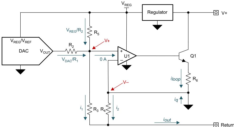
Figure 9-5. Voltage to Current Conversion
The currents from ${ \sf R } _ { 2 }$ and $\mathsf { R } _ { 5 }$ sum into $\mathfrak { i } _ { 1 }$ (defined in Equation 2), and $\mathsf { i } _ { 1 }$ flows through ${ \mathsf { R } } _ { 3 }$
$$
i _ {1} = \frac {V _ {\text { DAC }}}{R _ {2}} + \frac {V _ {\text { REG }}}{R _ {5}}\tag{2}
$$
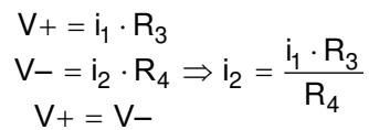
Amplifier U2 drives the base of Q1, the NPN bipolar junction transistor (BJT), to allow current to flow through $\mathsf { R } _ { 4 }$ so that the voltage drops across ${ \mathsf { R } } _ { 3 }$ and $\mathsf { R } _ { 4 }$ remain equal. This design keeps the inverting and noninverting terminals at the same potential. A small part of the current through $\mathsf { R } _ { 4 }$ is sourced by the quiescent current of all of the components used in the transmitter design (regulator, amplifier, and DAC). The voltage drops across ${ \mathsf { R } } _ { 3 }$ and $\mathsf { R } _ { 4 }$ are equal; therefore, different-sized resistors cause different current flow through each resistor. Use these different-sized resistors to apply gain to the current flow through $\mathsf { R } _ { 4 }$ by controlling the ratio of resistor ${ \mathsf { R } } _ { 3 }$ to $\mathsf { R } _ { 4 } ,$ , as shown in Equation 3:
$$
\begin{array}{c} \mathsf {V} _ {+} = \mathsf {i} _ {1} \cdot \mathsf {R} _ {3} \ \mathsf {V} _ {-} = \mathsf {i} _ {2} \cdot \mathsf {R} _ {4} \Rightarrow \mathsf {i} _ {2} = \frac {\mathsf {i} _ {1} \cdot \mathsf {R} _ {3}}{\mathsf {R} _ {4}} \ \mathsf {V} _ {+} = \mathsf {V} _ {-} \end{array}\tag{3}
$$
The current gain in the circuit helps allow a majority of the output current to come directly from the loop through Q1 instead of from the voltage-to-current converter. This current gain, in addition to the low-power components, keeps the current consumption of the voltage-to-current converter low. Currents $\mathfrak { i } _ { 1 }$ and $\mathsf { i } _ { 2 }$ sum to form output current ${ \dot { \mathsf { I } } } _ { \mathsf { O u t } } ,$ as shown in Equation 4:
$$
i _ {\text {out}} = i _ {1} + i _ {2} = \frac {V _ {\text {DAC}}}{R _ {2}} + \frac {V _ {\text {REG}}}{R _ {5}} + \frac {R _ {3}}{R _ {4}} \cdot \left(\frac {V _ {\text {DAC}}}{R _ {2}} + \frac {V _ {\text {REG}}}{R _ {5}}\right) = \left(\frac {V _ {\text {DAC}}}{R _ {2}} + \frac {V _ {\text {REG}}}{R _ {5}}\right) \cdot \left(1 + \frac {R _ {3}}{R _ {4}}\right)\tag{4}
$$
The complete transfer function, arranged as a function of input code, is shown in Equation 5. The remaining sections divide this circuit into blocks for simplified discussion.
$$
i _ {\text { out }} (\text { Code }) = \left(\frac {V _ {\text { REG }} \cdot \text { Code }}{2 ^ {\text { Resolution }} \cdot R _ {2}} + \frac {V _ {\text { REG }}}{R _ {5}}\right) \cdot \left(1 + \frac {R _ {3}}{R _ {4}}\right)\tag{5}
$$
Resistor $\mathsf { R } _ { 6 }$ is included to reduce the gain of transistor Q1, and therefore, reduce the closed-loop gain of the voltage-to-current converter for a stable design. Size resistors ${ \sf R } _ { 2 } , { \sf R } _ { 3 } , { \sf R } _ { 4 } ,$ and $\mathsf { R } _ { 5 }$ based on the full-scale range of the DAC, regulator voltage, and the desired current output range of the design.
9.2.1.3 Application Curves
Figure 9-6 shows the measured transfer function of the circuit. Figure 9-7 shows the total unadjusted error (TUE) of the circuit, staying below 0.15 %FSR.

Figure 9-6. Output Current vs Code

Figure 9-7. Current Total Unadjusted Error vs Code
9.2.2 Using the REF5050 as a Power Supply for the DACx311
As a result of the extremely low supply current required by the DACx311, an alternative option is to use a REF5050 5-V precision voltage reference to supply the required voltage to the part, as shown in Figure 9-8. This option is especially useful if the power supply is too noisy or if the system supply voltages are at some value other than 5 V. The REF5050 outputs a steady supply voltage for the DACx311. If the REF5050 is used, the current needed to supply DACx311 is typically 110 μA at 5 V, with no load on the output of the DAC. When the DAC output is loaded, the REF5050 also needs to supply the current to the load. The total current required (with a 5 kΩ load on the DAC output) is:
$$
1 1 0 \mu \mathrm{A} + (5 \mathrm{V} / 5 \mathrm{k} \Omega) = 1. 1 1 \mathrm{mA}\tag{6}
$$
The load regulation of the REF5050 is typically 0.002%/mA, which results in an error of 90 μV for the 1.1 mA current drawn from the device. This value corresponds to a 0.07 LSB error at 12 bits (DAC7311).
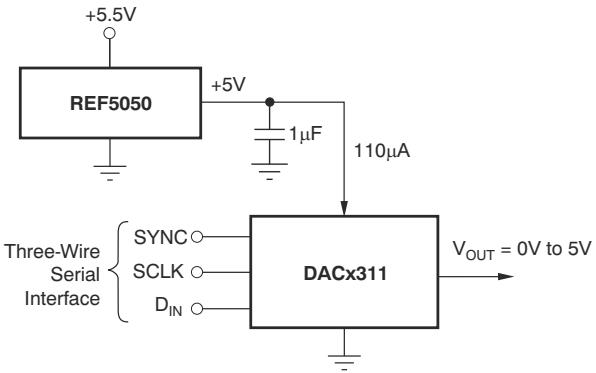
Figure 9-8. REF5050 as Power Supply to DACx311
For other power-supply voltages, alternative references such as the REF3030 (3 V), REF3033 (3.3 V), or REF3220 (2.048 V) are recommended. For a full list of available voltage references from TI, see the TI web site at www.ti.com.
9.2.3 Bipolar Operation Using the DACx311
The DACx311 has been designed for single-supply operation but a bipolar output range is also possible using the circuit in Figure 9-9. The circuit shown gives an output voltage range of ±5 V. Rail-to-rail operation at the amplifier output is achievable using an OPA211, OPA340, or OPA703 as the output amplifier. For a full list of available operational amplifiers from TI, see the TI web site at www.ti.com
The output voltage for any input code can be calculated as follows:
$$
V _ {O} = \left[ A V _ {D D} \times \left(\frac {D}{2 ^ {n}}\right) \times \left(\frac {R _ {1} + R _ {2}}{R _ {1}}\right) - A V _ {D D} \times \left(\frac {R _ {2}}{R _ {1}}\right) \right]\tag{7}
$$
where
• n = resolution in bits; either 8 (DAC5311), 10 (DAC6311), or 12 (DAC7311).
D = decimal equivalent of the binary code that is loaded to the DAC register. D ranges from 0 to 255 for 8-bit DAC5311, 0 to 1023 for the 10-bit DAC6311 and 0 to 4095 for the 12-bit DAC7311.
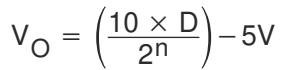
With $\mathsf { A V } _ { \mathsf { D D } } = 5 \mathsf { V } , \mathsf { R } _ { 1 } = \mathsf { R } _ { 2 } = 1 0 \mathsf { k } \Omega \mathrm { : }$
$$
V _ {O} = \left(\frac {1 0 \times D}{2 ^ {n}}\right) - 5 V\tag{8}
$$
The resulting output voltage range is ±5 V. Code 000h corresponds to a –5-V output and FFFh (12-bit level) corresponding to a +5-V output.

Figure 9-9. Bipolar Operation With the DACx311
9.3 Power Supply Recommendations
The DACx311 is designed to operate with a unipolar analog power supply ranging from 2.0 V to 5.5 V on the $\mathsf { A V } _ { \mathsf { D D } }$ pin. The $\mathsf { A V } _ { \mathsf { D D } }$ pin supplies power to the digital and analog circuits (including the resistor string) inside the DAC. The current consumption of this pin is specified in the Electrical Characteristics table. Use a 1 μF to 10 $\mu \mathsf { F }$ capacitor in parallel with a 0.1 μF bypass capacitor on this pin to remove high-frequency noise.
9.4 Layout
9.4.1 Layout Guidelines
A precision analog component requires careful layout, adequate bypassing, and clean, well-regulated power supplies.
The DACx311 offers single-supply operation, and is often used in close proximity to digital logic, microcontrollers, microprocessors, and digital signal processors. The more digital logic present in the design and the higher the switching speed, the more difficult the task is to achieve good performance from the converter.
As a result of the single ground pin of the DACx311, all return currents, including digital and analog return currents, must flow through the GND pin. Ideally, GND is connected directly to an analog ground plane. Separate this plane from the ground connection for the digital components until connected at the power entry point of the system.
The power applied to $\mathsf { A V } _ { \mathsf { D D } }$ must be well-regulated and low-noise. Switching power supplies and dc/dc converters often have high-frequency glitches or spikes riding on the output voltage. In addition, digital components can create similar high-frequency spikes as the internal logic switches state. This noise can easily couple into the DAC output voltage through various paths between the power connections and analog output. This condition is particularly true for the DACx311, as the power supply is also the reference voltage for the DAC.
As with the GND connection, connect $\mathsf { A V } _ { \mathsf { D D } }$ to a 5‑V power supply plane or trace that is separate from the connection for digital logic until connected at the power entry point. In addition, 1-μF to 10-μF and 0.1-μF bypass capacitors are strongly recommended. In some situations, additional bypassing can be required, such as a 100 μF electrolytic capacitor or even a Pi filter made up of inductors and capacitors—all designed to essentially low-pass filter the 5-V supply and remove high-frequency noise.
9.4.2 Layout Example

Figure 9-10. Recommended Layout
10 Device and Documentation Support
10.1 Receiving Notification of Documentation Updates
To receive notification of documentation updates, navigate to the device product folder on ti.com. Click on Subscribe to updates to register and receive a weekly digest of any product information that has changed. For change details, review the revision history included in any revised document.
10.2 Support Resources
TI E2E™ support forums are an engineer's go-to source for fast, verified answers and design help — straight from the experts. Search existing answers or ask your own question to get the quick design help you need.
Linked content is provided "AS IS" by the respective contributors. They do not constitute TI specifications and do not necessarily reflect TI's views; see TI's Terms of Use.
10.3 Trademarks
TI E2E™ is a trademark of Texas Instruments.
All trademarks are the property of their respective owners.
10.4 Electrostatic Discharge Caution

This integrated circuit can be damaged by ESD. Texas Instruments recommends that all integrated circuits be handled with appropriate precautions. Failure to observe proper handling and installation procedures can cause damage.
ESD damage can range from subtle performance degradation to complete device failure. Precision integrated circuits may be more susceptible to damage because very small parametric changes could cause the device not to meet its published specifications.
10.5 Glossary
TI Glossary This glossary lists and explains terms, acronyms, and definitions.
11 Mechanical, Packaging, and Orderable Information
The following pages include mechanical, packaging, and orderable information. This information is the most current data available for the designated devices. This data is subject to change without notice and revision of this document. For browser-based versions of this data sheet, refer to the left-hand navigation.
PACKAGING INFORMATION
| Orderable part number | Status(1) | Material type(2) | Package | Pins | Package qty | Carrier | RoHS(3) | Lead finish/ Ball material(4) | MSL rating/ Peak reflow(5) | Op temp (°C) | Part marking(6) |
| DAC5311IDCKR | Active | Production | SC70 (DCK) | 6 | 3000 | LARGE T&R | Yes | NIPDAU | Level-1-260C-UNLIM | -40 to 125 | D53 |
| DAC5311IDCKR.A | Active | Production | SC70 (DCK) | 6 | 3000 | LARGE T&R | Yes | NIPDAU | Level-1-260C-UNLIM | -40 to 125 | D53 |
| DAC5311IDCKRG4 | Active | Production | SC70 (DCK) | 6 | 3000 | LARGE T&R | Yes | NIPDAU | Level-1-260C-UNLIM | -40 to 125 | D53 |
| DAC5311IDCKRG4.A | Active | Production | SC70 (DCK) | 6 | 3000 | LARGE T&R | Yes | NIPDAU | Level-1-260C-UNLIM | -40 to 125 | D53 |
| DAC5311IDCKT | Active | Production | SC70 (DCK) | 6 | 250 | SMALL T&R | Yes | NIPDAU | Level-1-260C-UNLIM | -40 to 125 | D53 |
| DAC5311IDCKT.A | Active | Production | SC70 (DCK) | 6 | 250 | SMALL T&R | Yes | NIPDAU | Level-1-260C-UNLIM | -40 to 125 | D53 |
| DAC6311IDCKR | Active | Production | SC70 (DCK) | 6 | 3000 | LARGE T&R | Yes | NIPDAU | Level-1-260C-UNLIM | -40 to 125 | D63 |
| DAC6311IDCKR.A | Active | Production | SC70 (DCK) | 6 | 3000 | LARGE T&R | Yes | NIPDAU | Level-1-260C-UNLIM | -40 to 125 | D63 |
| DAC6311IDCKRG4 | Active | Production | SC70 (DCK) | 6 | 3000 | LARGE T&R | Yes | NIPDAU | Level-1-260C-UNLIM | -40 to 125 | D63 |
| DAC6311IDCKRG4.A | Active | Production | SC70 (DCK) | 6 | 3000 | LARGE T&R | Yes | NIPDAU | Level-1-260C-UNLIM | -40 to 125 | D63 |
| DAC6311IDCKT | Active | Production | SC70 (DCK) | 6 | 250 | SMALL T&R | Yes | NIPDAU | Level-1-260C-UNLIM | -40 to 125 | D63 |
| DAC6311IDCKT.A | Active | Production | SC70 (DCK) | 6 | 250 | SMALL T&R | Yes | NIPDAU | Level-1-260C-UNLIM | -40 to 125 | D63 |
| DAC6311IDCKTG4 | Active | Production | SC70 (DCK) | 6 | 250 | SMALL T&R | Yes | NIPDAU | Level-1-260C-UNLIM | -40 to 125 | D63 |
| DAC7311IDCKR | Active | Production | SC70 (DCK) | 6 | 3000 | LARGE T&R | Yes | NIPDAU | Level-1-260C-UNLIM | -40 to 125 | D73 |
| DAC7311IDCKR.A | Active | Production | SC70 (DCK) | 6 | 3000 | LARGE T&R | Yes | NIPDAU | Level-1-260C-UNLIM | -40 to 125 | D73 |
| DAC7311IDCKRG4 | Active | Production | SC70 (DCK) | 6 | 3000 | LARGE T&R | Yes | NIPDAU | Level-1-260C-UNLIM | -40 to 125 | D73 |
| DAC7311IDCKRG4.A | Active | Production | SC70 (DCK) | 6 | 3000 | LARGE T&R | Yes | NIPDAU | Level-1-260C-UNLIM | -40 to 125 | D73 |
| DAC7311IDCKT | Active | Production | SC70 (DCK) | 6 | 250 | SMALL T&R | Yes | NIPDAU | Level-1-260C-UNLIM | -40 to 125 | D73 |
| DAC7311IDCKT.A | Active | Production | SC70 (DCK) | 6 | 250 | SMALL T&R | Yes | NIPDAU | Level-1-260C-UNLIM | -40 to 125 | D73 |
| DAC7311IDCKTG4 | Active | Production | SC70 (DCK) | 6 | 250 | SMALL T&R | Yes | NIPDAU | Level-1-260C-UNLIM | -40 to 125 | D73 |
(1) Status: For more details on status, see our product life cycle.
(4) Lead finish/Ball material: Parts may have multiple material finish options. Finish options are separated by a vertical ruled line. Lead finish/Ball material values may wrap to two lines if the finish value exceeds the maximum column width.
(5) MSL rating/Peak reflow: The moisture sensitivity level ratings and peak solder (reflow) temperatures. In the event that a part has multiple moisture sensitivity ratings, only the lowest level per JEDEC standards is shown. Refer to the shipping label for the actual reflow temperature that will be used to mount the part to the printed circuit board.
(6) Part marking: There may be an additional marking, which relates to the logo, the lot trace code information, or the environmental category of the part.
Multiple part markings will be inside parentheses. Only one part marking contained in parentheses and separated by a "~" will appear on a part. If a line is indented then it is a continuation of the previous line and the tw combined represent the entire part marking for that device
Important Information and Disclaimer:The information provided on this page represents TI's knowledge and belief as of the date that it is provided. TI bases its knowledge and belief on information provided by third parties, and makes no representation or warranty as to the accuracy of such information. Efforts are underway to better integrate information from third parties. TI has taken and continues to take reasonable steps to provide representativ and accurate information but may not have conducted destructive testing or chemical analysis on incoming materials and chemicals. TI and TI suppliers consider certain information to be proprietary, and thus CAS number and other limited information may not be available for release.
In no event shall TI's liability arising out of such information exceed the total purchase price of the TI part(s) at issue in this document sold by TI to Customer on an annual basis.
OTHER QUALIFIED VERSIONS OF DAC5311 :
Automotive : DAC5311-Q1
NOTE: Qualified Version Definitions:
Automotive - Q100 devices qualified for high-reliability automotive applications targeting zero defects
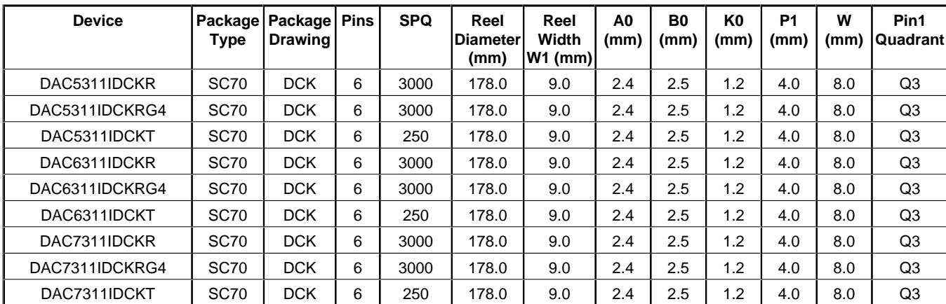
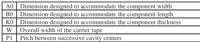
TAPE AND REEL INFORMATION

| A0 | Dimension designed to accommodate the component width |
| B0 | Dimension designed to accommodate the component length |
| K0 | Dimension designed to accommodate the component thickness |
| W | Overall width of the carrier tape |
| P1 | Pitch between successive cavity centers |
Reel Width (W1)
QUADRANT ASSIGNMENTS FOR PIN 1 ORIENTATION IN TAPE
*All dimensions are nomina
| Device | Package Type | Package Drawing | Pins | SPQ | Reel Diameter (mm) | Reel Width W1 (mm) | A0 (mm) | B0 (mm) | K0 (mm) | P1 (mm) | W (mm) | Pin1 Quadrant |
| DAC5311IDCKR | SC70 | DCK | 6 | 3000 | 178.0 | 9.0 | 2.4 | 2.5 | 1.2 | 4.0 | 8.0 | Q3 |
| DAC5311IDCKRG4 | SC70 | DCK | 6 | 3000 | 178.0 | 9.0 | 2.4 | 2.5 | 1.2 | 4.0 | 8.0 | Q3 |
| DAC5311IDCKT | SC70 | DCK | 6 | 250 | 178.0 | 9.0 | 2.4 | 2.5 | 1.2 | 4.0 | 8.0 | Q3 |
| DAC6311IDCKR | SC70 | DCK | 6 | 3000 | 178.0 | 9.0 | 2.4 | 2.5 | 1.2 | 4.0 | 8.0 | Q3 |
| DAC6311IDCKRG4 | SC70 | DCK | 6 | 3000 | 178.0 | 9.0 | 2.4 | 2.5 | 1.2 | 4.0 | 8.0 | Q3 |
| DAC6311IDCKT | SC70 | DCK | 6 | 250 | 178.0 | 9.0 | 2.4 | 2.5 | 1.2 | 4.0 | 8.0 | Q3 |
| DAC7311IDCKR | SC70 | DCK | 6 | 3000 | 178.0 | 9.0 | 2.4 | 2.5 | 1.2 | 4.0 | 8.0 | Q3 |
| DAC7311IDCKRG4 | SC70 | DCK | 6 | 3000 | 178.0 | 9.0 | 2.4 | 2.5 | 1.2 | 4.0 | 8.0 | Q3 |
| DAC7311IDCKT | SC70 | DCK | 6 | 250 | 178.0 | 9.0 | 2.4 | 2.5 | 1.2 | 4.0 | 8.0 | Q3 |
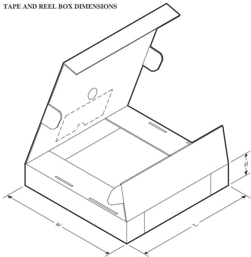
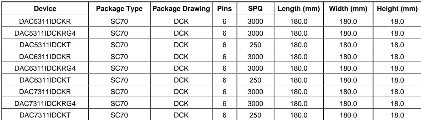
*All dimensions are nominal
| Device | Package Type | Package Drawing | Pins | SPQ | Length (mm) | Width (mm) | Height (mm) |
| DAC5311IDCKR | SC70 | DCK | 6 | 3000 | 180.0 | 180.0 | 18.0 |
| DAC5311IDCKRG4 | SC70 | DCK | 6 | 3000 | 180.0 | 180.0 | 18.0 |
| DAC5311IDCKT | SC70 | DCK | 6 | 250 | 180.0 | 180.0 | 18.0 |
| DAC6311IDCKR | SC70 | DCK | 6 | 3000 | 180.0 | 180.0 | 18.0 |
| DAC6311IDCKRG4 | SC70 | DCK | 6 | 3000 | 180.0 | 180.0 | 18.0 |
| DAC6311IDCKT | SC70 | DCK | 6 | 250 | 180.0 | 180.0 | 18.0 |
| DAC7311IDCKR | SC70 | DCK | 6 | 3000 | 180.0 | 180.0 | 18.0 |
| DAC7311IDCKRG4 | SC70 | DCK | 6 | 3000 | 180.0 | 180.0 | 18.0 |
| DAC7311IDCKT | SC70 | DCK | 6 | 250 | 180.0 | 180.0 | 18.0 |
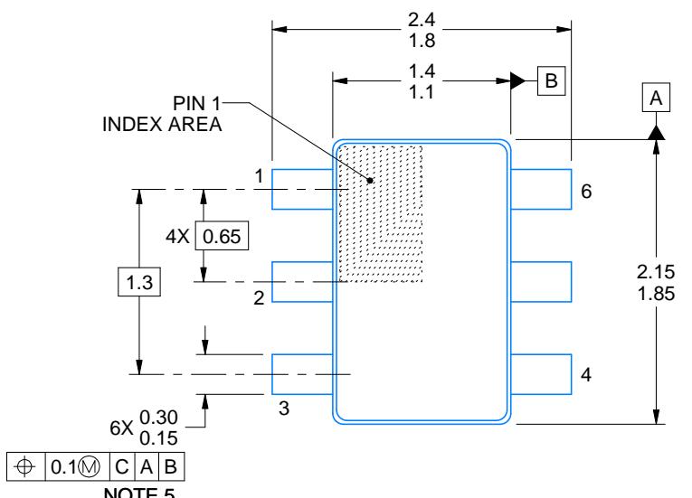
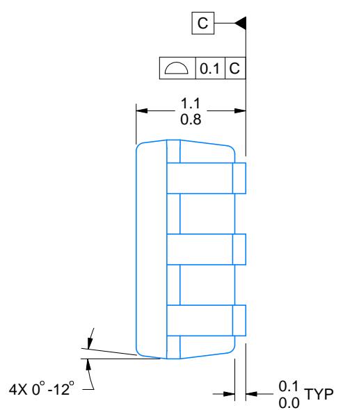
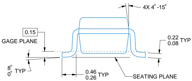
NOTES:
4214835/D 11/2024
All linear dimensions are in millimeters. Any dimensions in parenthesis are for reference only. Dimensioning and tolerancing per ASME Y14.5M.
This drawing is subject to change without notice.
SMALL OUTLINE TRANSISTOR

NOTES: (continued)
Publication IPC-7351 may have alternate designs.
Solder mask tolerances between and around signal pads can vary based on board fabrication site.
SMALL OUTLINE TRANSISTOR

SOLDER PASTE EXAMPLE BASED ON 0.125 THICK STENCIL SCALE:18X
4214835/D 11/2024
NOTES: (continued)
Laser cutting apertures with trapezoidal walls and rounded corners may offer better paste release. IPC-7525 may have alternate design recommendations.
Board assembly site may have different recommendations for stencil design.
Figures and diagrams from the PDF
Preview the extracted datasheet assets and open any image in a separate tab for closer inspection.






Use this datasheet from any agent
Send the page, markdown, chunks, or search endpoint to ChatGPT, Claude, embedr-app, or your own tooling.