
Amphenol RF 031-5431-10RFX BNC right-angle PCB receptacle jack
Right-angle BNC receptacle jack for PCB through-hole mounting and rear bulkhead panel mounting.
Amphenol 31-5431-10RFX customer outline drawing — BNC R/A PC mount receptacle jack
Source: Amphenol Corporation customer outline drawing 31-5431-10RFX, revision D (title "BNC R/A PC MOUNT RECEPTACLE JACK", code ID 74868, sheet 2 of 2, third-angle projection; rev A released 3/7/02, rev D 1/13/15 "removed border around PCB layout"). Distributor-hosted copy of the Amphenol PDF (it includes a Mouser cover page that lists 031-5431-10RFX).
Applicability: Amphenol RF publishes the same attributes for 031-5431 and 031-5431-10RFX: gold contact finish, phosphor-bronze contact, nickel-plated zinc die-cast body, polypropylene insulator, isolated = No, 1 GHz max, -40 to +85 C, post length 0.120 in (3.05 mm), bulkhead rear mount, PCB through-hole. The isolated variant 031-5431-1010 is a different part. Unless otherwise stated, dimensions are mm [inch] and marked REF. Tolerances are ±0.2 mm for 0.5–6 mm, ±0.4 mm for 6–30 mm and ±0.6 mm for 30–120 mm.
Notes (materials of construction)
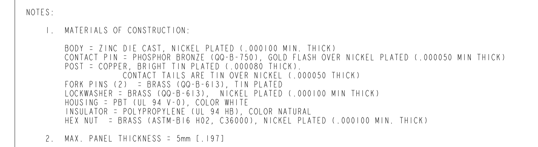
- Materials of construction:
- Body: zinc die cast, nickel plated (.000100 min. thick)
- Contact pin: phosphor bronze (QQ-B-750), gold flash over nickel plated (.000050 min thick)
- Post: copper, bright tin plated (.000080 thick); contact tails are tin over nickel (.000050 thick)
- Fork pins (2): brass (QQ-B-613), tin plated
- Lockwasher: brass (QQ-B-613), nickel plated (.000100 min thick)
- Housing: PBT (UL 94 V-0), color white
- Insulator: polypropylene (UL 94 HB), color natural
- Hex nut: brass (ASTM-B16 H02, C36000), nickel plated (.000100 min. thick)
- Maximum panel thickness = 5 mm [.197].
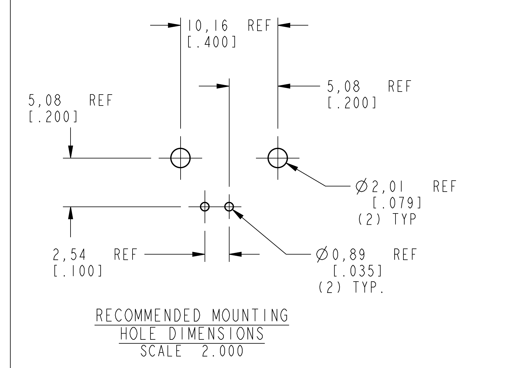
Recommended PCB mounting hole dimensions (scale 2:1)
| Feature | Value |
|---|---|
| Fork-pin holes | 2 × Ø2.01 mm [.079] REF |
| Fork-pin hole spacing | 10.16 mm [.400] REF (5.08 mm [.200] each side of the centre-contact hole line) |
| Contact holes (centre contact and ground post) | 2 × Ø0.89 mm [.035] REF |
| Contact hole spacing | 2.54 mm [.100] REF; the centre-contact hole is on the connector axis |
| Row offset | 5.08 mm [.200] REF between the fork-pin row and the contact-hole row (the fork-pin row is nearer the panel) |
Recommended panel mounting hole (scale 2:1)
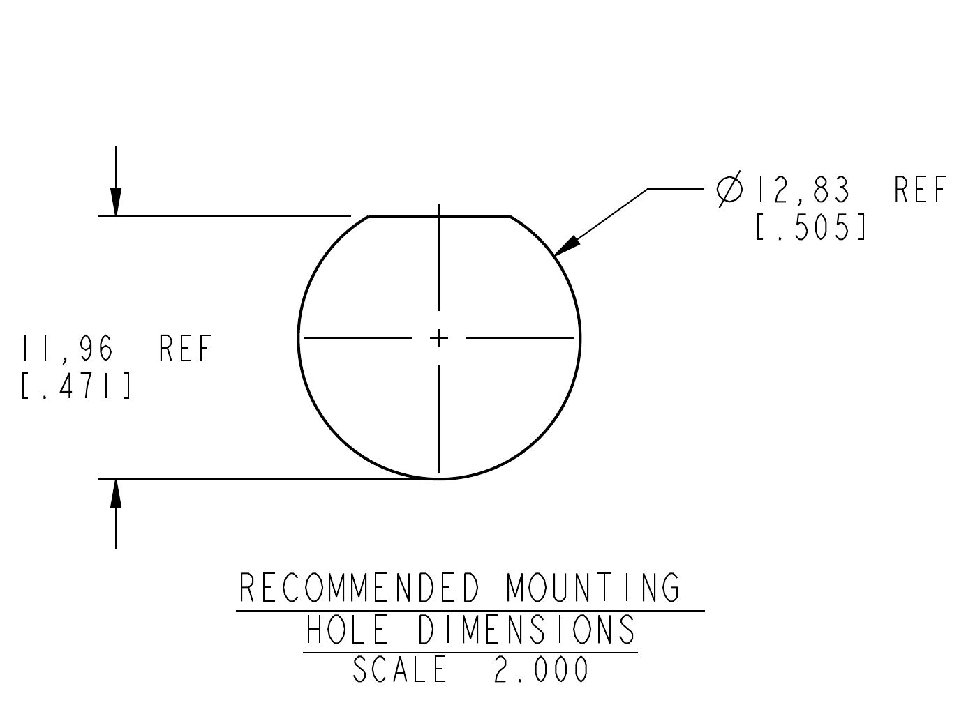
D-shaped panel hole: Ø12.83 mm [.505] REF with a flat at 11.96 mm [.471] REF.
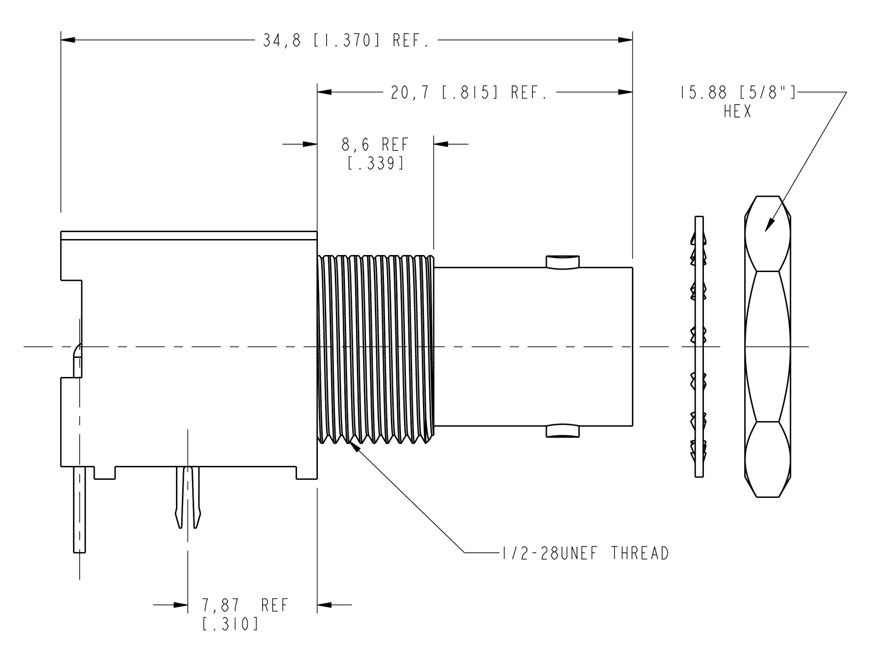
Side view
| Dimension | Value |
|---|---|
| Overall length | 34.8 mm [1.370] REF |
| Projection from body front face (panel side) | 20.7 mm [.815] REF |
| Threaded bushing length | 8.6 mm [.339] REF; thread 1/2-28 UNEF |
| Fork pins to body front face | 7.87 mm [.310] REF |
| Hex nut | 15.88 mm [5/8 in] across flats |
Rear (end) view
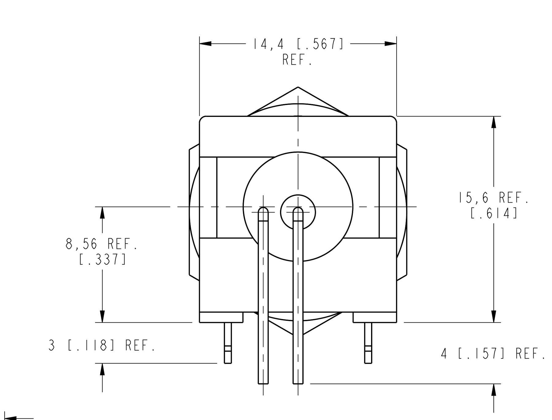
| Dimension | Value |
|---|---|
| Body width | 14.4 mm [.567] REF |
| Body height above seating plane | 15.6 mm [.614] REF |
| Connector axis above seating plane | 8.56 mm [.337] REF |
| Fork pin length below seating plane | 3 mm [.118] REF |
| Contact tail length below seating plane | 4 mm [.157] REF |
Figures and diagrams from the PDF
Preview the extracted datasheet assets and open any image in a separate tab for closer inspection.
Use this datasheet from any agent
Send the page, markdown, chunks, or search endpoint to ChatGPT, Claude, embedr-app, or your own tooling.