
JST B4P-VH-B 4-Position VH Locking Fan Header
4-position JST VH 3.96 mm through-hole locking wire-to-board header mapped for a 12 V PWM blower harness: GND, VIN_FAN, TACH, and PWM.
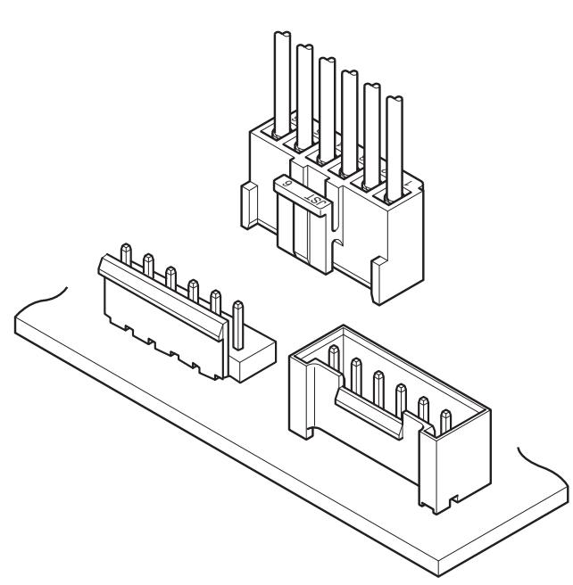
This wire-to-board connector with a 3.96 mm pitch is commonly used in power supply circuits for a wide variety of electrical and electronic devices. It supports currents up to 10 A.
・ Compact size, high current capability Compact design with a mounting height of 16.5 mm and a depth of 10.5 mm (for top-entry type), combined with a high current rating of 10 A (when using AWG #16 wire).
・Box-shaped leaf spring contact The contact is highly reliable, featuring a leafshaped design with excellent spring characteristics housed within a box.
・Secure lock mechanism
The large, highly visible outer-type housing with a strong lock ensures easy and secure insertion and removal. Additionally, it offers excellent mechanical reliability in the mated condition.
Specifications
・ Current rating: 10 A AC/DC
*When using AWG #16 with the standard type header. 7A AC/DC
*When using AWG #18 with the shrouded type header.
Note: Do not branch in parallel current which exceeds the rated current. If branched in parallel, current imbalance or other problems may occur. If it is absolutely necessary to branch such a large current in parallel, design the circuits without causing any imbalance and provide extra margin for each circuit.
・Voltage rating: 250 V AC/DC
・Temperature range: -40℃ to +105℃ (including temperature rise in applying electrical current)
・Contact resistance: Initial value/ 10 mΩ max.
After test/ 20 mΩ max.
・Insulation resistance: 1,000 MΩ min.
・Withstanding voltage: There shall be no breakdown or flashover while applying 1,500 VAC for one minute.
・Applicable wire range: Conductor size/ AWG #22 to AWG #16 Insulation O.D./ φ 1.7 mm to φ 3.0 mm
・Applicable PC board thickness: 1.6 mm
* Please refer to the "Handling Precautions for Terminals and Connectors" on our website (listed in the “Technical Documents” column on the Product Information page) before use.
* RoHS2 compliance
* Dimensional unit: mm
* Contact JST for details.
■ Standards
For information on overseas standard registrations, please refer to the "List of Registered Overseas Standards" on our website (listed in the “Technical Documents” column on the Product Information page).
* Specifications registered to overseas standards may differ from the general specifications listed above.
Housing
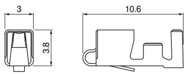
Contact
| Model No. | Applicable wire range | Q'ty/reel | |
| Conductor size AWG (mm2) | Insulation O.D. (mm) | ||
| SVH-21T-P1.1 | #22 to #18 (0.33 to 0.83) | 1.7 to 3.0 | 4,500 |
| SVH-41T-P1.1 | #20 to #16 (0.5 to 1.25) | 1.7 to 3.0 | 3,500 |
Material and Surface finish, etc.
Copper alloy, tin-plated
Note: When using the retainer mountable type housing, the applicable wire insulation outer diameter is φ 1.7 to φ 2.2.
Crimping machine
| Contact | Crimping machine | Applicator | Crimp applicator with dies |
| SVH-21T-P1.1 | AP-K2N | MKS-L | APLMK SVH21-11 |
| SVH-41T-P1.1 | APLMK SVH41-11 |
Note: Contact JST for fully automatic crimping applicator.
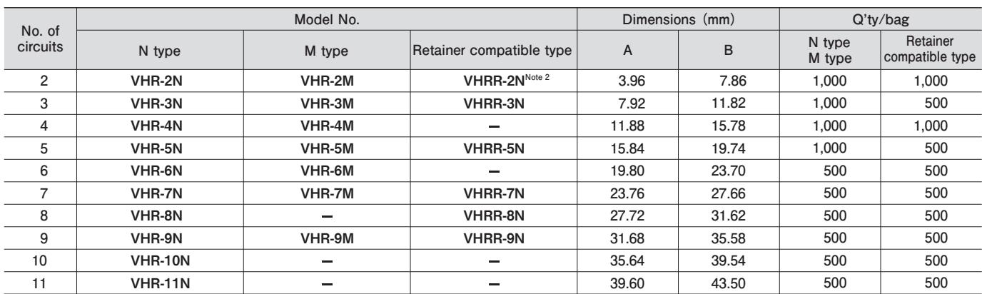
| No. of circuits | Model No. | Dimensions (mm) | Q'ty/bag | ||||
| N type | M type | Retainer compatible type | A | B | N type M type | Retainer compatible type | |
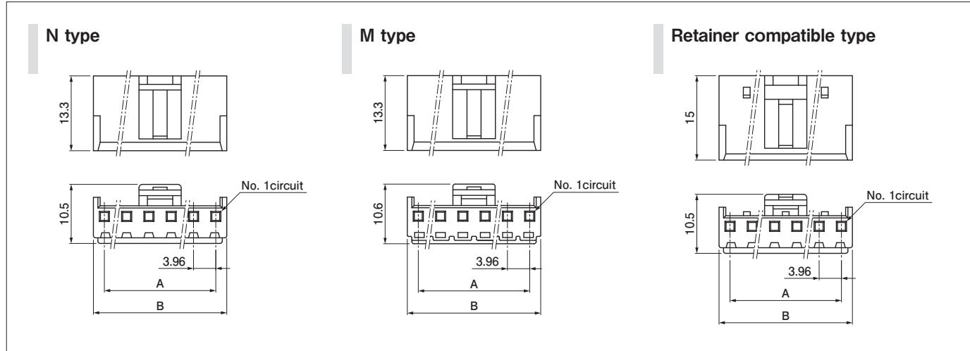
| 2 | VHR-2N | VHR-2M | $VHRR-2N^{Note 2}$ | 3.96 | 7.86 | 1,000 | 1,000 |
| 3 | VHR-3N | VHR-3M | VHRR-3N | 7.92 | 11.82 | 1,000 | 500 |
| 4 | VHR-4N | VHR-4M | — | 11.88 | 15.78 | 1,000 | 1,000 |
| 5 | VHR-5N | VHR-5M | VHRR-5N | 15.84 | 19.74 | 1,000 | 500 |
| 6 | VHR-6N | VHR-6M | — | 19.80 | 23.70 | 500 | 500 |
| 7 | VHR-7N | VHR-7M | VHRR-7N | 23.76 | 27.66 | 500 | 500 |
| 8 | VHR-8N | — | VHRR-8N | 27.72 | 31.62 | 500 | 500 |
| 9 | VHR-9N | VHR-9M | VHRR-9N | 31.68 | 35.58 | 500 | 500 |
| 10 | VHR-10N | — | — | 35.64 | 39.54 | 500 | 500 |
| 11 | VHR-11N | — | — | 39.60 | 43.50 | 500 | 500 |
Material and Surface finish, etc.
PA, natural (white)
Note: 1. With the M type, the exposed contact lances from the N type are covered by resin which is integrally formed and molded into the housing body as a single unit, further improving electrical safety.
2. Please note that the retainer mountable type housing for 2 circuits can only be used with the standard type header. It cannot be used with the shrouded type header.
3. For flame retardant grade of resin material used, please refer to the "List of Registered Overseas Standards" on our website (listed in the “Technical Documents” column on the Product Information page).
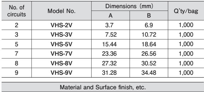
Retainer
| No. of circuits | Model No. | Dimensions (mm) | Q'ty/bag | |
| A | B | |||
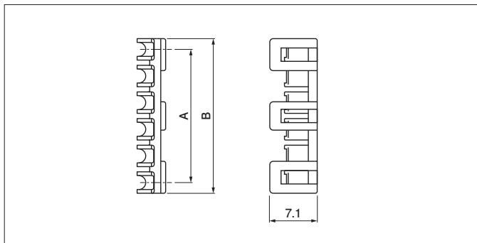
| 2 | VHS-2V | 3.7 | 6.9 | 1,000 |
| 3 | VHS-3V | 7.52 | 10.72 | 1,000 |
| 5 | VHS-5V | 15.44 | 18.64 | 1,000 |
| 7 | VHS-7V | 23.36 | 26.56 | 1,000 |
| 8 | VHS-8V | 27.32 | 30.52 | 1,000 |
| 9 | VHS-9V | 31.28 | 34.48 | 1,000 |
| Material and Surface finish, etc. | ||||
PA (GF), natural (ivory)
Note: For flame retardant grade of resin material used, please refer to the "List of Registered Overseas Standards" on our website (listed in the "Technical Documents" column on the Product Information page).
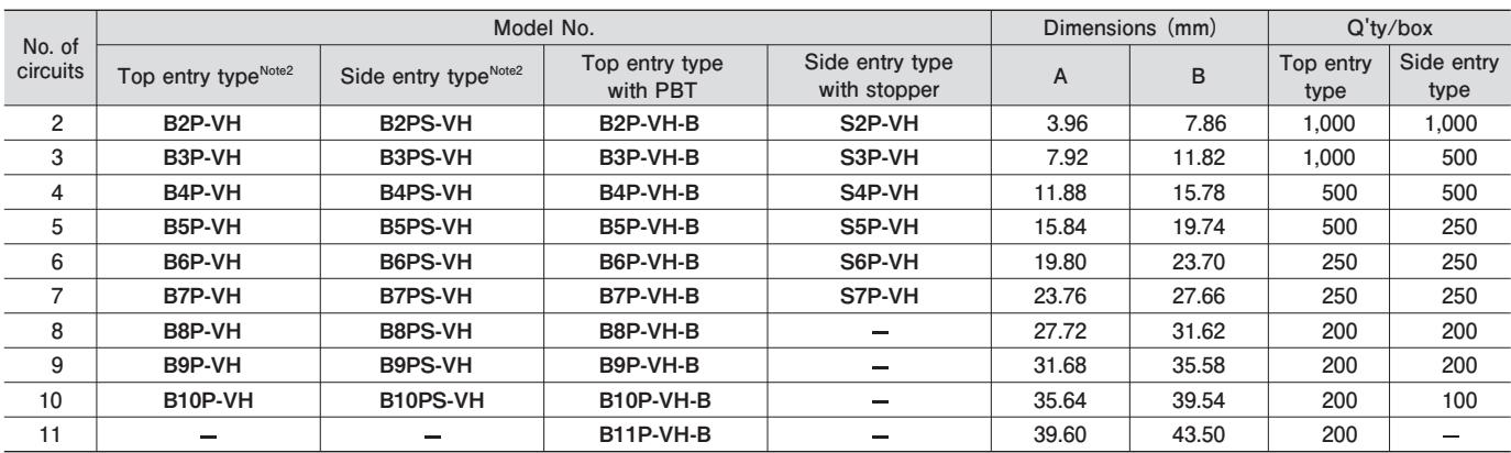
Header (Standard type)
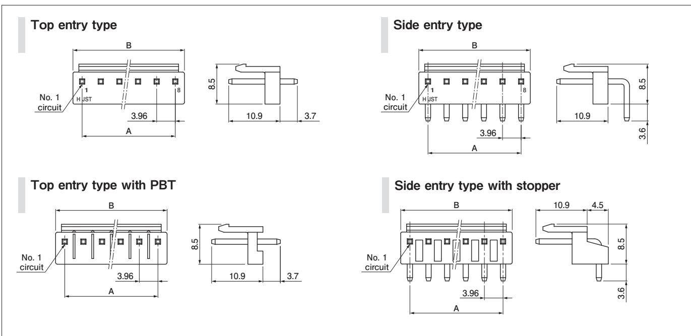
| No. of circuits | Model No. | Dimensions (mm) | Q'ty/box | |||||
| $Top\ entry\ type^{Note2}$ | $Side\ entry\ type^{Note2}$ | Top entry type with PBT | Side entry type with stopper | A | B | Top entry type | Side entry type | |
| 2 | B2P-VH | B2PS-VH | B2P-VH-B | S2P-VH | 3.96 | 7.86 | 1,000 | 1,000 |
| 3 | B3P-VH | B3PS-VH | B3P-VH-B | S3P-VH | 7.92 | 11.82 | 1,000 | 500 |
| 4 | B4P-VH | B4PS-VH | B4P-VH-B | S4P-VH | 11.88 | 15.78 | 500 | 500 |
| 5 | B5P-VH | B5PS-VH | B5P-VH-B | S5P-VH | 15.84 | 19.74 | 500 | 250 |
| 6 | B6P-VH | B6PS-VH | B6P-VH-B | S6P-VH | 19.80 | 23.70 | 250 | 250 |
| 7 | B7P-VH | B7PS-VH | B7P-VH-B | S7P-VH | 23.76 | 27.66 | 250 | 250 |
| 8 | B8P-VH | B8PS-VH | B8P-VH-B | - | 27.72 | 31.62 | 200 | 200 |
| 9 | B9P-VH | B9PS-VH | B9P-VH-B | - | 31.68 | 35.58 | 200 | 200 |
| 10 | B10P-VH | B10PS-VH | B10P-VH-B | - | 35.64 | 39.54 | 200 | 100 |
| 11 | - | - | B11P-VH-B | - | 39.60 | 43.50 | 200 | - |
Material and Surface finish, etc.
Post: Copper alloy, tin-plated Base housing: Non-PBT/ PA, natural (white) PBT/ PBT (GF), natural (white)
Note: 1. This product displays (LF)(SN) on a label.
Headers with posts omitted are also available. Please contact JST for further details.
For flame retardant grade of resin material used, please refer to the "List of Registered Overseas Standards" on our website (listed in the “Technical Documents” column on the Product Information page).
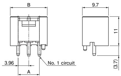
Header (Shrouded Header)
<2, 3 circuits>
<4 to 10 circuits>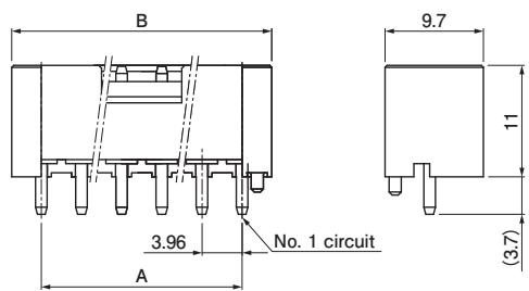
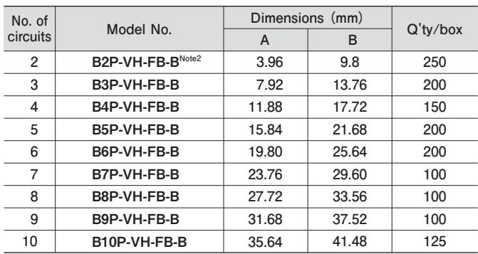
| No. of circuits | Model No. | Dimensions (mm) | Q'ty/box | |
| A | B | |||
| 2 | $B2P-VH-FB-B^{Note2}$ | 3.96 | 9.8 | 250 |
| 3 | B3P-VH-FB-B | 7.92 | 13.76 | 200 |
| 4 | B4P-VH-FB-B | 11.88 | 17.72 | 150 |
| 5 | B5P-VH-FB-B | 15.84 | 21.68 | 200 |
| 6 | B6P-VH-FB-B | 19.80 | 25.64 | 200 |
| 7 | B7P-VH-FB-B | 23.76 | 29.60 | 100 |
| 8 | B8P-VH-FB-B | 27.72 | 33.56 | 100 |
| 9 | B9P-VH-FB-B | 31.68 | 37.52 | 100 |
| 10 | B10P-VH-FB-B | 35.64 | 41.48 | 125 |
Material and Surface finish, etc.
Post: Copper alloy, tin-plated
Base housing: PBT (GF), natural (white)
Note: 1. This product displays (LF)(SN) on a label.
- The housings that mate with the two position are the N-type and M-type.
Please note that retainer mountable type cannot be used.
- For flame retardant grade of resin material used, please refer to the "List of Registered Overseas Standards" on our website (listed in the "Technical Documents" column on the Product Information page).
PC board layout and Assembly layout
Top entry type
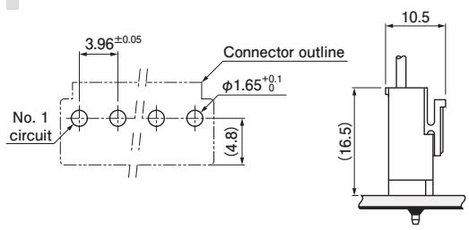
Side entry type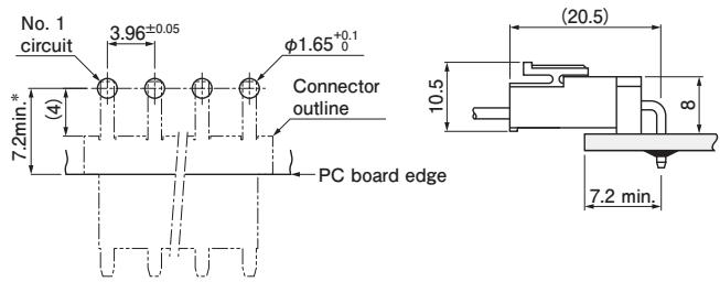
*11.0 max when used with the VR connector socket
Side entry type with stopper
Shrouded Header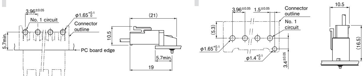
Note: 1. The PC board layout figure shown is viewed from the connector mounting surface.
Tolerance for the PCB hole pitch shall be ± 0.05 and shall not accumulate.
Hole dimensions differ depending on the type of PCB and PCB drilling method. The above dimensions are for reference only. Please contact JST for further detail
The assembly layout is for N-type housings.
For housings other than N-type, please contact JST.
Model number allocation
Contact
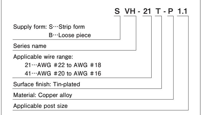
Series name
Applicable wire range:
21…AWG #22 to AWG #18
41…AWG #20 to AWG #16
Surface finish: Tin-plated
Material: Copper alloy
Applicable post size
Housing/ N type, M type
VH R - - 2 N
Series name
Type: For receptacle contact
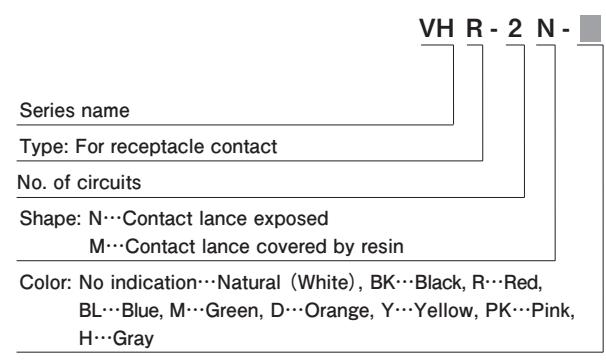
No. of circuits
Shape: N…Contact lance exposed M…Contact lance covered by resin
Color: No indication…Natural (White), BK…Black, R…Red, BL…Blue, M…Green, D…Orange, Y…Yellow, PK…Pink, H…Gray
Housing/ Retainer compatible type
VH R R - - 2 N
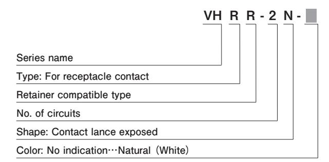
Series name
Type: For receptacle contact
Retainer compatible type
No. of circuits
Shape: Contact lance exposed
Color: No indication…Natural (White)
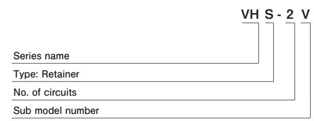
Type: Retainer
No. of circuits
Header (Standard type)
Retainer
B 2P
Sub model number
Series name
Assembly product
No. of circuits
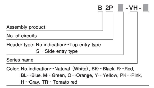
Series name
H…Gray, TR…Tomato red
VH S - 2 V
Color: No indication…Natural (White), BK…Black, R…Red,
Header type: No indication…Top entry type S…Side entry type
Header (Standard type)/ Side entry type with stopper
Header type: Side entry type with stopper
No. of circuits
Series name
Color: No indication…Natural (White), BK…Black,
Red, BL…Blue, M…Green, Y…Yellow
Header (Standard type)/ Top entry type with PBT
B -2P VH B --
Assembly product
No. of circuits
Series name
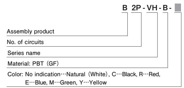
Material: PBT (GF)
Color: No indication…Natural (White), C…Black, R…Red, E…Blue, M…Green, Y…Yellow
Header (Shrouded Header)
B - 2P VH FB B - - -
Assembly product
No. of circuits
Series name
Sub model numbe
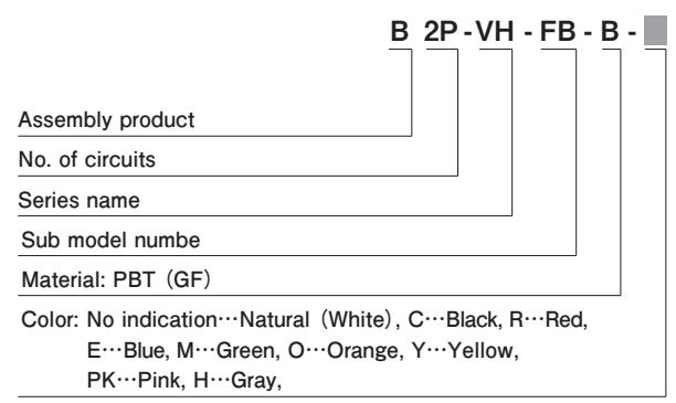
Material: PBT (GF)
Color: No indication…Natural (White), C…Black, R…Red, E…Blue, M…Green, O…Orange, Y…Yellow, PK…Pink, H…Gray,
Model number allocation
Headers with posts omitted (standard type)
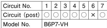
1) Polarized header (N-1) with post omitted However, this only applies when 4 posts or more are used
Example)

| Circuit No. | 1 | 2 | 3 | 4 | 5 | 6 | 7 |
| Circuit (post) | ○ | ○ | ○ | ○ | ○ | × | ○ |
| Model No. | B6P7-VH | ||||||
○: with post ×: without post
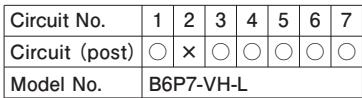
2) Polarized header with circuit No. 2 post omitted However, this only applies when 4 posts or more are used
Example)
| Circuit No. | 1 | 2 | 3 | 4 | 5 | 6 | 7 |
| Circuit (post) | ○ | × | ○ | ○ | ○ | ○ | ○ |
| Model No. | B6P7-VH-L | ||||||

○: with post ×: without post
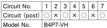
3) Header with pitch size doubled by omitting even numbered posts However, this only applies if the total number of circuits (including circuits without posts) is an odd number.
①Header with pitch size doubled (7.92 mm)
B*1P*2 -VH
Example)
| Circuit No. | 1 | 2 | 3 | 4 | 5 | 6 | 7 |
| Circuit (post) | ○ | × | ○ | × | ○ | × | ○ |
| Model No. | B4P7-VH | ||||||
○: with post ×: without post
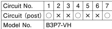
②Header with pitch size tripled (11.88 mm)
B*1P*2-VH
Example)
| Circuit No. | 1 | 2 | 3 | 4 | 5 | 6 | 7 |
| Circuit (post) | ○ | × | × | ○ | × | × | ○ |
| Model No. | B3P7-VH | ||||||
○: with post ×: without post
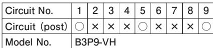
③Header with pitch size quadrupled (15.84 mm)

Example)
| Circuit No. | 1 | 2 | 3 | 4 | 5 | 6 | 7 | 8 | 9 |
| Circuit (post) | ○ | × | × | × | ○ | × | × | × | ○ |
| Model No. | B3P9-VH | ||||||||
○: with post ×: without post
Note) *1: Actual number of circuits (actual number of posts) *2: Total number of circuits (including post-omitted circuits)
Figures and diagrams from the PDF
Preview the extracted datasheet assets and open any image in a separate tab for closer inspection.


Use this datasheet from any agent
Send the page, markdown, chunks, or search endpoint to ChatGPT, Claude, embedr-app, or your own tooling.