
SH Connector 4-Circuit Top-Entry SMT Header
1.0 mm pitch wire-to-board crimp-style top-entry SMT header with 4 circuits.
JST SH Connector (eSH.pdf) — BM04B-SRSS-TB top-entry header
Transcription of the JST SH connector catalog (https://www.jst-mfg.com/product/pdf/eng/eSH.pdf, 4 pages, SHA-256 ea3071ca5ee5a6069eba534fa39a10f34c9fb742ee42135a69ab4156bfa0f5de). The publisher's PDF is owner-password protected, so the parser could not process it. This text was transcribed from the PDF's text layer and checked against the rendered pages, which are included below. Dimensional unit: mm. The figures are the authoritative drawings.
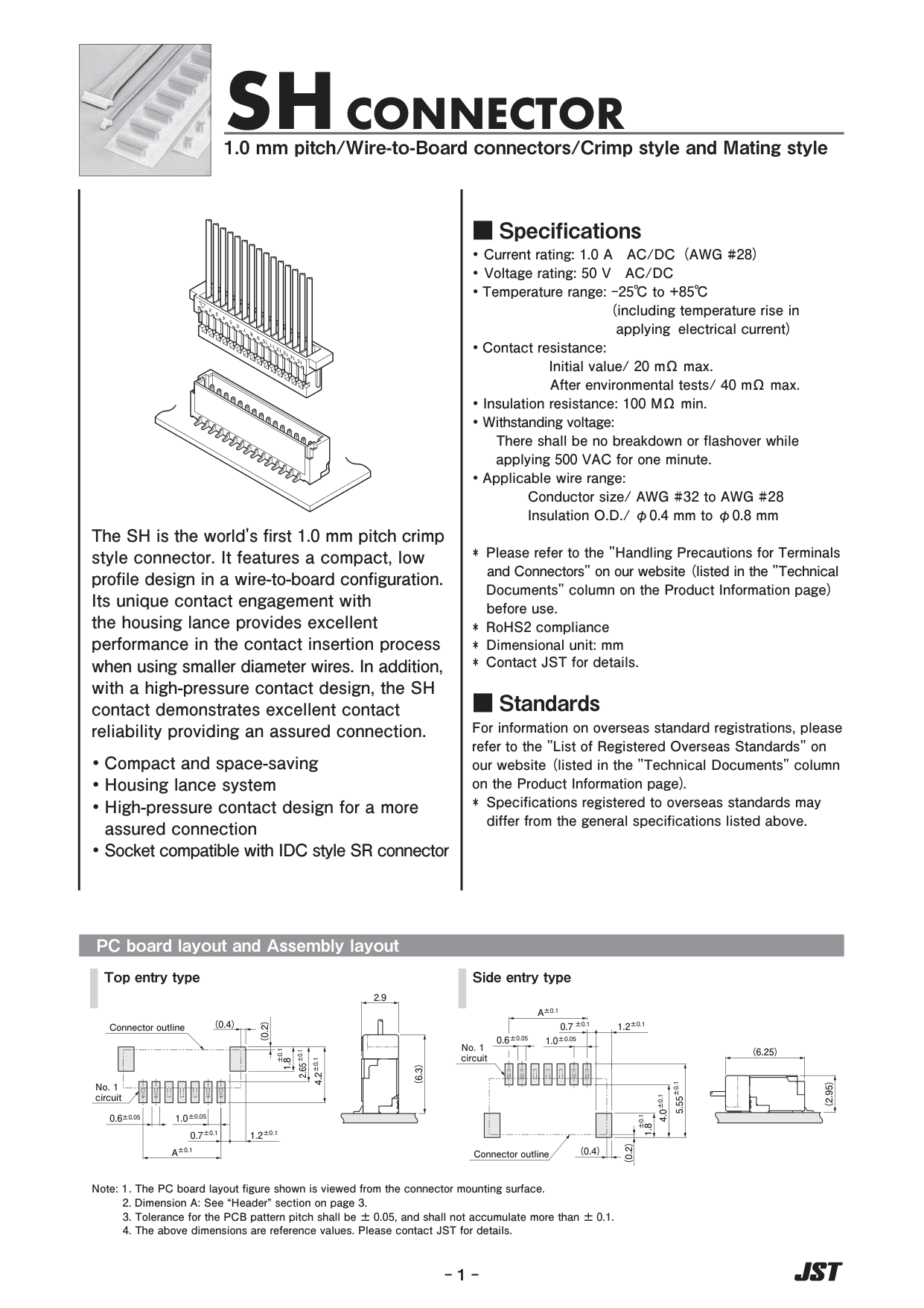
Page 1 — Overview, specifications, PC board layout
SH CONNECTOR: 1.0 mm pitch / Wire-to-Board connectors / Crimp style and Mating style.
The SH is the world's first 1.0 mm pitch crimp style connector. It features a compact, low profile design in a wire-to-board configuration. Its unique contact engagement with the housing lance provides excellent performance in the contact insertion process when using smaller diameter wires. In addition, with a high-pressure contact design, the SH contact demonstrates excellent contact reliability providing an assured connection.
- Compact and space-saving
- Housing lance system
- High-pressure contact design for a more assured connection
- Socket compatible with IDC style SR connector
Specifications
| Item | Value |
|---|---|
| Current rating | 1.0 A AC/DC (AWG #28) |
| Voltage rating | 50 V AC/DC |
| Temperature range | -25 C to +85 C (including temperature rise in applying electrical current) |
| Contact resistance | Initial value 20 mOhm max.; after environmental tests 40 mOhm max. |
| Insulation resistance | 100 MOhm min. |
| Withstanding voltage | No breakdown or flashover while applying 500 VAC for one minute |
| Applicable wire | Conductor size AWG #32 to AWG #28; insulation O.D. 0.4 mm to 0.8 mm |
Notes on page 1: refer to JST "Handling Precautions for Terminals and Connectors" before use; RoHS2 compliance; dimensional unit mm; contact JST for details. For overseas standard registrations, see the JST "List of Registered Overseas Standards" (specifications registered to overseas standards may differ).
PC board layout and Assembly layout — Top entry type (BM type)
Viewed from the connector mounting surface. A is from the header table on page 3; for BM04B-SRSS-TB, A = 3.0.
| Dimension | Value |
|---|---|
| Signal pad width | 0.6 +/-0.05 |
| Signal pad pitch | 1.0 +/-0.05 |
| Circuit 1 to last circuit centres | A +/-0.1 |
| Last circuit centre to reinforcement (MP) pad inner edge | 0.7 +/-0.1 |
| Reinforcement pad width | 1.2 +/-0.1 |
| Reinforcement pad length | 1.8 +/-0.1 |
| Reinforcement pad top edge to signal pad near edge | 2.65 +/-0.1 |
| Reinforcement pad top edge to signal pad far edge | 4.2 +/-0.1 |
| Connector outline offsets (reference) | (0.4), (0.2) |
| Assembled height with housing (assembly layout) | (6.3) |
| Header depth in assembly layout | 2.9 |
PC board layout — Side entry type (SM type), for comparison
Signal pads 0.6 +/-0.05 wide at 1.0 +/-0.05 pitch; 0.7 +/-0.1 and 1.2 +/-0.1 to the reinforcement pads; 1.8 +/-0.1, 4.0 +/-0.1 and 5.55 +/-0.1 vertical spans; assembly (6.25) x (2.95).
Notes: 1. The PC board layout figure is viewed from the connector mounting surface. 2. Dimension A: see the Header section on page 3. 3. Tolerance for the PCB pattern pitch shall be +/-0.05 and shall not accumulate more than +/-0.1. 4. The above dimensions are reference values; contact JST for details.
Page 2 — Contact and housing
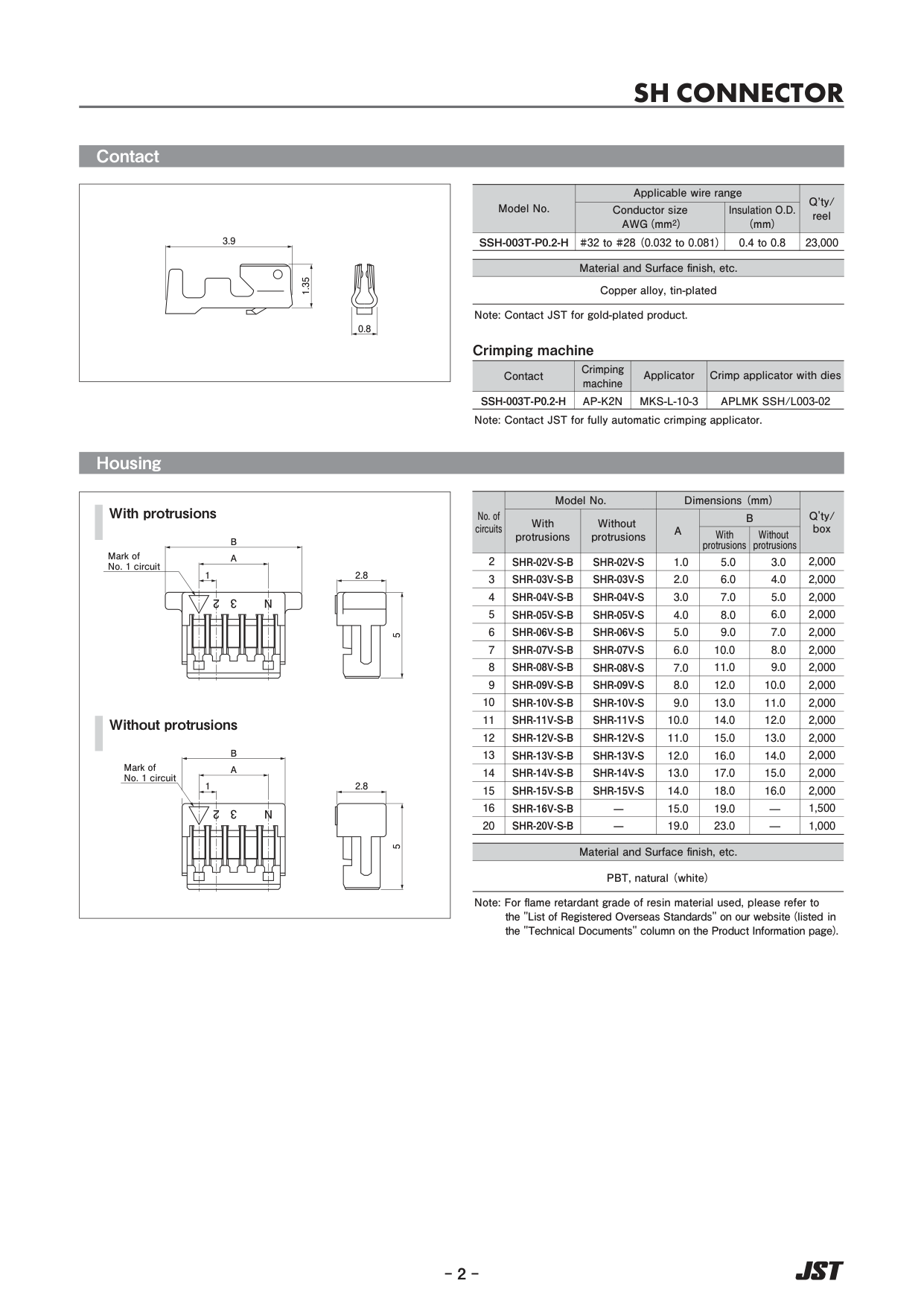
Contact
| Model No. | Conductor size AWG (mm2) | Insulation O.D. (mm) | Q'ty/reel |
|---|---|---|---|
| SSH-003T-P0.2-H | #32 to #28 (0.032 to 0.081) | 0.4 to 0.8 | 23,000 |
Material and finish: copper alloy, tin-plated. Contact dimensions shown: 0.8, 3.9, 1.35. Contact JST for gold-plated product.
| Contact | Crimping machine | Applicator | Crimp applicator with dies |
|---|---|---|---|
| SSH-003T-P0.2-H | AP-K2N | MKS-L-10-3 | APLMK SSH/L003-02 |
Housing (4 circuits)
| No. of circuits | With protrusions | Without protrusions | A | B with protrusions | B without protrusions | Q'ty/box |
|---|---|---|---|---|---|---|
| 4 | SHR-04V-S-B | SHR-04V-S | 3.0 | 7.0 | 5.0 | 2,000 |
The housing table covers 2-16 and 20 circuits. Housing material: PBT, natural (white). The housing drawing shows 2.8 and 5 and marks the No. 1 circuit.
Page 3 — Header
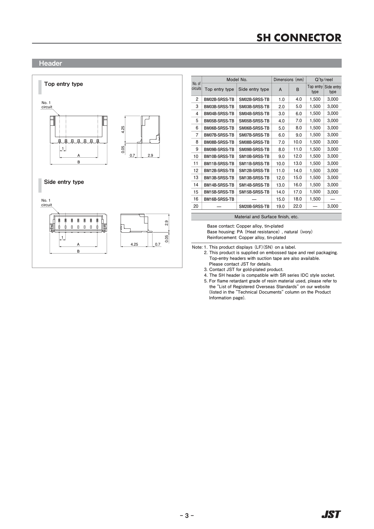
| No. of circuits | Top entry type | Side entry type | A | B | Q'ty/reel top entry | Q'ty/reel side entry |
|---|---|---|---|---|---|---|
| 2 | BM02B-SRSS-TB | SM02B-SRSS-TB | 1.0 | 4.0 | 1,500 | 3,000 |
| 3 | BM03B-SRSS-TB | SM03B-SRSS-TB | 2.0 | 5.0 | 1,500 | 3,000 |
| 4 | BM04B-SRSS-TB | SM04B-SRSS-TB | 3.0 | 6.0 | 1,500 | 3,000 |
| 5 | BM05B-SRSS-TB | SM05B-SRSS-TB | 4.0 | 7.0 | 1,500 | 3,000 |
| 6 | BM06B-SRSS-TB | SM06B-SRSS-TB | 5.0 | 8.0 | 1,500 | 3,000 |
| 7 | BM07B-SRSS-TB | SM07B-SRSS-TB | 6.0 | 9.0 | 1,500 | 3,000 |
| 8 | BM08B-SRSS-TB | SM08B-SRSS-TB | 7.0 | 10.0 | 1,500 | 3,000 |
| 9 | BM09B-SRSS-TB | SM09B-SRSS-TB | 8.0 | 11.0 | 1,500 | 3,000 |
| 10 | BM10B-SRSS-TB | SM10B-SRSS-TB | 9.0 | 12.0 | 1,500 | 3,000 |
| 11 | BM11B-SRSS-TB | SM11B-SRSS-TB | 10.0 | 13.0 | 1,500 | 3,000 |
| 12 | BM12B-SRSS-TB | SM12B-SRSS-TB | 11.0 | 14.0 | 1,500 | 3,000 |
| 13 | BM13B-SRSS-TB | SM13B-SRSS-TB | 12.0 | 15.0 | 1,500 | 3,000 |
| 14 | BM14B-SRSS-TB | SM14B-SRSS-TB | 13.0 | 16.0 | 1,500 | 3,000 |
| 15 | BM15B-SRSS-TB | SM15B-SRSS-TB | 14.0 | 17.0 | 1,500 | 3,000 |
| 16 | BM16B-SRSS-TB | — | 15.0 | 18.0 | 1,500 | — |
| 20 | — | SM20B-SRSS-TB | 19.0 | 22.0 | — | 3,000 |
Top-entry header drawing: A = circuit 1 to last circuit, 1 = pitch, B = overall width, height 4.25 above a 0.05 standoff, depth 2.9 plus 0.7 contact tail. Side-entry header drawing: height 2.9 with 0.05 standoff, depth 4.25 plus 0.7.
Material and surface finish: base contact copper alloy, tin-plated; base housing PA (heat resistance), natural (ivory); reinforcement copper alloy, tin-plated.
Notes: 1. This product displays (LF)(SN) on a label. 2. This product is supplied on embossed tape and reel packaging; top-entry headers with suction tape are also available (contact JST). 3. Contact JST for gold-plated product. 4. The SH header is compatible with SR series IDC style socket. 5. For the flame retardant grade of the resin material, see the "List of Registered Overseas Standards" on the JST website.
Page 4 — Model number allocation
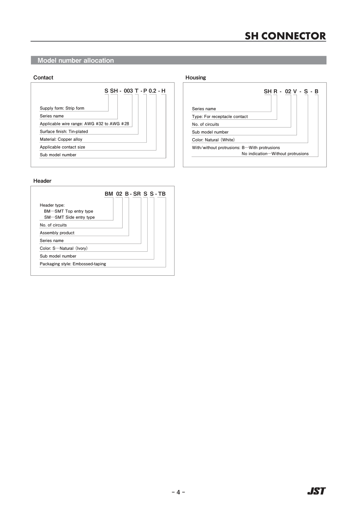
- Contact: SSH-003T-P0.2-H. S = supply form (strip form); SH = series name; 003 = applicable wire range AWG #32 to AWG #28; T = surface finish tin-plated; P = material copper alloy; 0.2 = applicable contact size; H = sub model number.
- Housing: SHR-02V-S-B. SH series; R = receptacle; 02 = number of circuits; V = sub model; S = natural (white); B = with protrusions (no indication = without protrusions).
- Header: BM02B-SRSS-TB. BM = SMT top entry type (SM = SMT side entry type); 02 = number of circuits; B = assembly product; SR = series name; S = natural (ivory); S = sub model number; TB = embossed taping.
Figures and diagrams from the PDF
Preview the extracted datasheet assets and open any image in a separate tab for closer inspection.
Use this datasheet from any agent
Send the page, markdown, chunks, or search endpoint to ChatGPT, Claude, embedr-app, or your own tooling.