
MCP73831T-2ACI/OT Li-Ion/LiPo Charger IC
Microchip MCP73831T-2ACI/OT miniature single-cell Li-Ion/Li-Polymer linear charge-management controller in SOT-23-5. This is the charger IC only; USB-C connectors, CC resistors, passives, battery connector, and protection circuitry are separate components or reference-design elements.
Miniature Single-Cell, Fully Integrated Li-Ion, Li-Polymer Charge Management Controllers
Features
• Linear Charge Management Controller:
- Integrated Pass Transistor
- Integrated Current Sense
- Reverse Discharge Protection
• High-Accuracy Preset Voltage Regulation: ± 0.75%
- Four Voltage Regulation Options:
- 4.20V, 4.35V, 4.40V, 4.50V
- Programmable Charge Current: 15 mA to 500 mA
- Selectable Preconditioning: - 10%, 20%, 40%, or Disable
- Selectable End-of-Charge Control: - 5%, 7.5%, 10%, or 20%
- Charge Status Output
- Tri-State Output - MCP73831
- Open-Drain Output - MCP73832
• Automatic Power-Down
- Thermal Regulation
• Temperature Range: $-40^{\circ}C$ to $+85^{\circ}C$
- Packaging:
- 8-Lead, 2 mm x 3 mm DFN
- 5-Lead, SOT-23
Applications
• Lithium-Ion/Lithium-Polymer Battery Chargers
• Personal Data Assistants
- Cellular Telephones
- Digital Cameras
- MP3 Players
- Bluetooth Headsets
- USB Chargers
Typical Application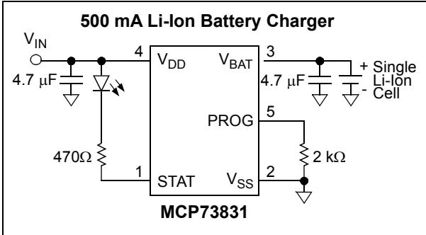
Description
The MCP73831/2 devices are highly advanced linear charge management controllers for use in space-limited, cost-sensitive applications. The MCP73831/2 are available in an 8-Lead, 2 mm x 3 mm DFN package or a 5-Lead, SOT-23 package. Along with their small physical size, the low number of external components required make the MCP73831/2 ideally suited for portable applications. For applications charging from a USB port, the MCP73831/2 adhere to all the specifications governing the USB power bus.
The MCP73831/2 employ a constant-current/constant-voltage charge algorithm with selectable preconditioning and charge termination. The constant voltage regulation is fixed with four available options: 4.20V, 4.35V, 4.40V or 4.50V, to accommodate new, emerging battery charging requirements. The constant current value is set with one external resistor. The MCP73831/2 devices limit the charge current based on die temperature during high power or high ambient conditions. This thermal regulation optimizes the charge cycle time while maintaining device reliability.
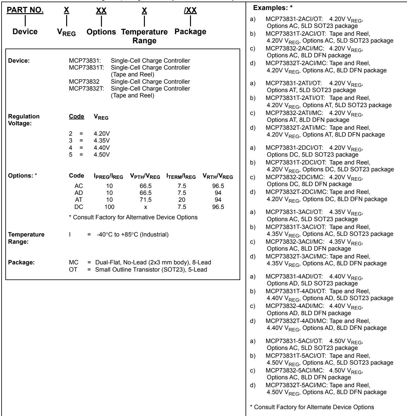
Several options are available for the preconditioning threshold, preconditioning current value, charge termination value and automatic recharge threshold. The preconditioning value and charge termination value are set as a ratio or percentage of the programmed constant current value. Preconditioning can be disabled. Refer to Section 1.0 “Electrical Characteristics” for available options and the Product Identification System for standard options.
The MCP73831/2 devices are fully specified over the ambient temperature range of $-40^{\circ}C$ to $+85^{\circ}C$ .
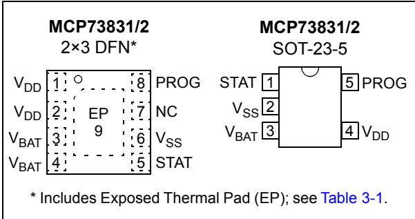
Package Types
| MCP73831/2 2×3 DFN* | ||
| V_DD | 1: ○ | PROG |
| V_DD | 2: EP | NC |
| VBAT | 3: 9 | VSS |
| VBAT | 4: - | STAT |
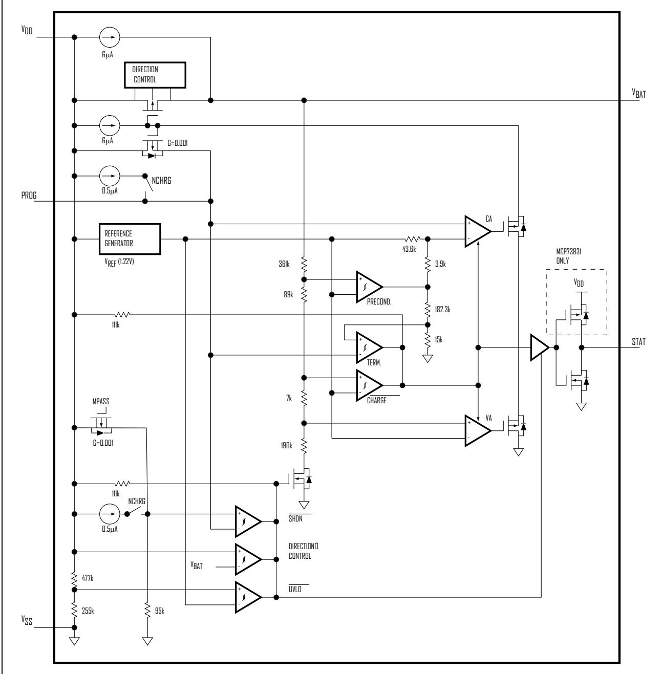
Functional Block Diagram
1.0 ELECTRICAL CHARACTERISTICS
Absolute Maximum Ratings†
$V_{DD}$ .....7.0V
All Inputs and Outputs w.r.t. $V_{SS}$ .....-0.3 to ( $V_{DD}+0.3$ )V
Maximum Junction Temperature, $T_{J}$ .....Internally Limited
Storage temperature .....-65°C to +150°C
ESD protection on all pins:
Human Body Model (1.5 kΩ in Series with 100 pF).....≥4 kV
Machine Model (200 pF, No Series Resistance).....400V † Notice: Stresses above those listed under “Maximum Ratings” may cause permanent damage to the device. This is a stress rating only and functional operation of the device at those or any other conditions above those indicated in the operational listings of this specification is not implied. Exposure to maximum rating conditions for extended periods may affect device reliability.
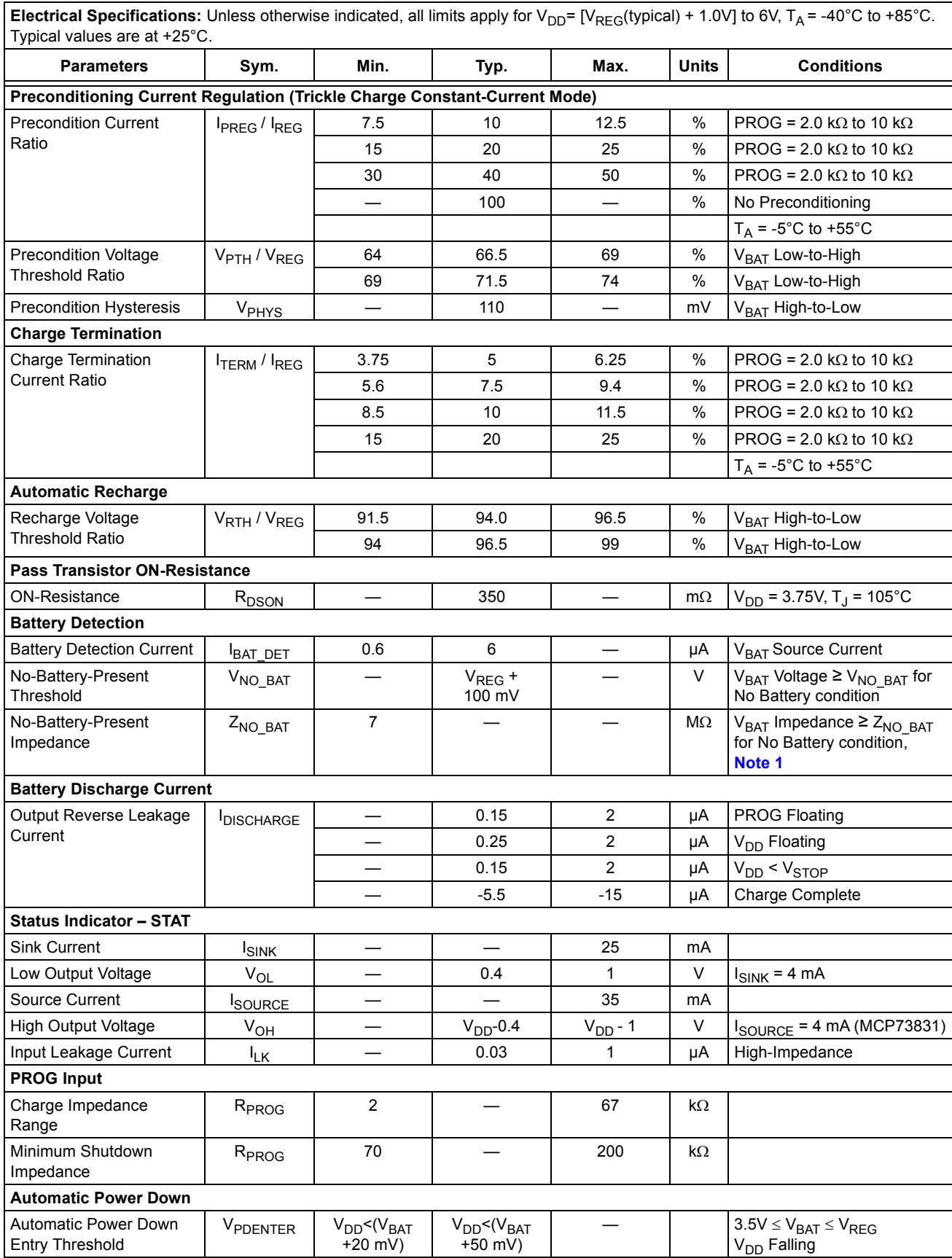
DC CHARACTERISTICS
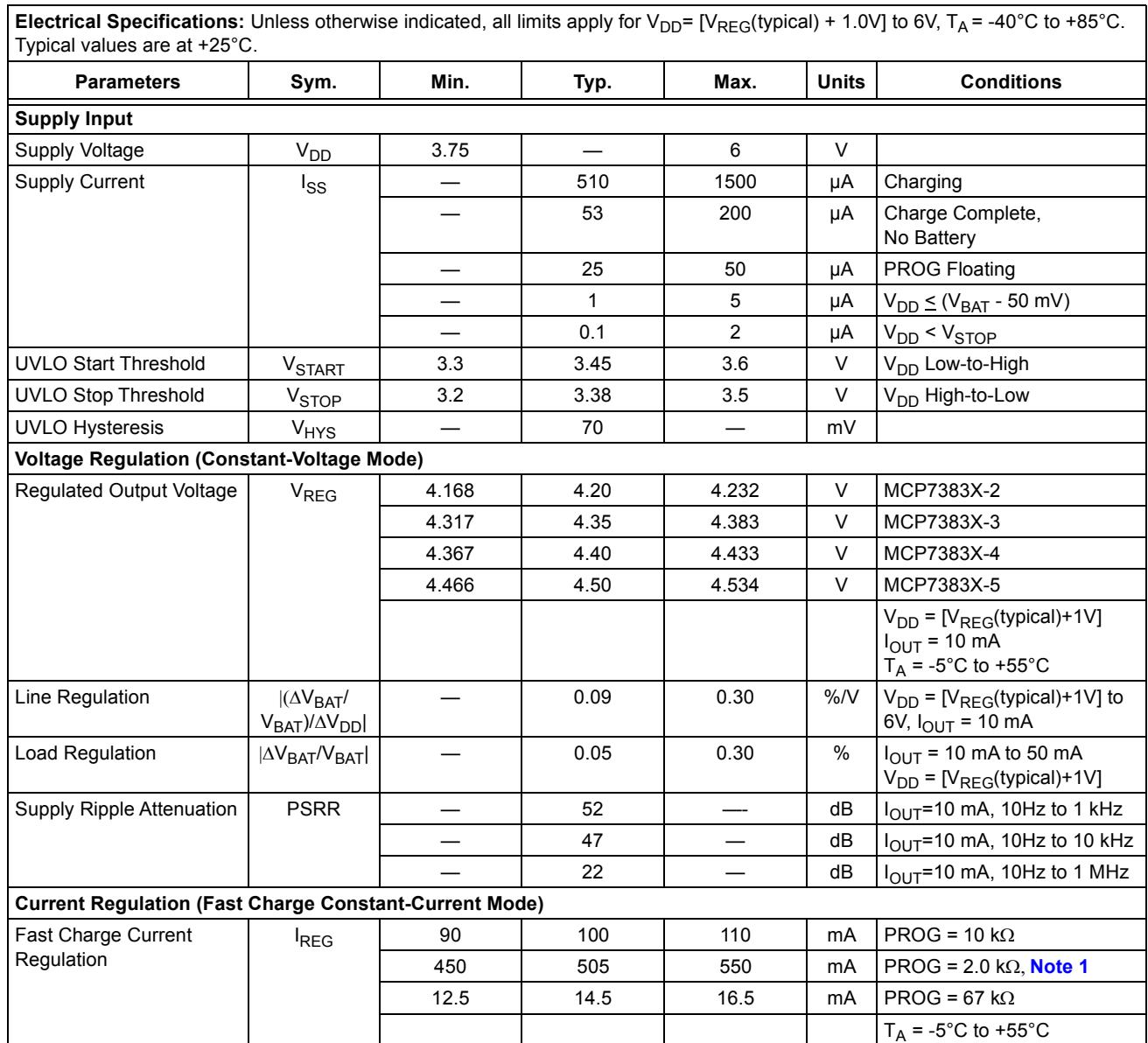
| Electrical Specifications: Unless otherwise indicated, all limits apply for $V_{DD}=[V_{REG}(typical)+1.0V]$ to 6V, $T_A=-40°C$ to +85°C. Typical values are at +25°C. | ||||||
| Parameters | Sym. | Min. | Typ. | Max. | Units | Conditions |
| Supply Input | ||||||
| Supply Voltage | $V_{DD}$ | 3.75 | — | 6 | V | |
| Supply Current | $I_{SS}$ | — | 510 | 1500 | μA | Charging |
| — | 53 | 200 | μA | Charge Complete, No Battery | ||
| — | 25 | 50 | μA | PROG Floating | ||
| — | 1 | 5 | μA | $V_{DD}\leq(V_{BAT}-50mV)$ | ||
| — | 0.1 | 2 | μA | $V_{DD}<V_{STOP}$ | ||
| UVLO Start Threshold | $V_{START}$ | 3.3 | 3.45 | 3.6 | V | $V_{DD}$ Low-to-High |
| UVLO Stop Threshold | $V_{STOP}$ | 3.2 | 3.38 | 3.5 | V | $V_{DD}$ High-to-Low |
| UVLO Hysteresis | $V_{HYS}$ | — | 70 | — | mV | |
| Voltage Regulation (Constant-Voltage Mode) | ||||||
| Regulated Output Voltage | $V_{REG}$ | 4.168 | 4.20 | 4.232 | V | MCP7383X-2 |
| 4.317 | 4.35 | 4.383 | V | MCP7383X-3 | ||
| 4.367 | 4.40 | 4.433 | V | MCP7383X-4 | ||
| 4.466 | 4.50 | 4.534 | V | MCP7383X-5 | ||
| $V_{DD}=[V_{REG}(typical)+1V]$ $I_{OUT}=10mA$ $T_A=-5°C to +55°C$ | ||||||
| Line Regulation | $\left|\left(\Delta V_{BAT}/V_{BAT}\right)/\Delta V_{DD}\right|$ | — | 0.09 | 0.30 | %/V | $V_{DD}=[V_{REG}(typical)+1V]$ to 6V, $I_{OUT}=10mA$ |
| Load Regulation | $\left|\Delta V_{BAT}/V_{BAT}\right|$ | — | 0.05 | 0.30 | % | $I_{OUT}=10mA to 50mA$ $V_{DD}=[V_{REG}(typical)+1V]$ |
| Supply Ripple Attenuation | PSRR | — | 52 | — | dB | $I_{OUT}=10mA, 10Hz to 1kHz$ |
| — | 47 | — | dB | $I_{OUT}=10mA, 10Hz to 1kHz$ | ||
| — | 22 | — | dB | $I_{OUT}=10mA, 10Hz to 1MHz$ | ||
| Current Regulation (Fast Charge Constant-Current Mode) | ||||||
| Fast Charge Current Regulation | $I_{REG}$ | 90 | 100 | 110 | mA | PROG = 10 kΩ |
| 450 | 505 | 550 | mA | PROG = 2.0 kΩ, Note 1 | ||
| 12.5 | 14.5 | 16.5 | mA | PROG = 67 kΩ | ||
| $T_A=-5°C to +55°C$ | ||||||
| Preconditioning Current Regulation (Trickle Charge Constant-Current Mode) | ||||||
| Precondition Current Ratio | $I_{PREG}/I_{REG}$ | 7.5 | 10 | 12.5 | % | PROG = 2.0 kΩ to 10 kΩ |
| 15 | 20 | 25 | % | PROG = 2.0 kΩ to 10 kΩ | ||
| 30 | 40 | 50 | % | PROG = 2.0 kΩ to 10 kΩ | ||
| — | 100 | — | % | No Preconditioning | ||
| $T_A$ = -5°C to +55°C | ||||||
| Precondition Voltage Threshold Ratio | $V_{PTH}/V_{REG}$ | 64 | 66.5 | 69 | % | $V_{BAT}$ Low-to-High |
| 69 | 71.5 | 74 | % | $V_{BAT}$ Low-to-High | ||
| Precondition Hysteresis | $V_{PHYS}$ | — | 110 | — | mV | $V_{BAT}$ High-to-Low |
| Charge Termination | ||||||
| Charge Termination Current Ratio | $I_{TERM}/I_{REG}$ | 3.75 | 5 | 6.25 | % | PROG = 2.0 kΩ to 10 kΩ |
| 5.6 | 7.5 | 9.4 | % | PROG = 2.0 kΩ to 10 kΩ | ||
| 8.5 | 10 | 11.5 | % | PROG = 2.0 kΩ to 10 kΩ | ||
| 15 | 20 | 25 | % | PROG = 2.0 kΩ to 10 kΩ | ||
| $T_A$ = -5°C to +55°C | ||||||
| Automatic Recharge | ||||||
| Recharge Voltage Threshold Ratio | $V_{RTH}/V_{REG}$ | 91.5 | 94.0 | 96.5 | % | $V_{BAT}$ High-to-Low |
| 94 | 96.5 | 99 | % | $V_{BAT}$ High-to-Low | ||
| Pass Transistor ON-Resistance | ||||||
| ON-Resistance | $R_{DSON}$ | — | 350 | — | mΩ | $V_{DD}$ = 3.75V, $T_J$ = 105°C |
| Battery Detection | ||||||
| Battery Detection Current | $I_{BAT\_DET}$ | 0.6 | 6 | — | μA | $V_{BAT}$ Source Current |
| No-Battery-Present Threshold | $V_{NO\_BAT}$ | — | $V_{REG}$ +100 mV | — | V | $V_{BAT}$ Voltage ≥ $V_{NO\_BAT}$ for No Battery condition |
| No-Battery-Present Impedance | $Z_{NO\_BAT}$ | 7 | — | — | MΩ | $V_{BAT}$ Impedance ≥ $Z_{NO\_BAT}$ for No Battery condition, Note 1 |
| Battery Discharge Current | ||||||
| Output Reverse Leakage Current | $I_{DISCHARGE}$ | — | 0.15 | 2 | μA | PROG Floating |
| — | 0.25 | 2 | μA | $V_{DD}$ Floating | ||
| — | 0.15 | 2 | μA | $V_{DD}< V_{STOP}$ | ||
| — | -5.5 | -15 | μA | Charge Complete | ||
| Status Indicator - STAT | ||||||
| Sink Current | $I_{SINK}$ | — | — | 25 | mA | |
| Low Output Voltage | $V_{OL}$ | — | 0.4 | 1 | V | $I_{SINK}$ = 4 mA |
| Source Current | $I_{SOURCE}$ | — | — | 35 | mA | |
| High Output Voltage | $V_{OH}$ | — | $V_{DD}$ -0.4 | $V_{DD}$ -1 | V | $I_{SOURCE}$ = 4 mA (MCP73831) |
| Input Leakage Current | $I_{LK}$ | — | 0.03 | 1 | μA | High-Impedance |
| PROG Input | ||||||
| Charge Impedance Range | $R_{PROG}$ | 2 | — | 67 | kΩ | |
| Minimum Shutdown Impedance | $R_{PROG}$ | 70 | — | 200 | kΩ | |
| Automatic Power Down | ||||||
| Automatic Power Down Entry Threshold | $V_{PDENTER}$ | $V_{DD}<(V_{BAT}+20 mV)$ | $V_{DD}<(V_{BAT}+50 mV)$ | — | 3.5V ≤ $V_{BAT}$ ≤ $V_{REG}$ $V_{DD}$ Falling | |
Note 1: Not production tested. Ensured by design.
Note 1: Not production tested. Ensured by design.
DC CHARACTERISTICS (CONTINUED)
| Electrical Specifications: Unless otherwise indicated, all limits apply for $V_{DD} = [V_{REG}(typical) + 1.0V]$ to 6V, $T_A = -40°C$ to +85°C. Typical values are at +25°C. | ||||||
| Parameters | Sym. | Min. | Typ. | Max. | Units | Conditions |
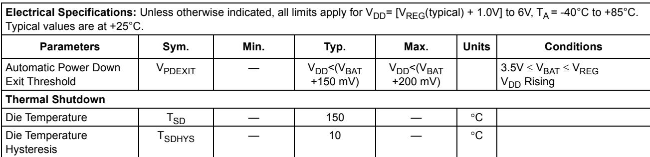
| Automatic Power Down Exit Threshold | $V_{PDEXIT}$ | — | $V_{DD} < (V_{BAT} + 150\ mV)$ | $V_{DD} < (V_{BAT} + 200\ mV)$ | 3.5V ≤ $V_{BAT}$ ≤ $V_{REG}$ $V_{DD}$ Rising | |
| Thermal Shutdown | ||||||
| Die Temperature | $T_{SD}$ | — | 150 | — | °C | |
| Die Temperature Hysteresis | $T_{SDHYS}$ | — | 10 | — | °C | |
Note 1: Not production tested. Ensured by design.
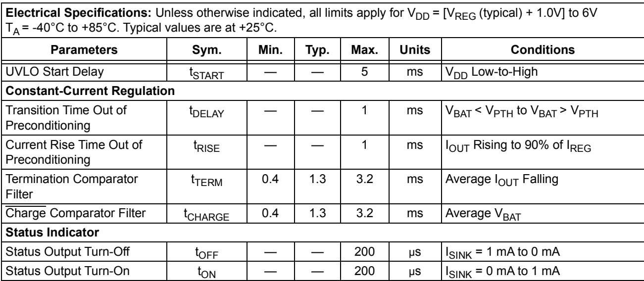
AC CHARACTERISTICS
| Electrical Specifications: Unless otherwise indicated, all limits apply for $V_{DD} = [V_{REG} (typical) + 1.0V]$ to 6V $T_A = -40°C$ to +85°C. Typical values are at +25°C. | ||||||
| Parameters | Sym. | Min. | Typ. | Max. | Units | Conditions |
| UVLO Start Delay | $t_{START}$ | — | — | 5 | ms | $V_{DD}$ Low-to-High |
| Constant-Current Regulation | ||||||
| Transition Time Out of Preconditioning | $t_{DELAY}$ | — | — | 1 | ms | $V_{BAT} < V_{PTH}$ to $V_{BAT} > V_{PTH}$ |
| Current Rise Time Out of Preconditioning | $t_{RISE}$ | — | — | 1 | ms | $I_{OUT}$ Rising to 90% of $I_{REG}$ |
| Termination Comparator Filter | $t_{TERM}$ | 0.4 | 1.3 | 3.2 | ms | Average $I_{OUT}$ Falling |
| $\overline{Charge}$ Comparator Filter | $t_{CHARGE}$ | 0.4 | 1.3 | 3.2 | ms | Average $V_{BAT}$ |
| Status Indicator | ||||||
| Status Output Turn-Off | $t_{OFF}$ | — | — | 200 | μs | $I_{SINK} = 1 mA$ to 0 mA |
| Status Output Turn-On | $t_{ON}$ | — | — | 200 | μs | $I_{SINK} = 0 mA$ to 1 mA |
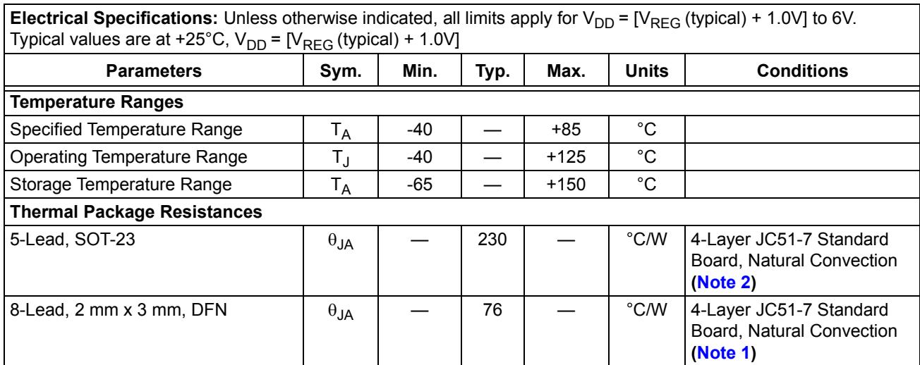
TEMPERATURE SPECIFICATIONS
| Electrical Specifications: Unless otherwise indicated, all limits apply for $V_{DD} = [V_{REG} (typical) + 1.0V]$ to 6V.Typical values are at +25°C, $V_{DD} = [V_{REG} (typical) + 1.0V]$ | ||||||
| Parameters | Sym. | Min. | Typ. | Max. | Units | Conditions |
| Temperature Ranges | ||||||
| Specified Temperature Range | $T_A$ | -40 | — | +85 | °C | |
| Operating Temperature Range | $T_J$ | -40 | — | +125 | °C | |
| Storage Temperature Range | $T_A$ | -65 | — | +150 | °C | |
| Thermal Package Resistances | ||||||
| 5-Lead, SOT-23 | $θ_{JA}$ | — | 230 | — | °C/W | 4-Layer JC51-7 Standard Board, Natural Convection (Note 2) |
| 8-Lead, 2 mm x 3 mm, DFN | $θ_{JA}$ | — | 76 | — | °C/W | 4-Layer JC51-7 Standard Board, Natural Convection (Note 1) |
2: With large copper area on the PCB, the SOT-23-5 thermal resistance ( $\theta_{JA}$ ) can reach a typical value of 130°C/W or better.
Note 1: This represents the minimum copper condition on the PCB (Printed Circuit Board).
NOTES:
2.0 TYPICAL PERFORMANCE CURVES
Note: The graphs and tables provided following this note are a statistical summary based on a limited number of samples and are provided for informational purposes only. The performance characteristics listed herein are not tested or guaranteed. In some graphs or tables, the data presented may be outside the specified operating range (e.g., outside specified power supply range) and therefore outside the warranted range.
Note: Unless otherwise indicated, $V_{DD} = [V_{REG}(typical) + 1V]$ , $I_{OUT} = 10 mA and T_{A} = +25^{\circ}C$ , Constant-Voltage mode.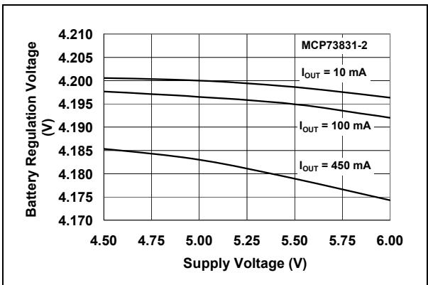
FIGURE 2-1: Battery Regulation Voltage ( $V_{BAT}$ ) vs. Supply Voltage ( $V_{DD}$ ).
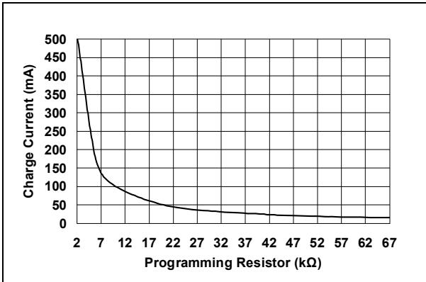
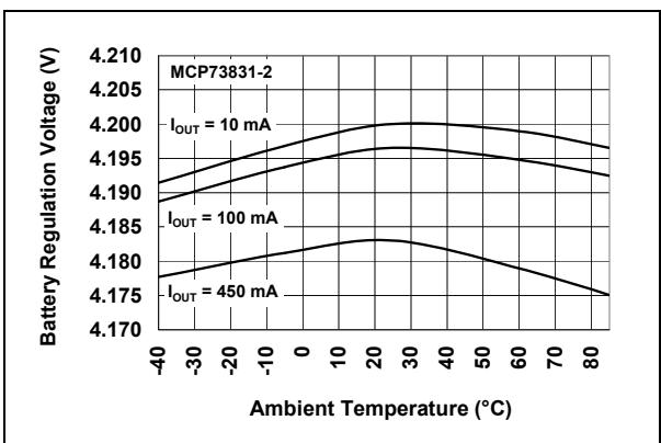
FIGURE 2-4: Charge Current ( $I_{OUT}$ ) vs. Programming Resistor ( $R_{PROG}$ ).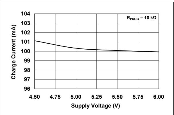
FIGURE 2-2: Battery Regulation Voltage ( $V_{BAT}$ ) vs. Ambient Temperature ( $T_{A}$ ).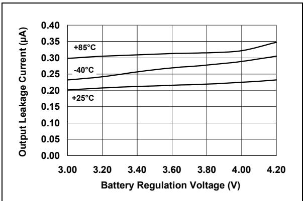
FIGURE 2-3: Output Leakage Current ( $I_{DISCHARGE}$ ) vs. Battery Regulation Voltage ( $V_{BAT}$ ).
FIGURE 2-5: Charge Current ( $I_{OUT}$ ) vs. Supply Voltage ( $V_{DD}$ ).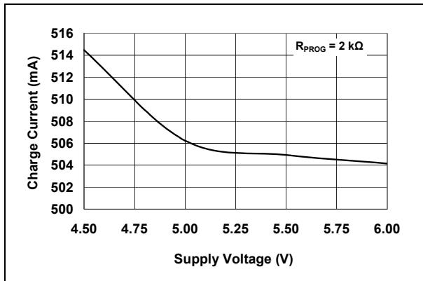
FIGURE 2-6: Charge Current ( $I_{OUT}$ ) vs. Supply Voltage ( $V_{DD}$ ).
TYPICAL PERFORMANCE CURVES (CONTINUED)
Note: Unless otherwise indicated, $V_{DD} = [V_{REG}(typical) + 1V]$ , $I_{OUT} = 10 mA and T_{A} = +25^{\circ}C$ , Constant-Voltage mode.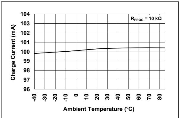
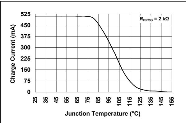
FIGURE 2-7: Charge Current ( $I_{OUT}$ ) vs. Ambient Temperature ( $T_{A}$ ).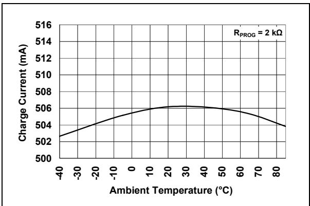
FIGURE 2-10: Charge Current ( $I_{OUT}$ ) vs. Junction Temperature ( $T_{J}$ ).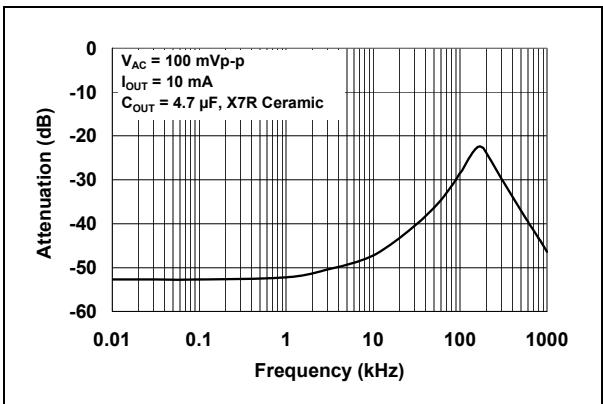
FIGURE 2-8: Charge Current ( $I_{OUT}$ ) vs. Ambient Temperature ( $T_{A}$ ).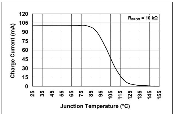
FIGURE 2-9: Charge Current ( $I_{OUT}$ ) vs. Junction Temperature ( $T_{J}$ ).
FIGURE 2-11: Power Supply Ripple Rejection (PSRR).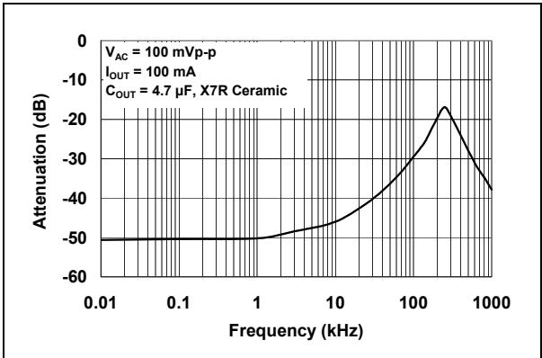
FIGURE 2-12: Power Supply Ripple Rejection (PSRR).
TYPICAL PERFORMANCE CURVES (CONTINUED)
Note: Unless otherwise indicated, $V_{DD} = [V_{REG}(typical) + 1V]$ , $I_{OUT} = 10 mA$ and $T_{A} = +25^{\circ}C$ , Constant-Voltage mode.
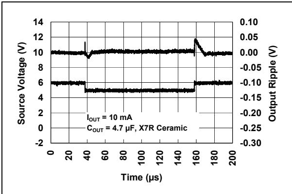
FIGURE 2-13: Line Transient Response.
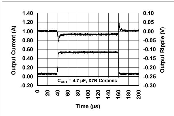
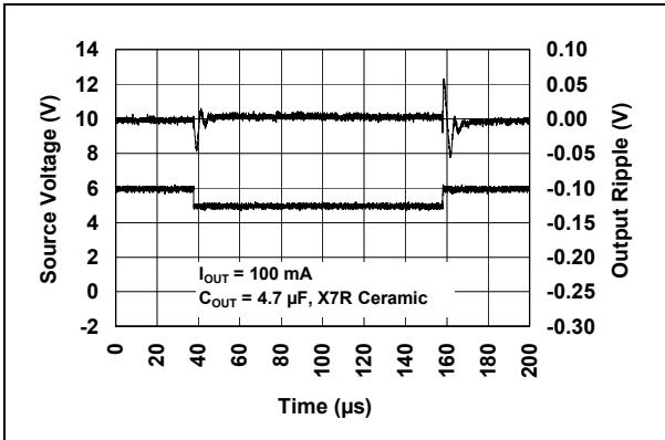
FIGURE 2-14: Line Transient Response.
FIGURE 2-16: Load Transient Response.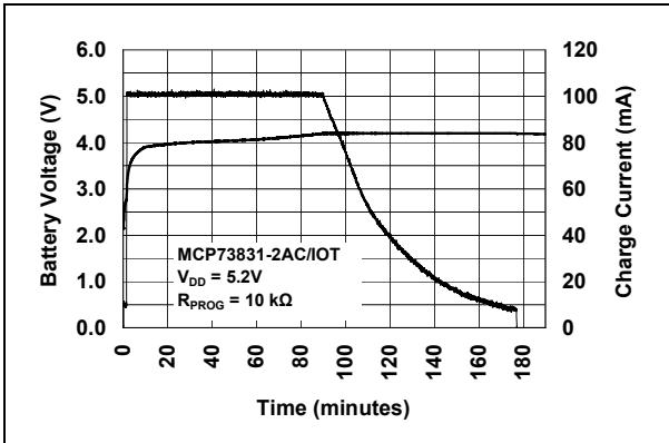
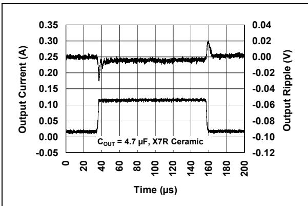
FIGURE 2-15: Load Transient Response.
FIGURE 2-17: Complete Charge Cycle (180 mAh Li-Ion Battery).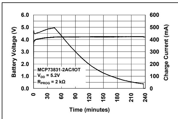
FIGURE 2-18: Complete Charge Cycle (1000 mAh Li-Ion Battery).
NOTES:
3.0 PIN DESCRIPTION
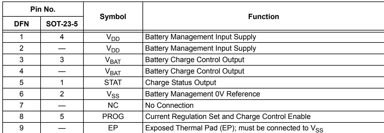
The descriptions of the pins are listed in Table 3-1.
TABLE 3-1: PIN FUNCTION TABLES
| Pin No. | Symbol | Function | |
| DFN | SOT-23-5 | ||
| 1 | 4 | $V_{DD}$ | Battery Management Input Supply |
| 2 | — | $V_{DD}$ | Battery Management Input Supply |
| 3 | 3 | $V_{BAT}$ | Battery Charge Control Output |
| 4 | — | $V_{BAT}$ | Battery Charge Control Output |
| 5 | 1 | STAT | Charge Status Output |
| 6 | 2 | $V_{SS}$ | Battery Management 0V Reference |
| 7 | — | NC | No Connection |
| 8 | 5 | PROG | Current Regulation Set and Charge Control Enable |
| 9 | — | EP | Exposed Thermal Pad (EP); must be connected to $V_{SS}$ |
3.1 Battery Management Input Supply ( $V_{DD}$ )
A supply voltage of $[V_{REG}$ (typical) + 0.3V] to 6V is recommended. Bypass to $V_{SS}$ with a minimum of 4.7 $\mu$ F.
3.2 Battery Charge Control Output ( $V_{BAT}$ )
Connect to positive terminal of battery. Drain terminal of internal P-channel MOSFET pass transistor. Bypass to $V_{SS}$ with a minimum of 4.7 $\mu$ F to ensure loop stability when the battery is disconnected.
3.3 Charge Status Output (STAT)
STAT is an output for connection to an LED for charge status indication. Alternatively, a pull-up resistor can be applied for interfacing to a host microcontroller.
STAT is a tri-state logic output on the MCP73831 and an open-drain output on the MCP73832.
3.4 Battery Management 0V Reference ( $V_{ss}$ )
Connect to negative terminal of battery and input supply.
3.5 Current Regulation Set (PROG)
Preconditioning, fast charge and termination currents are scaled by placing a resistor from PROG to $V_{SS}$ .
The charge management controller can be disabled by allowing the PROG input to float.
3.6 Exposed Thermal Pad (EP)
An internal electrical connection exists between the Exposed Thermal Pad (EP) and the $V_{SS}$ pin. They must be connected to the same potential on the Printed Circuit Board (PCB).
For better thermal performance, it is recommended to add vias from the land area of EP to a copper layer on the other side of the PCB.
NOTES:
4.0 DEVICE OVERVIEW
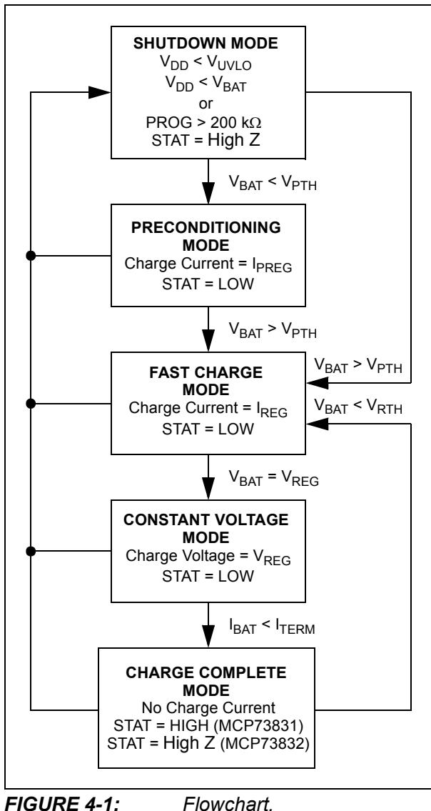
The MCP73831/2 are highly advanced linear charge management controllers. Figure 4-1 depicts the operational flow algorithm from charge initiation to completion and automatic recharge.
4.1 Undervoltage Lockout (UVLO)
An internal UVLO circuit monitors the input voltage and keeps the charger in Shutdown mode until the input supply rises above the UVLO threshold. The UVLO circuitry has a built in hysteresis of 100 mV.
In the event a battery is present when the input power is applied, the input supply must rise to a level 150 mV above the battery voltage before the MCP73831/2 become operational.
The UVLO circuit places the device in Shutdown mode if the input supply falls to within +50 mV of the battery voltage. Again, the input supply must rise to a level 150 mV above the battery voltage before the MCP73831/2 become operational.
The UVLO circuit is always active. Whenever the input supply is below the UVLO threshold or within +50 mV of the voltage at the $V_{BAT}$ pin, the MCP73831/2 are placed in Shutdown mode.
During any UVLO condition, the battery reverse discharge current is less than 2 $\mu$ A.
4.2 Battery Detection
A 6 $\mu$ A (typical) current is sourced by the $V_{BAT}$ pin to determine if a battery is present or not. If the voltage at $V_{BAT}$ rises to $V_{REG} + 100$ mV (typical), the device assumes that a battery is not present. If the voltage stays below $V_{REG} + 100$ mV (typical), the device assumes that a battery is detected. In order to correctly detect a battery insertion, the impedance seen by the $V_{BAT}$ pin before the battery is connected must be greater than 7 M $\Omega$ due to the minimum battery detection current of 0.6 $\mu$ A
4.3 Charge Qualification
For a charge cycle to begin, all UVLO conditions must be met and a battery or output load must be present. A charge current programming resistor must be connected from PROG to $V_{SS}$ . If the PROG pin is open or floating, the MCP73831/2 are disabled and the battery reverse discharge current is less than 2 $\mu$ A. In this manner, the PROG pin acts as a charge enable and can be used as a manual shutdown.
4.4 Preconditioning
If the voltage at the $V_{BAT}$ pin is less than the preconditioning threshold, the MCP73831/2 enter a preconditioning or Trickle Charge mode. The preconditioning threshold is factory set. Refer to Section 1.0 “Electrical Characteristics” for preconditioning threshold options and the Product Identification System for standard options.
In this mode, the MCP73831/2 supply a percentage of the charge current (established with the value of the resistor connected to the PROG pin) to the battery. The percentage or ratio of the current is factory set. Refer to Section 1.0 “Electrical Characteristics” for preconditioning current options and the Product Identification System for standard options.
When the voltage at the $V_{BAT}$ pin rises above the preconditioning threshold, the MCP73831/2 enter the Constant-Current or Fast Charge mode.
4.5 Fast Charge Constant-Current Mode
During the Constant-Current mode, the programmed charge current is supplied to the battery or load. The charge current is established using a single resistor from PROG to $V_{SS}$ . Constant-Current mode is maintained until the voltage at the $V_{BAT}$ pin reaches the regulation voltage, $V_{REG}$ .
4.6 Constant-Voltage Mode
When the voltage at the $V_{BAT}$ pin reaches the regulation voltage, $V_{REG}$ , constant voltage regulation begins. The regulation voltage is factory set to 4.2V, 4.35V, 4.40V or 4.50V with a tolerance of $\pm0.75%$ .
4.7 Charge Termination
The charge cycle is terminated when, during Constant-Voltage mode, the average charge current diminishes below a percentage of the programmed charge current (established with the value of the resistor connected to the PROG pin). A 1 ms filter time on the termination comparator ensures that transient load conditions do not result in premature charge cycle termination. The percentage or ratio of the current is factory set. Refer to Section 1.0 “Electrical Characteristics” for charge termination current options and the Product Identification System for standard options.
The charge current is latched off and the MCP73831/2 enter a Charge Complete mode.
4.8 Automatic Recharge
The MCP73831/2 continuously monitor the voltage at the $V_{BAT}$ pin in the Charge Complete mode. If the voltage drops below the recharge threshold, another charge cycle begins and current is once again supplied to the battery or load. The recharge threshold is factory set. Refer to Section 1.0 “Electrical Characteristics” for recharge threshold options and the Product Identification System for standard options.
4.9 Thermal Regulation
The MCP73831/2 limit the charge current based on the die temperature. The thermal regulation optimizes the charge cycle time while maintaining device reliability. Figure 4-2 depicts the thermal regulation for the MCP73831/2.
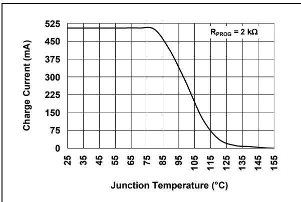
FIGURE 4-2: Thermal Regulation.
4.10 Thermal Shutdown
The MCP73831/2 suspend charge if the die temperature exceeds $150^{\circ}$ C. Charging will resume when the die temperature has cooled by approximately $10^{\circ}$ C.
5.0 DETAILED DESCRIPTION
5.1 Analog Circuitry
5.1.1 BATTERY MANAGEMENT INPUT SUPPLY ( $V_{DD}$ )
The $V_{DD}$ pin is the input supply pin for the MCP73831/2 devices. The MCP73831/2 automatically enter a Power-Down mode if the voltage on the $V_{DD}$ input falls below the UVLO voltage ( $V_{STOP}$ ). This feature prevents draining the battery pack when the $V_{DD}$ supply is not present.
5.1.2 CURRENT REGULATION SET (PROG)
Fast charge current regulation can be scaled by placing a programming resistor ( $R_{PROG}$ ) from the PROG input to $V_{SS}$ . The program resistor and the charge current are calculated using the following equation:
<div class="mineru-algorithm" style="white-space: pre-wrap; font-family:monospace;"> $I_{REG} = \frac{1000V}{R_{PROG}}$Where:
$R_{PROG}$ = kOhms
$I_{REG}$ = milliampere
The preconditioning trickle charge current and the charge termination current are ratiometric to the fast charge current based on the selected device options.
5.1.3 BATTERY CHARGE CONTROL OUTPUT ( $V_{BAT}$ )
The battery charge control output is the drain terminal of an internal P-channel MOSFET. The MCP73831/2 provide constant current and voltage regulation to the battery pack by controlling this MOSFET in the linear region. The battery charge control output should be connected to the positive terminal of the battery pack.
5.2 Digital Circuitry
5.2.1 STATUS INDICATOR (STAT)
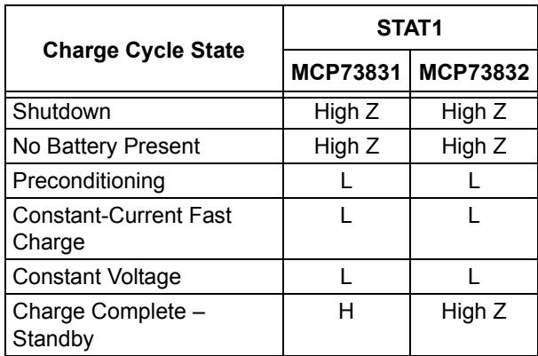
The charge status output of the MCP73831 has three different states: High (H), Low (L), and High-Impedance (High Z). The charge status output of the MCP73832 is open-drain. It has two different states: Low (L) and High-Impedance (High Z). The charge status output can be used to illuminate one, two or tri-color LEDs. Optionally, the charge status output can be used as an interface to a host microcontroller.
Table 5-1 summarizes the state of the status output during a charge cycle.
TABLE 5-1: STATUS OUTPUT
| Charge Cycle State | STAT1 | |
| MCP73831 | MCP73832 | |
| Shutdown | High Z | High Z |
| No Battery Present | High Z | High Z |
| Preconditioning | L | L |
| Constant-Current Fast Charge | L | L |
| Constant Voltage | L | L |
| Charge Complete – Standby | H | High Z |
5.2.2 DEVICE DISABLE (PROG)
The current regulation set input pin (PROG) can be used to terminate a charge at any time during the charge cycle, as well as to initiate a charge cycle or initiate a recharge cycle.
Placing a programming resistor from the PROG input to $V_{SS}$ enables the device. Allowing the PROG input to float or by applying a logic-high input signal, disables the device and terminates a charge cycle. When disabled, the device's supply current is reduced to 25 $\mu$ A, typically.
NOTES:
6.0 APPLICATIONS
The MCP73831/2 are designed to operate in conjunction with a host microcontroller or in a standalone application. The MCP73831/2 provide the preferred charge algorithm for Lithium-Ion and Lithium-Polymer cells. The algorithm uses a constant current followed by a constant voltage charging method. Figure 6-1 depicts a typical stand-alone application circuit, while Figure 6-2 and Figure 6-3 depict the accompanying charge profile.
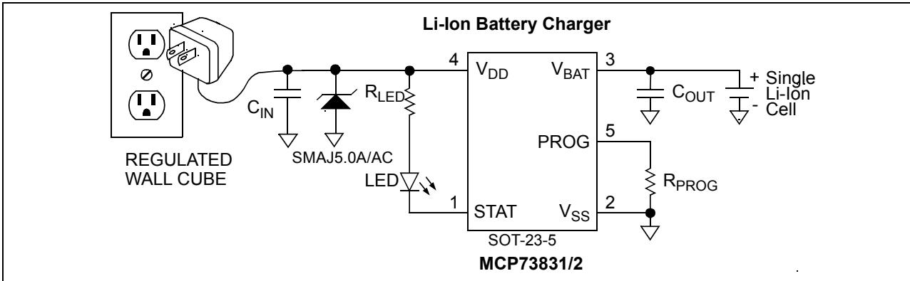
FIGURE 6-1: Typical Application Circuit.
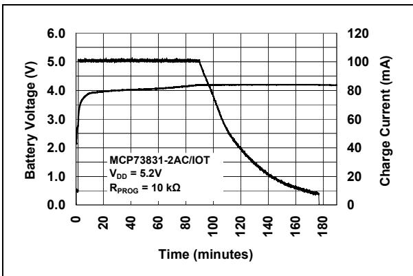
FIGURE 6-2: Typical Charge Profile (180 mAh Battery).
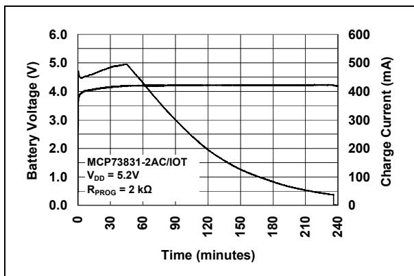
FIGURE 6-3: Typical Charge Profile in Thermal Regulation (1000 mAh Battery).
6.1 Application Circuit Design
Due to the low efficiency of linear charging, the most important factors are thermal design and cost, which are a direct function of the input voltage, output current and thermal impedance between the battery charger and the ambient cooling air. The worst-case situation is when the device has transitioned from the Preconditioning mode to the Constant-Current mode. In this situation, the battery charger has to dissipate the maximum power. A trade-off must be made between the charge current, cost and thermal requirements of the charger.
6.1.1 COMPONENT SELECTION
Selection of the external components in Figure 6-1 is crucial to the integrity and reliability of the charging system. The following discussion is intended as a guide for the component selection process.
6.1.1.1 Current Programming Resistor ( $R_{PROG}$ )
The preferred fast charge current for Lithium-Ion cells is at the 1C rate, with an absolute maximum current at the 2C rate. For example, a 500 mAh battery pack has a preferred fast charge current of 500 mA. Charging at this rate provides the shortest charge cycle times without degradation to the battery pack performance or life.
6.1.1.2 Input Overvoltage Protection (IOVP)
Input overvoltage protection must be used when the input power source is hot-pluggable. This includes USB cables and Wall-type power supplies. The cabling of these supplies acts as an inductor. When the supplies are connected/disconnected from the system, large voltage transients are created which may damage the system circuitry. These transients should be snubbed out. A transzorb connected from the V+ input supply connector to the 0V ground reference will snub the transients.
6.1.1.3 Thermal Considerations
The worst-case power dissipation in the battery charger occurs when the input voltage is at the maximum and the device has transitioned from the Preconditioning mode to the Constant-Current mode. In this case, the power dissipation is:
<div class="mineru-algorithm" style="white-space: pre-wrap; font-family:monospace;"> PowerDissipation = $(V_{DDMAX} - V_{PTHMIN}) \times I_{REGMAX}$ Where: $V_{DDMAX}$ = the maximum input voltage $I_{REGMAX}$ = the maximum fast charge current $V_{PTHMIN}$ = the minimum transition threshold voltage </div>Power dissipation with a 5V, ±10% input voltage source
<div class="mineru-algorithm" style="white-space: pre-wrap; font-family:monospace;"> PowerDissipation = $(5.5V - 2.7V) \times 550mA = 1.54W$ </div>This power dissipation with the battery charger in the SOT-23-5 package will cause thermal regulation to be entered as depicted in Figure 6-3. Alternatively, the 2mm x 3mm DFN package could be utilized to reduce charge cycle times.
6.1.1.4 External Capacitors
The MCP73831/2 are stable with or without a battery load. In order to maintain good AC stability in the Constant-Voltage mode, a minimum capacitance of 4.7 $\mu$ F is recommended to bypass the $V_{BAT}$ pin to $V_{SS}$ . This capacitance provides compensation when there is no battery load. In addition, the battery and interconnections appear inductive at high frequencies. These elements are in the control feedback loop during Constant-Voltage mode. Therefore, the bypass capacitance may be necessary to compensate for the inductive nature of the battery pack.
Virtually any good quality output filter capacitor can be used, independent of the capacitor's minimum Effective Series Resistance (ESR) value. The actual value of the capacitor (and its associated ESR) depends on the output load current. A 4.7 $\mu$ F ceramic, tantalum or aluminum electrolytic capacitor at the output is usually sufficient to ensure stability for output currents up to a 500 mA.
6.1.1.5 Reverse-Blocking Protection
The MCP73831/2 provide protection from a faulted or shorted input. Without the protection, a faulted or shorted input would discharge the battery pack through the body diode of the internal pass transistor.
6.1.1.6 Charge Inhibit
The current regulation set input pin (PROG) can be used to terminate a charge at any time during the charge cycle, as well as to initiate a charge cycle or initiate a recharge cycle.
Placing a programming resistor from the PROG input to $V_{SS}$ enables the device. Allowing the PROG input to float or by applying a logic-high input signal, disables the device and terminates a charge cycle. When disabled, the device's supply current is reduced to 25 $\mu$ A, typically.
6.1.1.7 Charge Status Interface
A status output provides information on the state of charge. The output can be used to illuminate external LEDs or interface to a host microcontroller. Refer to Table 5-1 for a summary of the state of the status output during a charge cycle.
6.2 PCB Layout Issues
For optimum voltage regulation, place the battery pack as close as possible to the device's $V_{BAT}$ and $V_{SS}$ pins. This is recommended to minimize voltage drops along the high current-carrying PCB traces.
If the PCB layout is used as a heat sink, adding many vias in the heat sink pad can help conduct more heat to the PCB backplane, thus reducing the maximum junction temperature. Figure 6-4 and Figure 6-5 depict a typical layout with PCB heatsinking.
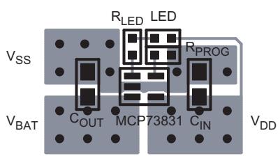
FIGURE 6-4: Typical Layout (Top).
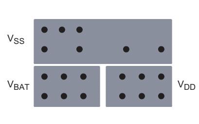
FIGURE 6-5: Typical Layout (Bottom).
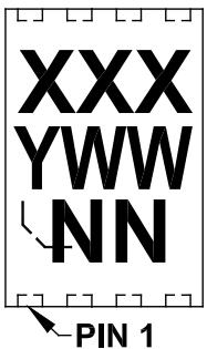
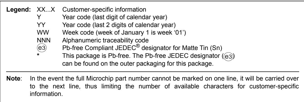
| Legend: | XX...X | Customer-specific information |
| Y | Year code (last digit of calendar year) | |
| YY | Year code (last 2 digits of calendar year) | |
| WW | Week code (week of January 1 is week ‘01’) | |
| NNN | Alphanumeric traceability code | |
| (e3) | Pb-free Compliant JEDEC® designator for Matte Tin (Sn) | |
| * | This package is Pb-free. The Pb-free JEDEC designator (e3) can be found on the outer packaging for this package. | |
| Note: | In the event the full Microchip part number cannot be marked on one line, it will be carried over to the next line, thus limiting the number of available characters for customer-specific information. | |
7.0 PACKAGING INFORMATION
7.1 Package Marking Information
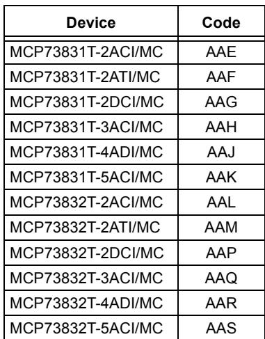
8-Lead DFN (2x3x0.9 mm)
| Device | Code |
| MCP73831T-2ACI/MC | AAE |
| MCP73831T-2ATI/MC | AAF |
| MCP73831T-2DCI/MC | AAG |
| MCP73831T-3ACI/MC | AAH |
| MCP73831T-4ADI/MC | AAJ |
| MCP73831T-5ACI/MC | AAK |
| MCP73832T-2ACI/MC | AAL |
| MCP73832T-2ATI/MC | AAM |
| MCP73832T-2DCI/MC | AAP |
| MCP73832T-3ACI/MC | AAQ |
| MCP73832T-4ADI/MC | AAR |
| MCP73832T-5ACI/MC | AAS |
Example
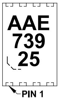
Note: Applies to 8-Lead DFN
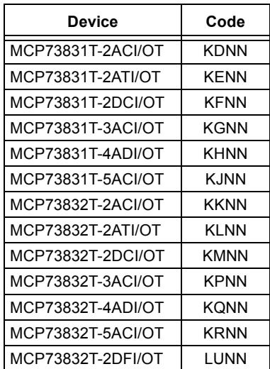
5-Lead SOT-23
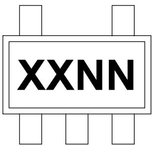
| Device | Code |
| MCP73831T-2ACI/OT | KDNN |
| MCP73831T-2ATI/OT | KENN |
| MCP73831T-2DCI/OT | KFNN |
| MCP73831T-3ACI/OT | KGNN |
| MCP73831T-4ADI/OT | KHNN |
| MCP73831T-5ACI/OT | KJNN |
| MCP73832T-2ACI/OT | KKNN |
| MCP73832T-2ATI/OT | KLNN |
| MCP73832T-2DCI/OT | KMNN |
| MCP73832T-3ACI/OT | KPNN |
| MCP73832T-4ADI/OT | KQNN |
| MCP73832T-5ACI/OT | KRNN |
| MCP73832T-2DFI/OT | LUNN |
Example
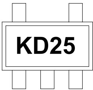
Note: Applies to 5-Lead SOT-23
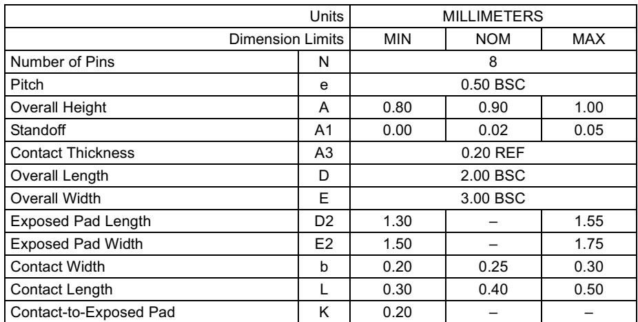
8-Lead Plastic Dual Flat, No Lead Package (MC) - 2x3x0.9 mm Body [DFN]
Note: For the most current package drawings, please see the Microchip Packaging Specification located at http://www.microchip.com/packaging
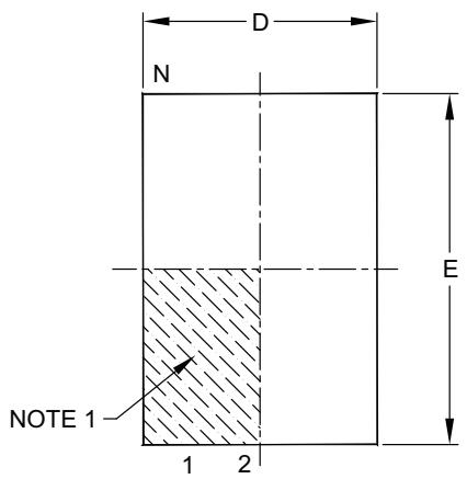
TOP VIEW
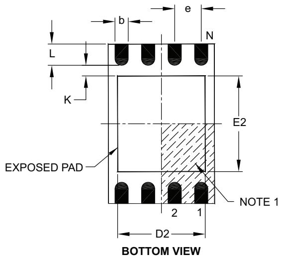
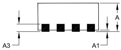
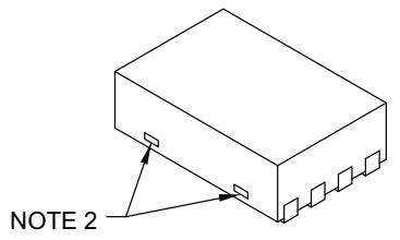
| Units | MILLIMETERS | |||
| Dimension Limits | MIN | NOM | MAX | |
| Number of Pins | N | 8 | ||
| Pitch | e | 0.50 BSC | ||
| Overall Height | A | 0.80 | 0.90 | 1.00 |
| Standoff | A1 | 0.00 | 0.02 | 0.05 |
| Contact Thickness | A3 | 0.20 REF | ||
| Overall Length | D | 2.00 BSC | ||
| Overall Width | E | 3.00 BSC | ||
| Exposed Pad Length | D2 | 1.30 | - | 1.55 |
| Exposed Pad Width | E2 | 1.50 | - | 1.75 |
| Contact Width | b | 0.20 | 0.25 | 0.30 |
| Contact Length | L | 0.30 | 0.40 | 0.50 |
| Contact-to-Exposed Pad | K | 0.20 | - | - |
Notes:
- Pin 1 visual index feature may vary, but must be located within the hatched area.
- Package may have one or more exposed tie bars at ends.
- Package is saw singulated.
- Dimensioning and tolerancing per ASME Y14.5M.
BSC: Basic Dimension. Theoretically exact value shown without tolerances.
REF: Reference Dimension, usually without tolerance, for information purposes only.
Microchip Technology Drawing C04-123C
8-Lead Plastic Dual Flat, No Lead Package (MC) - 2x3x0.9mm Body [DFN]
Note: For the most current package drawings, please see the Microchip Packaging Specification located at http://www.microchip.com/packaging
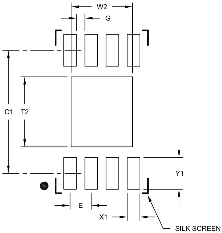
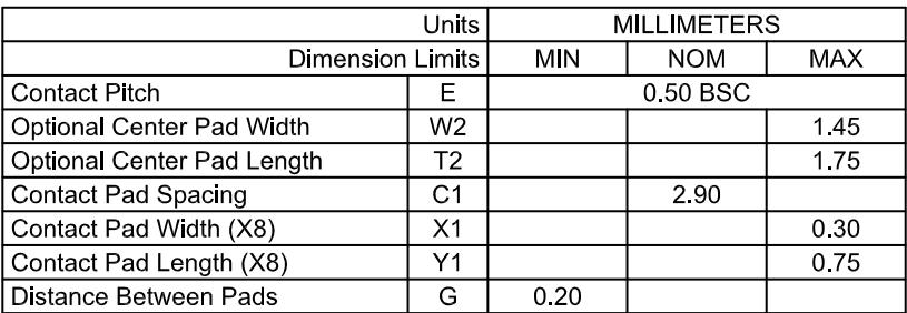
RECOMMENDED LAND PATTERN
| Units | MILLIMETERS | |||
| Dimension Limits | MIN | NOM | MAX | |
| Contact Pitch | E | 0.50 BSC | ||
| Optional Center Pad Width | W2 | 1.45 | ||
| Optional Center Pad Length | T2 | 1.75 | ||
| Contact Pad Spacing | C1 | 2.90 | ||
| Contact Pad Width (X8) | X1 | 0.30 | ||
| Contact Pad Length (X8) | Y1 | 0.75 | ||
| Distance Between Pads | G | 0.20 | ||
Notes:
- Dimensioning and tolerancing per ASME Y14.5M
BSC: Basic Dimension. Theoretically exact value shown without tolerances.
Microchip Technology Drawing No. C04-2123B
5-Lead Plastic Small Outline Transistor (OT) [SOT23]
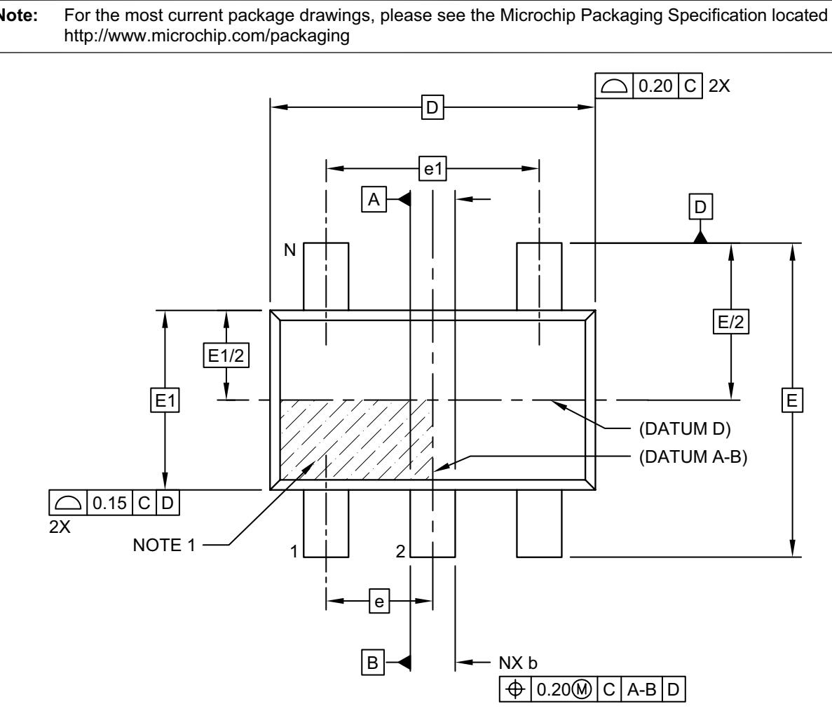
TOP VIEW
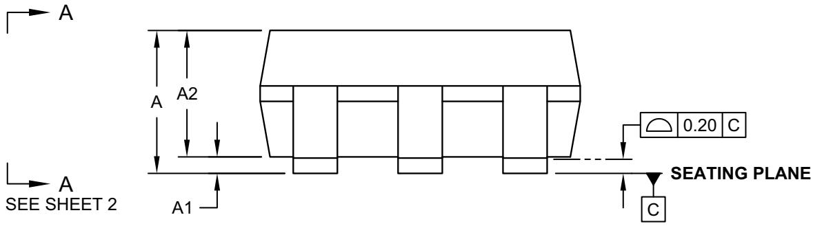
SIDE VIEW
Microchip Technology Drawing C04-091-OT Rev F Sheet 1 of 2
5-Lead Plastic Small Outline Transistor (OT) [SOT23]
Note: For the most current package drawings, please see the Microchip Packaging Specification located at http://www.microchip.com/packaging
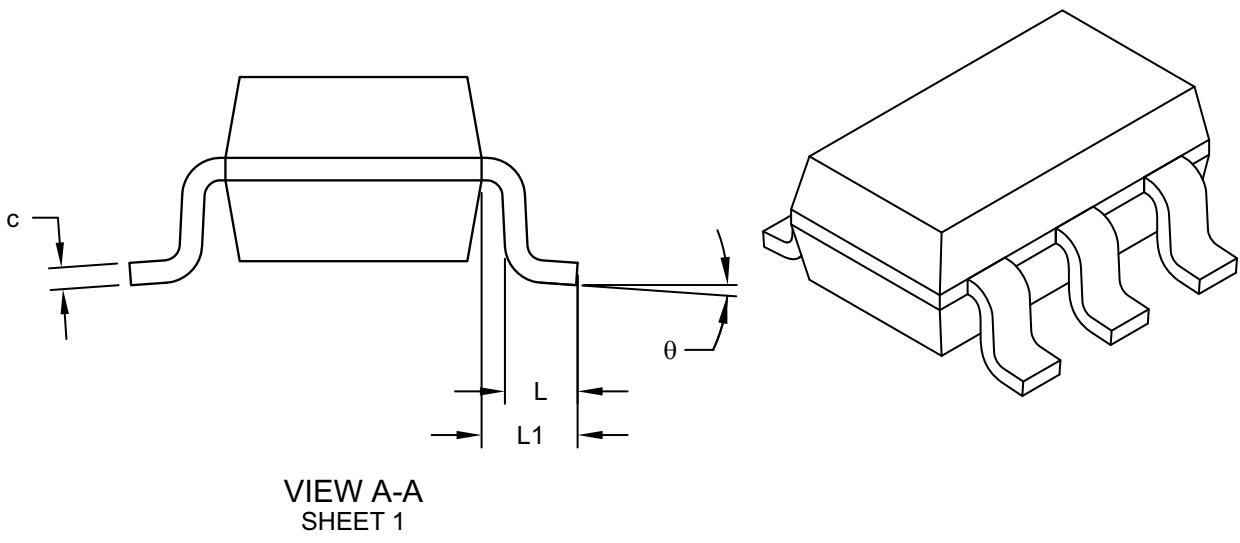
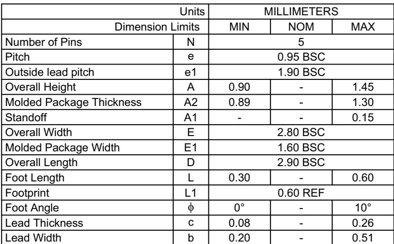
| Units | MILLIMETERS | |||
| Dimension Limits | MIN | NOM | MAX | |
| Number of Pins | N | 5 | ||
| Pitch | e | 0.95 BSC | ||
| Outside lead pitch | e1 | 1.90 BSC | ||
| Overall Height | A | 0.90 | - | 1.45 |
| Molded Package Thickness | A2 | 0.89 | - | 1.30 |
| Standoff | A1 | - | - | 0.15 |
| Overall Width | E | 2.80 BSC | ||
| Molded Package Width | E1 | 1.60 BSC | ||
| Overall Length | D | 2.90 BSC | ||
| Foot Length | L | 0.30 | - | 0.60 |
| Footprint | L1 | 0.60 REF | ||
| Foot Angle | $\phi$ | 0° | - | 10° |
| Lead Thickness | c | 0.08 | - | 0.26 |
| Lead Width | b | 0.20 | - | 0.51 |
Notes:
- Dimensions D and E1 do not include mold flash or protrusions. Mold flash or
protrusions shall not exceed 0.25mm per side. - Dimensioning and tolerancing per ASME Y14.5M
BSC: Basic Dimension. Theoretically exact value shown without tolerances.
REF: Reference Dimension, usually without tolerance, for information purposes only.
5-Lead Plastic Small Outline Transistor (OT) [SOT23]
| Note: | For the most current package drawings, please see the Microchip Packaging Specification located at http://www.microchip.com/packaging |
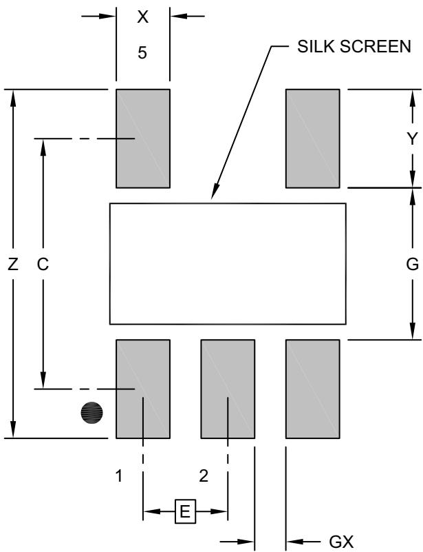
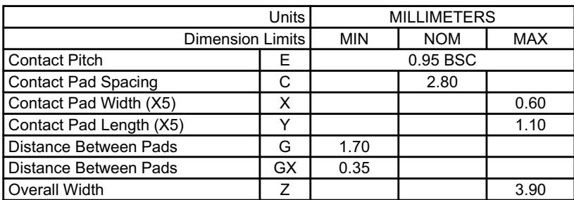
RECOMMENDED LAND PATTERN
| Units | MILLIMETERS | |||
| Dimension Limits | MIN | NOM | MAX | |
| Contact Pitch | E | 0.95 BSC | ||
| Contact Pad Spacing | C | 2.80 | ||
| Contact Pad Width (X5) | X | 0.60 | ||
| Contact Pad Length (X5) | Y | 1.10 | ||
| Distance Between Pads | G | 1.70 | ||
| Distance Between Pads | GX | 0.35 | ||
| Overall Width | Z | 3.90 | ||
Notes:
- Dimensioning and tolerancing per ASME Y14.5M
BSC: Basic Dimension. Theoretically exact value shown without tolerances.
Microchip Technology Drawing No. C04-2091-OT Rev F
APPENDIX A: REVISION HISTORY
Revision H (June 2020)
The following is the list of modifications:
Updated the Functional Block Diagram.
Updated the DC Characteristics table.
Updated the AC Characteristics table.
Updated the Temperature Specifications table.
Updated Section 4.2, Battery Detection.
Updated Figure 6-1.
Revision G (July 2014)
The following is the list of modifications:
Updated the DC Characteristics table.
Added Section 6.1.1.2, Input Overvoltage Protection (IOVP).
Revision F (June 2013)
The following is the list of modifications:
Updated the Functional Block Diagram.
Added the Battery Detection parameter and related information in the DC Characteristics table.
Added new section Section 4.2, Battery Detection.
Minor grammatical and spelling corrections.
Revision E (September 2008)
The following is the list of modifications:
Package Types: Changed DFN pinout diagram.
Section 1.0, Electrical Characteristics: Changed "Charge Impedance Range from $20\mathrm{k}\Omega$ to $67\mathrm{k}\Omega$ .
Section 1.0, Electrical Characteristics: Misc. Formatting changes.
Section 2.0, Typical Performance Curves: Updated Figure 2-4.
Section 3.0, Pin Description: Added Exposed Pad pin to table and added Section 3.6, Exposed Thermal Pad (EP).
Updated Appendix A: Revision History
Added Land Pattern Package Outline Drawing for 2x3 DFN package.
Revision D (April 2008)
The following is the list of modifications:
- Changed Charge Termination Current Ratio to 8.5% minimum and 11.5% maximum.
Revision C (October 2007)
The following is the list of modifications:
Numerous edits throughout document.
Added note to the Temperature Specifications table.
Updated Figure 2-4.
Revision B (March 2006)
The following is the list of modifications:
- Added MCP73832 through document.
Revision A (November 2005)
Original release of this document.
PRODUCT IDENTIFICATION SYSTEM
To order or obtain information, e.g., on pricing or delivery, refer to the factory or the listed sales office.
| PART NO. | X | XX | X | /XX |
| Device | VREG | Options | Temperature | Package Range |
| Device: | MCP73831: Single-Cell Charge ControllerMCP73831T: Single-Cell Charge Controller (Tape and Reel)MCP73832: Single-Cell Charge ControllerMCP73832T: Single-Cell Charge Controller (Tape and Reel) | |||
| Regulation Voltage: | Code VREG | |||
| 2 = 4.20V3 = 4.35V4 = 4.40V5 = 4.50V | ||||
| Options:* | Code IPREG/IREG VPTH/VREG ITERM/IREG VRTH/VREGAC 10 66.5 7.5 96.5AD 10 66.5 7.5 94AT 10 71.5 20 94DC 100 x 7.5 96.5* Consult Factory for Alternative Device Options | |||
| Temperature Range: | I = -40°C to +85°C (Industrial) | |||
| Package: | MC = Dual-Flat, No-Lead (2x3 mm body), 8-LeadOT = Small Outline Transistor (SOT23), 5-Lead | |||
NOTES:
Note the following details of the code protection feature on Microchip devices:
• Microchip products meet the specification contained in their particular Microchip Data Sheet.
- Microchip believes that its family of products is one of the most secure families of its kind on the market today, when used in the intended manner and under normal conditions.
- There are dishonest and possibly illegal methods used to breach the code protection feature. All of these methods, to our knowledge, require using the Microchip products in a manner outside the operating specifications contained in Microchip's Data Sheets. Most likely, the person doing so is engaged in theft of intellectual property.
• Microchip is willing to work with the customer who is concerned about the integrity of their code.
- Neither Microchip nor any other semiconductor manufacturer can guarantee the security of their code. Code protection does not mean that we are guaranteeing the product as “unbreakable.”
Code protection is constantly evolving. We at Microchip are committed to continuously improving the code protection features of our products. Attempts to break Microchip's code protection feature may be a violation of the Digital Millennium Copyright Act. If such acts allow unauthorized access to your software or other copyrighted work, you may have a right to sue for relief under that Act.
Information contained in this publication regarding device applications and the like is provided only for your convenience and may be superseded by updates. It is your responsibility to ensure that your application meets with your specifications. MICROCHIP MAKES NO REPRESENTATIONS OR WARRANTIES OF ANY KIND WHETHER EXPRESS OR IMPLIED, WRITTEN OR ORAL, STATUTORY OR OTHERWISE, RELATED TO THE INFORMATION, INCLUDING BUT NOT LIMITED TO ITS CONDITION, QUALITY, PERFORMANCE, MERCHANTABILITY OR FITNESS FOR PURPOSE. Microchip disclaims all liability arising from this information and its use. Use of Microchip devices in life support and/or safety applications is entirely at the buyer's risk, and the buyer agrees to defend, indemnify and hold harmless Microchip from any and all damages, claims, suits, or expenses resulting from such use. No licenses are conveyed, implicitly or otherwise, under any Microchip intellectual property rights unless otherwise stated.
For information regarding Microchip's Quality Management Systems, please visit www.microchip.com/quality.
Trademarks
The Microchip name and logo, the Microchip logo, Adaptec, AnyRate, AVR, AVR logo, AVR Freaks, BesTime, BitCloud, chipKIT, chipKIT logo, CryptoMemory, CryptoRF, dsPIC, FlashFlex, flexPWR, HELDO, IGLOO, JukeBlox, KeeLoq, Kleer, LANCheck, LinkMD, maXStylus, maXTouch, MediaLB, megaAVR, Microsemi, Microsemi logo, MOST, MOST logo, MPLAB, OptoLyzer, PackeTime, PIC, picoPower, PICSTART, PIC32 logo, PolarFire, Prochip Designer, QTouch, SAM-BA, SenGenuity, SpyNIC, SST, SST Logo, SuperFlash, Symmetricom, SyncServer, Tachyon, TempTrackr, TimeSource, tinyAVR, UNI/O, Vectron, and XMEGA are registered trademarks of Microchip Technology Incorporated in the U.S.A. and other countries.
APT, ClockWorks, The Embedded Control Solutions Company, EtherSynch, FlashTec, Hyper Speed Control, HyperLight Load, IntelliMOS, Libero, motorBench, mTouch, Powermite 3, Precision Edge, ProASIC, ProASIC Plus, ProASIC Plus logo, Quiet-Wire, SmartFusion, SyncWorld, Temux, TimeCesium, TimeHub, TimePictra, TimeProvider, Vite, WinPath, and ZL are registered trademarks of Microchip Technology Incorporated in the U.S.A.
Adjacent Key Suppression, AKS, Analog-for-the-Digital Age, Any Capacitor, AnyIn, AnyOut, BlueSky, BodyCom, CodeGuard, CryptoAuthentication, CryptoAutomotive, CryptoCompanion, CryptoController, dsPICDEM, dsPICDEM.net, Dynamic Average Matching, DAM, ECAN, EtherGREEN, In-Circuit Serial Programming, ICSP, INICnet, Inter-Chip Connectivity, JitterBlocker, KleerNet, KleerNet logo, memBrain, Mindi, MiWi, MPASM, MPF, MPLAB Certified logo, MPLIB, MPLINK, MultiTRAK, NetDetach, Omniscient Code Generation, PICDEM, PICDEM.net, PICkit, PICtail, PowerSmart, PureSilicon, QMatrix, REAL ICE, Ripple Blocker, SAM-ICE, Serial Quad I/O, SMART-I.S., SQI, SuperSwitcher, SuperSwitcher II, Total Endurance, TSHARC, USBCheck, VariSense, ViewSpan, WiperLock, Wireless DNA, and ZENA are trademarks of Microchip Technology Incorporated in the U.S.A. and other countries.
SQTP is a service mark of Microchip Technology Incorporated in the U.S.A.
The Adaptec logo, Frequency on Demand, Silicon Storage Technology, and Symmcom are registered trademarks of Microchip Technology Inc. in other countries.
GestIC is a registered trademark of Microchip Technology Germany II GmbH & Co. KG, a subsidiary of Microchip Technology Inc., in other countries.
All other trademarks mentioned herein are property of their respective companies.
© 2005-2020, Microchip Technology Incorporated, All Rights Reserved.
ISBN: 978-1-5224-6185-2
AMERICAS
Corporate Office
2355 West Chandler Blvd.
Chandler, AZ 85224-6199
Tel: 480-792-7200
Fax: 480-792-7277
Technical Support:
http://www.microchip.com/support
Web Address:
www.microchip.com
Atlanta
Duluth, GA
Tel: 678-957-9614
Fax: 678-957-1455
Austin, TX
Tel: 512-257-3370
Boston
Westborough, MA
Tel: 774-760-0087
Fax: 774-760-0088
Chicago
Itasca, IL
Tel: 630-285-0071
Fax: 630-285-0075
Dallas
Addison, TX
Tel: 972-818-7423
Fax: 972-818-2924
Detroit
Novi, MI
Tel: 248-848-4000
Houston, TX
Tel: 281-894-5983
Indianapolis
Noblesville, IN
Tel: 317-773-8323
Fax: 317-773-5453
Tel: 317-536-2380
Worldwide Sales and Service
Los Angeles
Mission Viejo, CA
Tel: 949-462-9523
Fax: 949-462-9608
Tel: 951-273-7800
Raleigh, NC
Tel: 919-844-7510
New York, NY
Tel: 631-435-6000
San Jose, CA
Tel: 408-735-9110
Tel: 408-436-4270
Canada - Toronto
Tel: 905-695-1980
Fax: 905-695-2078
ASIA/PACIFIC
Australia - Sydney
Tel: 61-2-9868-6733
China - Beijing
Tel: 86-10-8569-7000
China - Chengdu
Tel: 86-28-8665-5511
China - Chongqing
Tel: 86-23-8980-9588
China - Dongguan
Tel: 86-769-8702-9880
China - Guangzhou
Tel: 86-20-8755-8029
China - Hangzhou
Tel: 86-571-8792-8115
China - Hong Kong SAR
Tel: 852-2943-5100
China - Nanjing
Tel: 86-25-8473-2460
China - Qingdao
Tel: 86-532-8502-7355
China - Shanghai
Tel: 86-21-3326-8000
China - Shenyang
Tel: 86-24-2334-2829
China - Shenzhen
Tel: 86-755-8864-2200
China - Suzhou
Tel: 86-186-6233-1526
China - Wuhan
Tel: 86-27-5980-5300
China - Xian
Tel: 86-29-8833-7252
China - Xiamen
Tel: 86-592-2388138
China - Zhuhai
Tel: 86-756-3210040
ASIA/PACIFIC
India - Bangalore
Tel: 91-80-3090-4444
India - New Delhi
Tel: 91-11-4160-8631
India - Pune
Tel: 91-20-4121-0141
Japan - Osaka
Tel: 81-6-6152-7160
Japan - Tokyo
Tel: 81-3-6880-3770
Korea - Daegu
Tel: 82-53-744-4301
Korea - Seoul
Tel: 82-2-554-7200
Malaysia - Kuala Lumpur
Tel: 60-3-7651-7906
Malaysia - Penang
Tel: 60-4-227-8870
Philippines - Manila
Tel: 63-2-634-9065
Singapore
Tel: 65-6334-8870
Taiwan - Hsin Chu
Tel: 886-3-577-8366
Taiwan - Kaohsiung
Tel: 886-7-213-7830
Taiwan - Taipei
Tel: 886-2-2508-8600
Thailand - Bangkok
Tel: 66-2-694-1351
Vietnam - Ho Chi Minh
Tel: 84-28-5448-2100
EUROPE
Austria - Wels
Tel: 43-7242-2244-39
Fax: 43-7242-2244-393
Denmark - Copenhagen
Tel: 45-4485-5910
Fax: 45-4485-2829
Finland - Espoo
Tel: 358-9-4520-820
France - Paris
Tel: 33-1-69-53-63-20
Fax: 33-1-69-30-90-79
Germany - Garching
Tel: 49-8931-9700
Germany - Haan
Tel: 49-2129-3766400
Germany - Heilbronn
Tel: 49-7131-72400
Germany - Karlsruhe
Tel: 49-721-625370
Germany - Munich
Tel: 49-89-627-144-0
Fax: 49-89-627-144-44
Germany - Rosenheim
Tel: 49-8031-354-560
Israel - Ra'anana
Tel: 972-9-744-7705
Italy - Milan
Tel: 39-0331-742611
Fax: 39-0331-466781
Italy - Padova
Tel: 39-049-7625286
Netherlands - Drunen
Tel: 31-416-690399
Fax: 31-416-690340
Norway - Trondheim
Tel: 47-7288-4388
Poland - Warsaw
Tel: 48-22-3325737
Romania - Bucharest
Tel: 40-21-407-87-50
Spain - Madrid
Tel: 34-91-708-08-90
Fax: 34-91-708-08-91
Sweden - Gothenberg
Tel: 46-31-704-60-40
Sweden - Stockholm
Tel: 46-8-5090-4654
UK - Wokingham
Tel: 44-118-921-5800
Fax: 44-118-921-5820
Figures and diagrams from the PDF
Preview the extracted datasheet assets and open any image in a separate tab for closer inspection.

Use this datasheet from any agent
Send the page, markdown, chunks, or search endpoint to ChatGPT, Claude, embedr-app, or your own tooling.