
NodeMCU v2 Shield/Carrier Footprint
Carrier/socket footprint and pin map for the NodeMCU DEVKIT V1.0 / NodeMCU 1.0 ESP-12E development board header pattern. Models the assembled NodeMCU board placed on a PCB, not the bare ESP8266 MCU or ESP-12 module land pattern.
| A | 1 | 2 | 3 | 4 |
| NODE MCU DEVKIT V1.0 | ||||
| B | ||||
| C | ||||
| D | ||||
ESP-12 CORE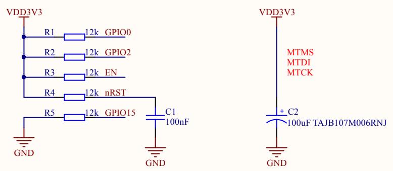
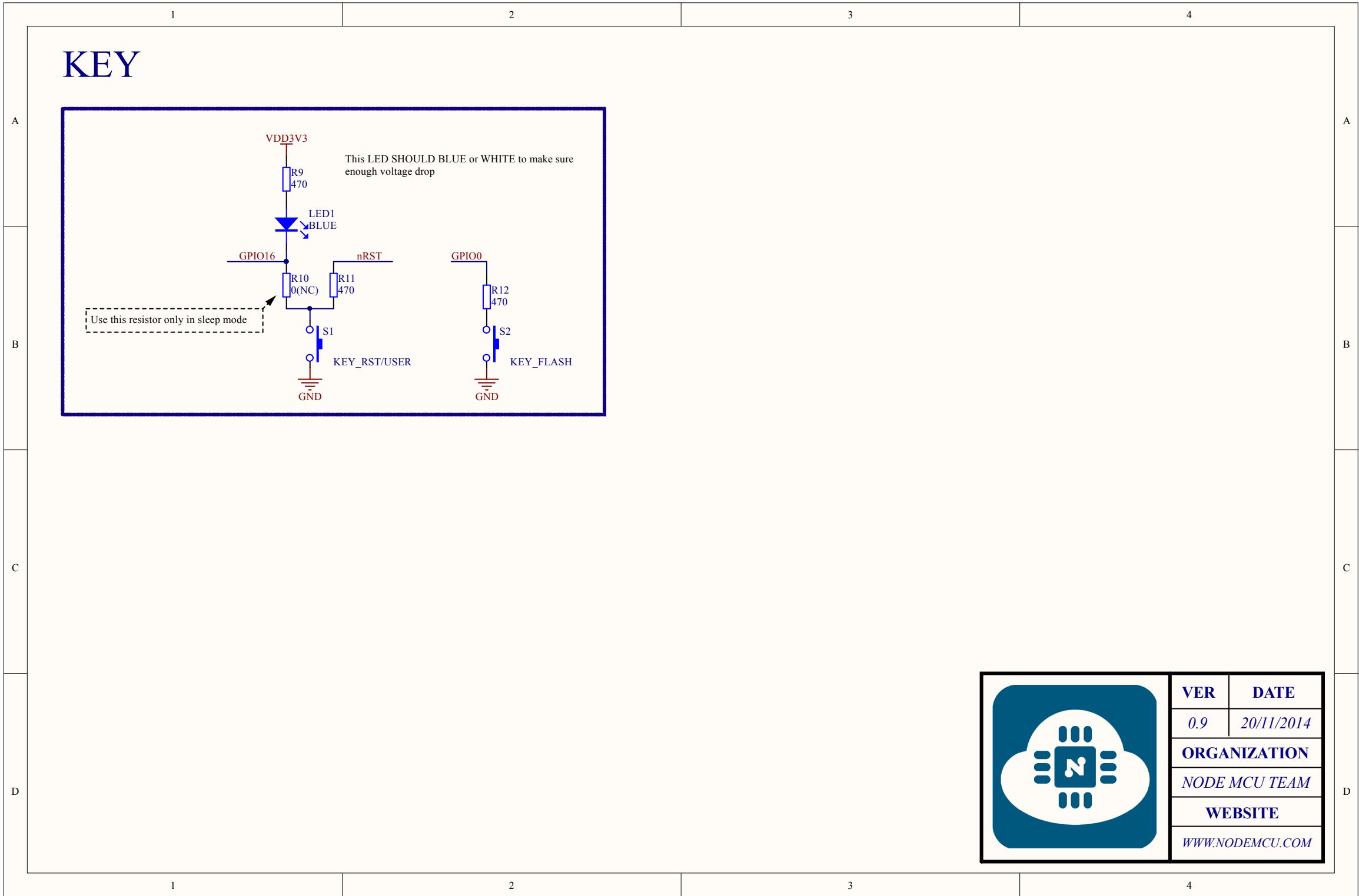
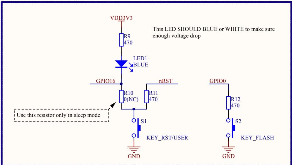
MATTERS NEEDING ATTENTION On every boot/reset/wakeup, GPIO15 MUST keep LOW, GPIO2 MUST keep HIGH. GPIO0 HIGH ->RUN MODE, LOW -> FLASH MODE. When you need to use the sleep mode,GPIO16 and RST should be connected, and GPIO16 will output LOW to reset the system at the time of wakeup
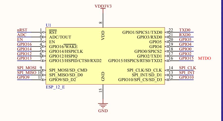
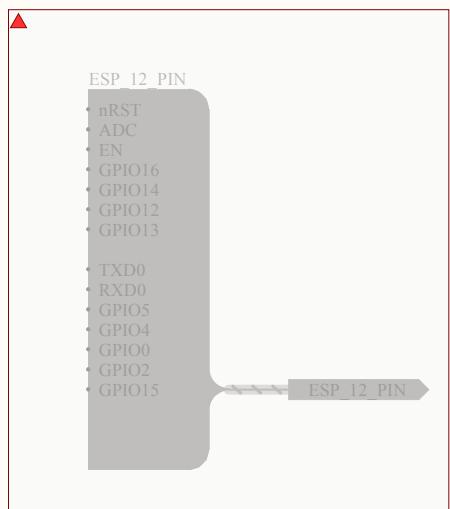

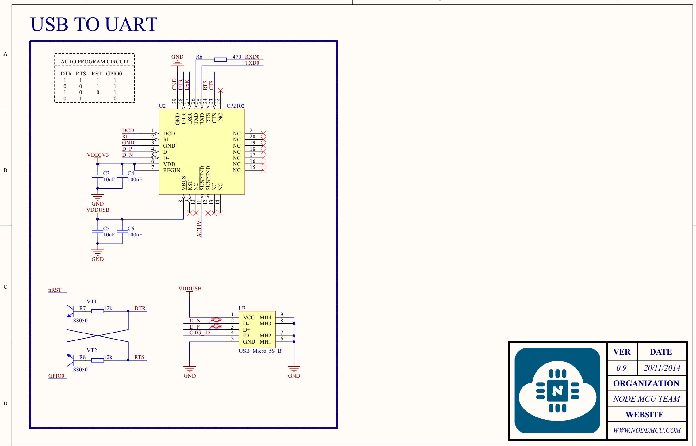
| USB TO UART | |
| [A] | |
| [B] | |
| [C] | |
| [D] | |
| 1 | 2 | 3 | 4 |
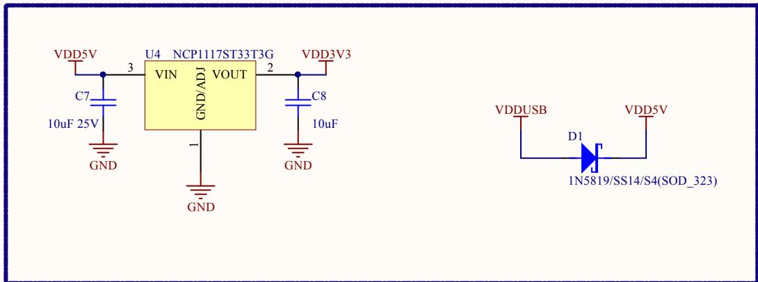
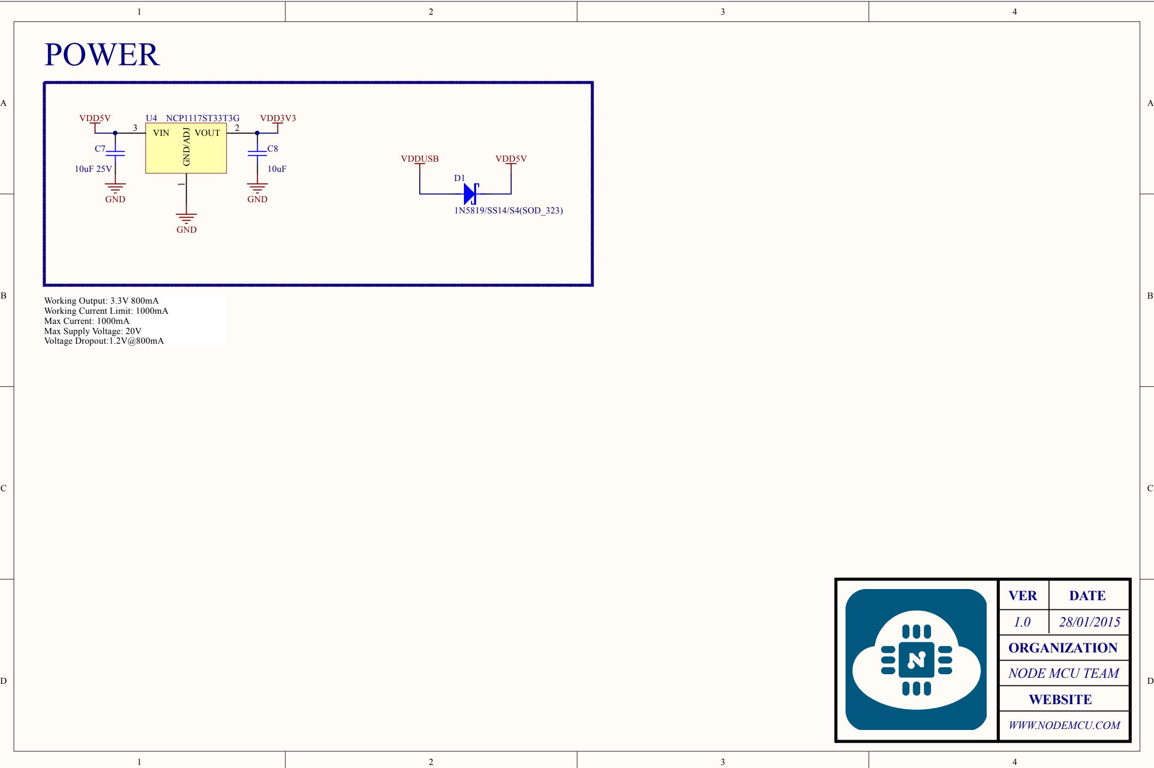
| POWER | |||
| A | <img src="./images/ee2ff9e16e356af249a1cea6d0ef137fff29d5fbb8829f7330309f71747e89e9.jpg"/> | ||
| B | Working Output: 3.3V 800mA Working Current Limit: 1000mA Max Current: 1000mA Max Supply Voltage: 20V Voltage Dropout: 1.2V@800mA | ||
| C | |||
| D | [VER] | DATE | |
| 1.0 | 28/01/2015 | ||
| ORGANIZATION | |||
| NODE MCU TEAM | |||
| WEBSITE | |||
| WWW.NODEMCU.COM | |||
| 1 | 2 | 3 | 4 | |||||||||||
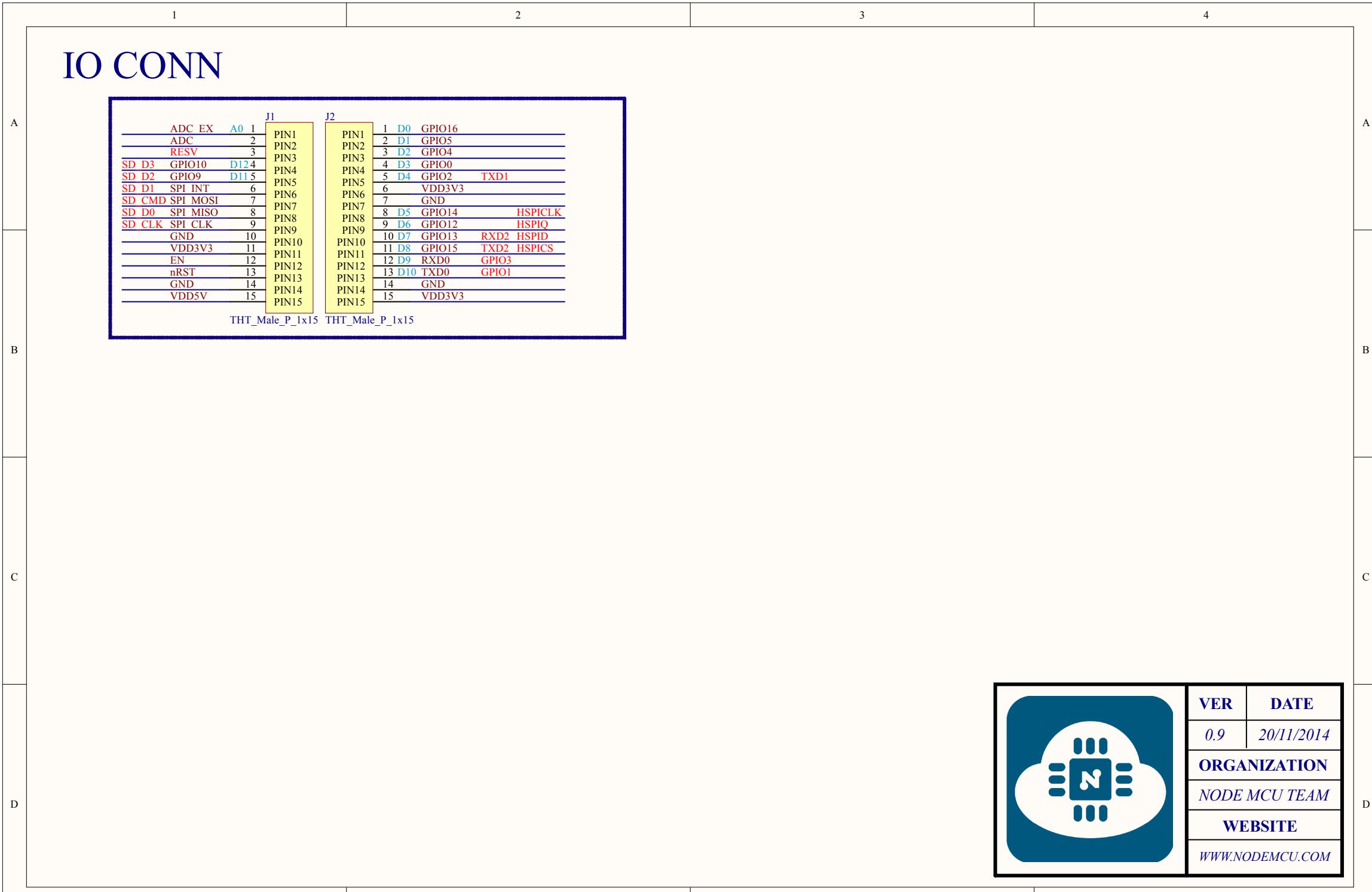
| IO CONN | ||||||||||||||
| A | ADC EX A0 1 | J1 | J2 | 1 D0 GPIO16 | ||||||||||
| ADC | 2 | PIN1 | PIN1 | 2 D1 GPIO5 | ||||||||||
| RESV | 3 | PIN2 | PIN2 | 3 D2 GPIO4 | ||||||||||
| SD D3 | GPIO10 | D124 | PIN3 | PIN3 | 4 D3 GPIO0 | |||||||||
| SD D2 | GPIO9 | D115 | PIN4 | PIN4 | 5 D4 GPIO2 TXD1 | |||||||||
| SD D1 | SPI INT | 6 | PIN5 | PIN5 | 6 VDD3V3 | |||||||||
| SD CMD | SPI MOSI | 7 | PIN6 | PIN6 | 7 GND | |||||||||
| SD D0 | SPI MISO | 8 | PIN7 | PIN7 | 8 D5 GPIO14 HSPICLK | |||||||||
| SD CLK | SPI CLK | 9 | PIN8 | PIN8 | 9 D6 GPIO12 HSPIQ | |||||||||
| B | GND | 10 | PIN9 | PIN9 | PIN9 | 10 D7 GPIO13 RXD2 HSPID | ||||||||
| VDD3V3 | 11 | PIN10 | PIN10 | PIN10 | 11 D8 GPIO15 TXD2 HSPICS | |||||||||
| EN | 12 | PIN11 | PIN11 | PIN11 | 12 D9 RXD0 GPIO3 | |||||||||
| nRST | 13 | PIN12 | PIN12 | PIN12 | 13 D10 TXD0 GPIO1 | |||||||||
| GND | 14 | PIN13 | PIN13 | PIN13 | 14 GND | |||||||||
| VDD5V | 15 | PIN14 | PIN14 | PIN14 | 15 VDD3V3 | |||||||||
| PIN15 | PIN15 | PIN15 | ||||||||||||
| THT_Male_P_1x15 THT_Male_P_1x15 | ||||||||||||||
| C | ||||||||||||||
| D | ||||||||||||||
| 1 | 2 | 3 | 4 |
| 1 | 2 | 3 | 4 | |
| KEY | ||||
| A | <img src="./images/f3ffb6a1289fd38376b84a75c276c2d4e7a54e8e6fb53bce948154c85e90ddc3.jpg"/> | |||
| B | ||||
| C | ||||
| D | ||||
| 1 | 2 | 3 | 4 |
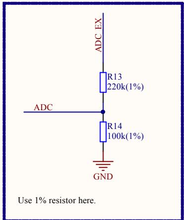
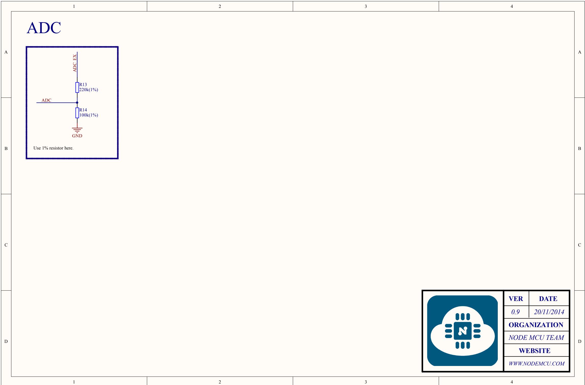
| ADC | |||
| <img src="./images/03e825ba6e0214996bd81402b63a5b9f9037ca2be575a2977e2ed2643e683439.jpg"/> | |||
| B | |||
| C | |||
| D | |||
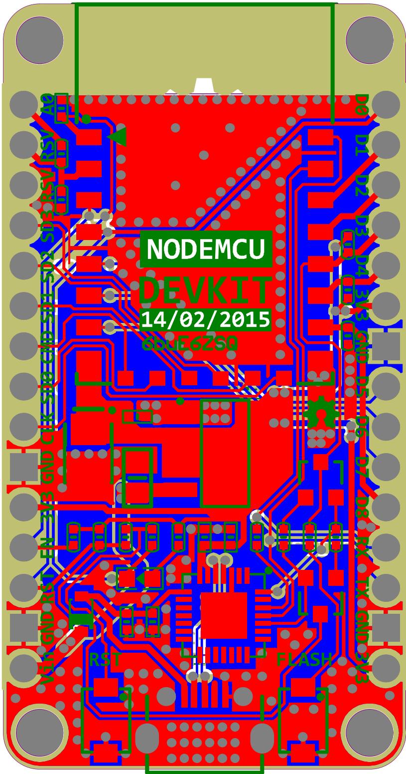
2.5400×4.8260cm
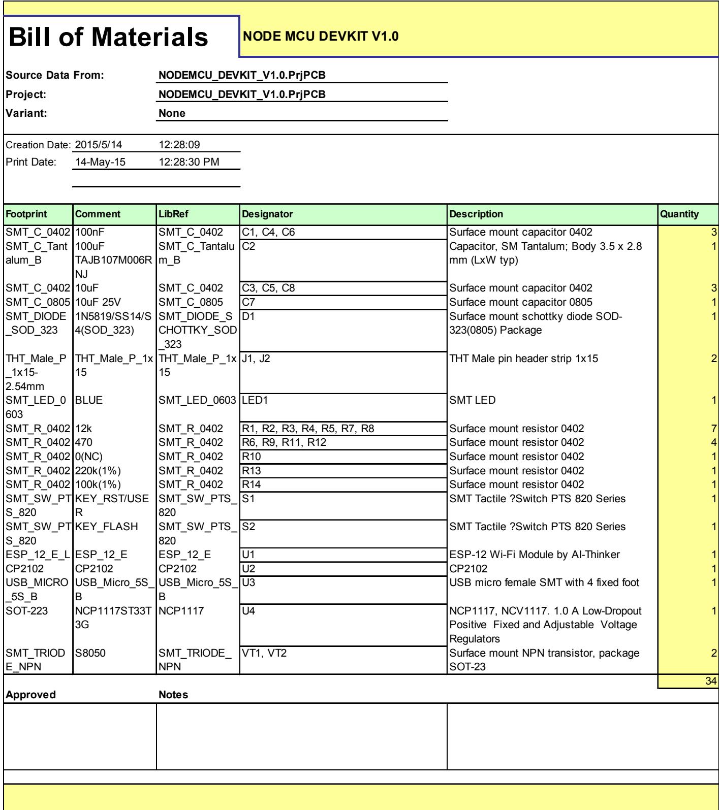
| Bill of Materials | NODE MCU DEVKIT V1.0 | ||||
| Source Data From: NODEMCU_DEVKIT_V1.0.PrjPCBProject: NODEMCU_DEVKIT_V1.0.PrjPCBVariant: None | |||||
| Creation Date: 2015/5/14 12:28:09Print Date: 14-May-15 12:28:30 PM | |||||
| Footprint | Comment | LibRef | Designator | Description | Quantity |
| SMT_C_0402 | 100nF | SMT_C_0402 | C1, C4, C6 | Surface mount capacitor 0402 | 3 |
| SMT_C_Tantalum_B | 100uF | SMT_C_Tantalum_B | C2 | Capacitor, SM Tantalum; Body 3.5 x 2.8 mm (LxW typ) | 1 |
| TAJB107M006R NJ | |||||
| SMT_C_0402 | 10uF | SMT_C_0402 | C3, C5, C8 | Surface mount capacitor 0402 | 3 |
| SMT_C_0805 | 10uF 25V | SMT_C_0805 | C7 | Surface mount capacitor 0805 | 1 |
| SMT_DIODE_SOD_323 | 1N5819/SS14/S4(SOD_323) | SMT_DIODE_SCHOTTKY_SOD_323 | D1 | Surface mount schottky diode SOD-323(0805) Package | 1 |
| THT_Male_P_1x15-2.54mm | THT_Male_P_1x15 | THT_Male_P_1x15 | J1, J2 | THT Male pin header strip 1x15 | 2 |
| SMT_LED_0603 | BLUE | SMT_LED_0603 | LED1 | SMT LED | 1 |
| SMT_R_0402 | 12k | SMT_R_0402 | R1, R2, R3, R4, R5, R7, R8 | Surface mount resistor 0402 | 7 |
| SMT_R_0402 | 470 | SMT_R_0402 | R6, R9, R11, R12 | Surface mount resistor 0402 | 4 |
| SMT_R_0402 | 0(NC) | SMT_R_0402 | R10 | Surface mount resistor 0402 | 1 |
| SMT_R_0402 | 220k(1%) | SMT_R_0402 | R13 | Surface mount resistor 0402 | 1 |
| SMT_R_0402 | 100k(1%) | SMT_R_0402 | R14 | Surface mount resistor 0402 | 1 |
| SMT_SW_PTS_820 | KEY_RST/USER | SMT_SW_PTS_820 | S1 | SMT Tactile ?Switch PTS 820 Series | 1 |
| SMT_SW_PTS_820 | KEY_FLASH | SMT_SW_PTS_820 | S2 | SMT Tactile ?Switch PTS 820 Series | 1 |
| ESP_12_E_L | ESP_12_E | ESP_12_E | U1 | ESP-12 Wi-Fi Module by AI-Thinker | 1 |
| CP2102 | CP2102 | CP2102 | U2 | CP2102 | 1 |
| USB_MICRO_5S_B | USB_Micro_5S_B | USB_Micro_5S_B | U3 | USB micro female SMT with 4 fixed foot | 1 |
| SOT-223 | NCP1117ST33T3G | NCP1117 | U4 | NCP1117, NCV1117. 1.0 A Low-Dropout Positive Fixed and Adjustable Voltage Regulators | 1 |
| SMT_TRIODE_NPN | S8050 | SMT_TRIODE_NPN | VT1, VT2 | Surface mount NPN transistor, package SOT-23 | 2 |
| Approved Notes | 34 | ||||
Figures and diagrams from the PDF
Preview the extracted datasheet assets and open any image in a separate tab for closer inspection.


Use this datasheet from any agent
Send the page, markdown, chunks, or search endpoint to ChatGPT, Claude, embedr-app, or your own tooling.