
SL353HT
Micropower omnipolar digital Hall-effect sensor IC with high duty cycle and low power consumption.

Micropower Omnipolar Digital Hall-effect Sensor ICs SL353 Series
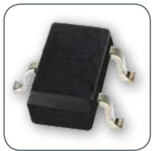
Micropower Omnipolar Digital Hall-effect Sensor ICs
Micropower Omnipolar Digital Hall-effect Sensor ICs, SL353 Series, are small, and versatile, digital Hall-effect devices operated by the magnetic field from a permanent magnet or an electromagnet. These sensitive devices are designed to meet a wide range of potential applications with low power requirements including battery-operated equipment.
The SL353 Series devices respond to either a North or South Pole, meaning that they do not require the magnet polarity to be identified, providing an easier installation and potentially reducing system cost.
These low-power sensing devices use BiCMOS (Bipolar Complementary Metal Oxide Semiconductor) technology and a timing circuit that turns the power on for only a short time – it is off for the rest of the period (duty cycle) – significantly reducing the average current consumption.
Micropower omnipolar digital Hall-effect sensor ICs can operate from a supply voltage as low as 2.2 V, promoting energy efficiency.
The push-pull output does not require a pull-up resistor and can operate with very low current levels, potentially helping to reduce cost and minimizing the total current consumption.
The SL353 Series is available in two duty cycle configurations to accommodate a variety of application needs:
• SL353HT: High duty cycle (13 % typ.) for applications requiring high switching speed and a lower current (0.33 mA typ.) than standard Hall-effect sensor ICs.
• SL353LT: Very low duty cycle (0.013 % typ.) resulting in extended battery life in applications requiring extremely low current drain (1.8 µA typ.) and not requiring a high switching speed.
The SL353 Series has a typical operating point of ±60 Gauss at 25 °C [77 °F].
These sensors are available in a subminiature SOT-23 surface mount package on tape and reel (3000 units per reel), for use in automated pick-and-place component installation.
What makes our sensors better?
Energy efficient
Supply voltage as low as 2.2 Vdc, combined with very low average current (1.8 μA typ. for SL353LT the lowest in its class), reduces power consumption, provides extended battery life, and promotes energy efficiency.
Push-pull output does not require external pull-up resistor Simplifies interface with common electrical circuits and likely reducing PCB (Printed Circuit Board) space and costs to the customer.
Non-chopper stabilized design
Does not utilize chopper stabilization, eliminating the noise generated by products using this technique. Customers do not need filters to eliminate the chopper noise, helping to reduce PCB (Printed Circuit Board space, part counts, and costs for the application.
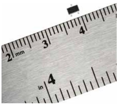
Features and Benefits
Versatile
Omnipolar capability with high-duty and low-duty cycle options allows for use in a variety of potential applications with low power requirements and/or battery operations.
Stable
Thermally balanced integrated circuit provides for stable operation over a wide temperature range, from -40 °C to 85 °C [-40 °F to 185 °F].
Offers value-priced solution
Price competitive
By using BiCMOS technology, Honeywell has been able to design a full-featured integrated circuit with reduced size, saving on manufacturing costs, and resulting in more economica pricing to customers.
Helps reduce total system cost
SL353 Series Hall-effect sensor ICs can be operated by a North Pole or a South Pole. They do not require the magnet polarity to be identified, thus making the installation easier and potentially reducing the system cost
Reduces manufacturing costs
SL353 Series is supplied on tape and reel, allowing for automated, pick-and-place assembly which can help the customer reduce manufacturing costs.
Does not require external components
The push-pull output does not require a pull-up resistor, potentially helping to reduce component and PCB (Printed Circuit Board) cost.
RoHs-compliant materials meet Directive 2002/95/EC
Potential Applications

Battery-operated, mobile equipment
• Door or lid closure detection in computer notebooks, scanners, hand-held industrial computers and instrumentation
• Mobile printer head position sensing
• Small, hand-held medical and dental equipment
• Trigger switch for battery-operated hand tools (e.g. drills, drivers)
• Reed switch replacement in battery-operated security systems
• Magnetic encoder for building access (array)
• Power switch or open-close detection in small battery-operated appliances (e.g. vacuum cleaners, fans)
• Gas or water consumption measurement in remote, battery-operated utility meters
SL353 Series
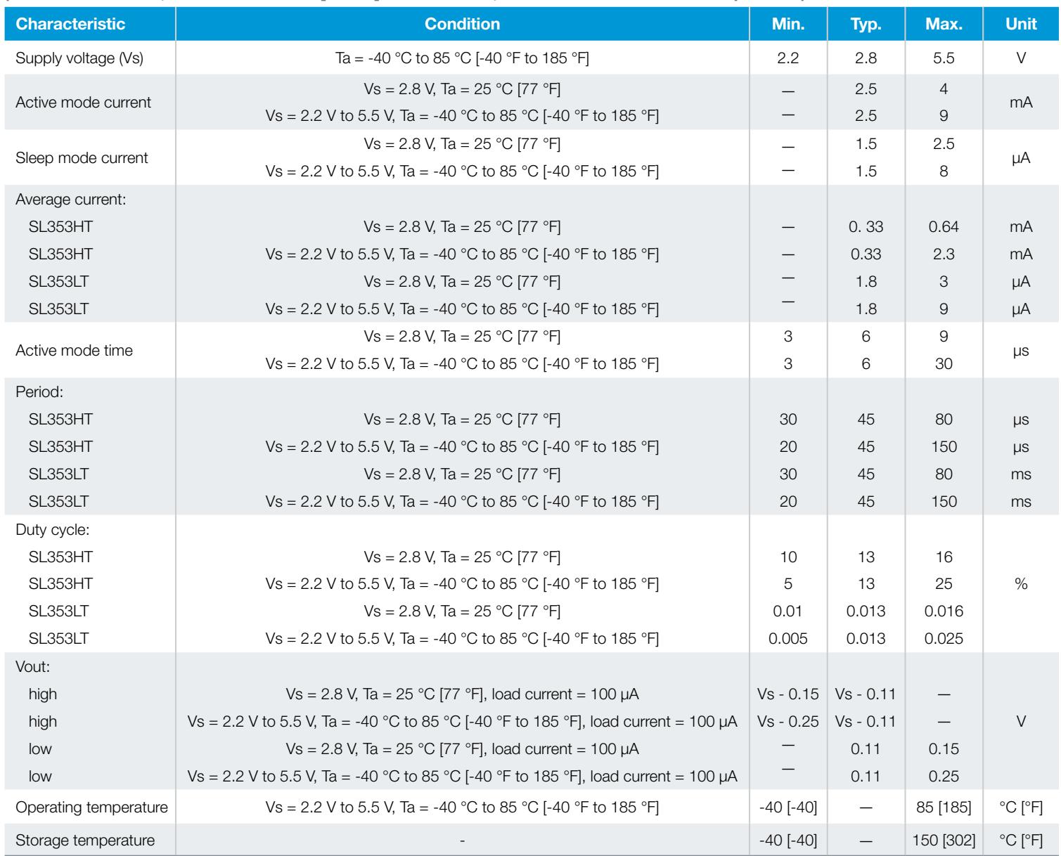
Table 1. Electrical and Environmental Characteristics for SL353 Series
(At 2.2 V $\leq V _ { 5 } \leq 5 . 5 V , - 4 0 ^ { \circ } C \leq \mathsf { T a } \leq 8 5 ^ { \circ } C$ [185 °F] and ${ \mathsf { V } } { \mathsf { S } } = 2 . 8 { \mathsf { V } } , { \mathsf { T a } } = 2 5 ^ { \circ } { \mathsf { C } }$ unless otherwise specified.)
| Characteristic | Condition | Min. | Typ. | Max. | Unit |
| Supply voltage (Vs) | Ta = -40 °C to 85 °C [-40 °F to 185 °F] | 2.2 | 2.8 | 5.5 | V |
| Active mode current | Vs = 2.8 V, Ta = 25 °C [77 °F] | — | 2.5 | 4 | mA |
| Vs = 2.2 V to 5.5 V, Ta = -40 °C to 85 °C [-40 °F to 185 °F] | — | 2.5 | 9 | ||
| Sleep mode current | Vs = 2.8 V, Ta = 25 °C [77 °F] | — | 1.5 | 2.5 | μA |
| Vs = 2.2 V to 5.5 V, Ta = -40 °C to 85 °C [-40 °F to 185 °F] | — | 1.5 | 8 | ||
| Average current: | |||||
| SL353HT | Vs = 2.8 V, Ta = 25 °C [77 °F] | — | 0.33 | 0.64 | mA |
| SL353HT | Vs = 2.2 V to 5.5 V, Ta = -40 °C to 85 °C [-40 °F to 185 °F] | — | 0.33 | 2.3 | mA |
| SL353LT | Vs = 2.8 V, Ta = 25 °C [77 °F] | — | 1.8 | 3 | μA |
| SL353LT | Vs = 2.2 V to 5.5 V, Ta = -40 °C to 85 °C [-40 °F to 185 °F] | — | 1.8 | 9 | μA |
| Active mode time | Vs = 2.8 V, Ta = 25 °C [77 °F] | 3 | 6 | 9 | μs |
| Vs = 2.2 V to 5.5 V, Ta = -40 °C to 85 °C [-40 °F to 185 °F] | 3 | 6 | 30 | ||
| Period: | |||||
| SL353HT | Vs = 2.8 V, Ta = 25 °C [77 °F] | 30 | 45 | 80 | μs |
| SL353HT | Vs = 2.2 V to 5.5 V, Ta = -40 °C to 85 °C [-40 °F to 185 °F] | 20 | 45 | 150 | μs |
| SL353LT | Vs = 2.8 V, Ta = 25 °C [77 °F] | 30 | 45 | 80 | ms |
| SL353LT | Vs = 2.2 V to 5.5 V, Ta = -40 °C to 85 °C [-40 °F to 185 °F] | 20 | 45 | 150 | ms |
| Duty cycle: | |||||
| SL353HT | Vs = 2.8 V, Ta = 25 °C [77 °F] | 10 | 13 | 16 | |
| SL353HT | Vs = 2.2 V to 5.5 V, Ta = -40 °C to 85 °C [-40 °F to 185 °F] | 5 | 13 | 25 | % |
| SL353LT | Vs = 2.8 V, Ta = 25 °C [77 °F] | 0.01 | 0.013 | 0.016 | |
| SL353LT | Vs = 2.2 V to 5.5 V, Ta = -40 °C to 85 °C [-40 °F to 185 °F] | 0.005 | 0.013 | 0.025 | |
| Vout: | |||||
| high | Vs = 2.8 V, Ta = 25 °C [77 °F], load current = 100 μA | Vs - 0.15 | Vs - 0.11 | — | |
| high | Vs = 2.2 V to 5.5 V, Ta = -40 °C to 85 °C [-40 °F to 185 °F], load current = 100 μA | Vs - 0.25 | Vs - 0.11 | — | V |
| low | Vs = 2.8 V, Ta = 25 °C [77 °F], load current = 100 μA | — | 0.11 | 0.15 | |
| low | Vs = 2.2 V to 5.5 V, Ta = -40 °C to 85 °C [-40 °F to 185 °F], load current = 100 μA | — | 0.11 | 0.25 | |
| Operating temperature | Vs = 2.2 V to 5.5 V, Ta = -40 °C to 85 °C [-40 °F to 185 °F] | -40 [-40] | — | 85 [185] | °C [°F] |
| Storage temperature | - | -40 [-40] | — | 150 [302] | °C [°F] |
NOTICE
These Hall-effect sensors ICs may have an initial output in either the on or off state if powered up with an applied magnetic field in the differential zone (applied magnetic field > Brp and < Bop). Honeywell recommends that the application circuit designer allow 10 μs after apply voltage has reached its rated value for the output voltage to stabilize.
The sensor will turn LOW when the magnetic field is present and switch to HIGH when the field is removed. The sensor will latch and hold the state during the sleep “mode”.
Micropower Omnipolar Digital Hall-Effect Sensor ICs
Table 2. Magnetic Characteristics for SL353 Series (2.2 V ≤ Vs ≤ 5.5 V, -40 °C [-40 °F] ≤ Ta ≤ 85 °C [185 °F])
| Characteristic | Condition | Min. | Typ. | Max. | Unit |
| Operate point (positive) | Vs = 2.2 V to 5.5 V, Ta = -40 °C to 85 °C [-40 °F to 185 °F] | 20 | 60 | 110 | Gauss |
| Operate point (negative) | Vs = 2.2 V to 5.5 V, Ta = -40 °C to 85 °C [-40 °F to 185 °F] | -110 | -60 | -20 | Gauss |
| Release point (positive) | Vs = 2.2 V to 5.5 V, Ta = -40 °C to 85 °C [-40 °F to 185 °F] | 5 | 45 | 95 | Gauss |
| Release point (negative) | Vs = 2.2 V to 5.5 V, Ta = -40 °C to 85 °C [-40 °F to 185 °F] | -95 | -45 | -5 | Gauss |
| Hysteresis | Vs = 2.2 V to 5.5 V, Ta = -40 °C to 85 °C [-40 °F to 185 °F] | 3 | 15 | 60 | Gauss |
NOTICE
The magnetic field strength (Gauss) required to cause the switch to change state (operate and release) will be as specified in the magnetic characteristics. To test the switch against the specified magnetic characteristics, the switch must be placed in a uniform magnetic field.
Table 3. Absolute Maximum Ratings
| Characteristic | Condition | Min. | Typ. | Max. | Unit |
| Supply voltage | — | -0.5 | — | 6 | V |
| Operating temperature | ambient | -40 [-40] | — | 150 [302] | °C [°F] |
| Soldering temperature | applied for <10 s | — | — | 265 [509] | °C [°F] |
| Load current | — | — | — | 5 | mA |
NOTICE
These absolute maximum ratings are the extreme limits that the device will withstand without damage to the device. However, the electrical and mechanical characteristics are not guaranteed as the maximum limits (above recommended operating conditions) are approached, nor will the device necessarily operate at absolute maximum ratings.
Figure 1. Block/Electrical Diagram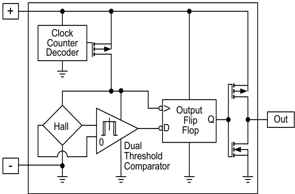
SL353 Series
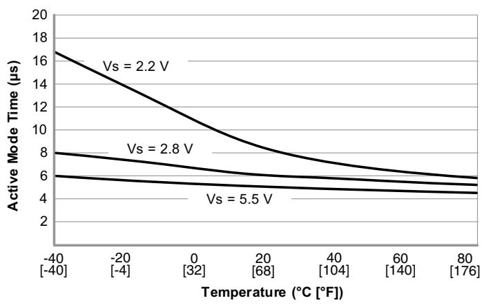
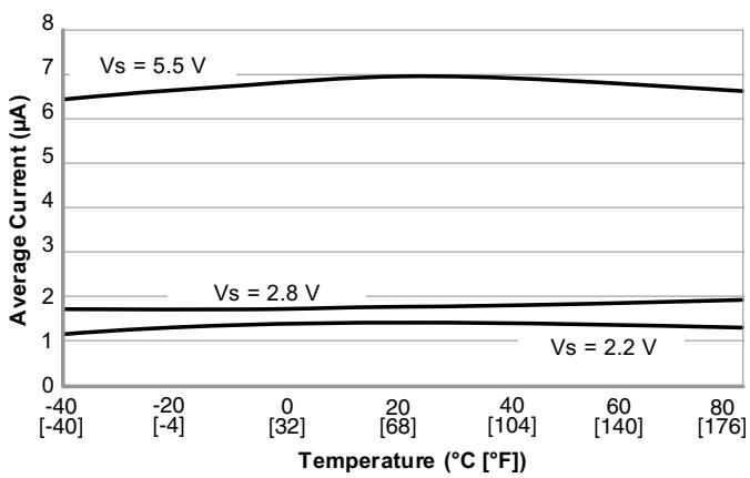
Figure 2. Typical Performance Characteristics
SL353HT and SL353LT Magnetic performance vs temperature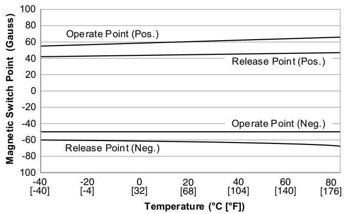
SL353HT and SL353LT Active mode time vs temperature
SL353HT and SL353LT Period vs temperature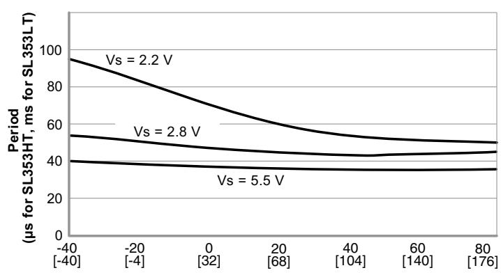
SL353HT Average current vs temperature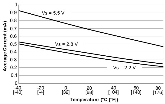
SL353LT Average current vs temperature
Micropower Omnipolar Digital Hall-Effect Sensor ICs
Figure 3. Package, Mounting and Tape/Reel Dimensions (For reference only. mm/[in].)
Sensor
Sensor Showing Polarity
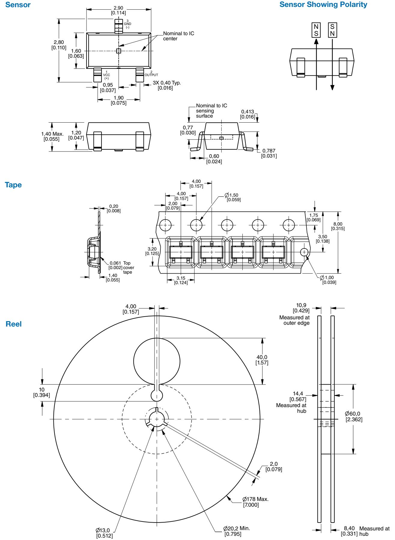
Table 4. Order Guide
| Catalog Listing | Description | |
| SL353HT | SL353 Series micropower omnipolar digital Hall-effect sensor IC, high-duty cycle, low power (0.33 mA, 2.8 Vdc), SOT-23 package, tape-and-reel packaging (3000 units per reel) | <img src="images/00e267f53e5702ee2d8aac1bc15b21657a3ed75e191b163ad63eb483bc6a964c.jpg"/> |
| SL353LT | SL353 Series micropower omnipolar digital Hall-effect sensor IC, low-duty cycle, ultra low power (1.8 μA, 2.8 Vdc), SOT-23 package, tape-and-reel packaging (3000 units per reel) | |
ADDITIONAL INFORMATION
The following associated literature is available on the Honeywell website at sensing.honeywell.com:
• Product line guide
• Product range guide
• Sensors and switches for potential medical applications
• Product installation instructions
• Application note: Shaft Encoding - Tachometer
Find out more
Honeywell serves its customers through a worldwide network of sales offices, representatives and distributors. For application assistance, current specifications, pricing or name of the nearest Authorized Distributor, contact your local sales office.
To learn more about Honeywell’s sensing and control products, call +1-815-235-6847 or 1-800-537-6945, visit sensing.honeywell.com, or e-mail inquiries to info.sc@honeywell.com
Sensing and Control Honeywell 1985 Douglas Drive North Golden Valley, MN 55422 honeywell.com
WARNING
PERSONAL INJURY
DO NOT USE these products as safety or emergency stop devices or in any other application where failure of the product could result in personal injury.
Failure to comply with these instructions could result in death or serious injury.
WARNING
MISUSE OF DOCUMENTATION
The information presented in this datasheet is for reference only. Do not use this document as a product installation guide.
Complete installation, operation, and maintenance information is provided in the instructions supplied with each product.
Failure to comply with these instructions could result in death or serious injury.
WARRANTY/REMEDY
Honeywell warrants goods of its manufacture as being free of defective materials and faulty workmanship. Honeywell’s standard product warranty applies unless agreed to otherwise by Honeywel in writing; please refer to your order acknowledgement or consult your local sales office for specific warranty details. If warranted goods are returned to Honeywell during the period of coverage, Honeywell will repair or replace, at its option, without charge those items it finds defective. The foregoing is buyer’s sole remedy and is in lieu of all other warranties, expressed or implied, including those of merchantability and fitness for a particular purpose. In no event shall Honeywell be liable for consequential, special, or indirect damages.
While we provide application assistance personally, through our literature and the Honeywell website, it is up to the customer to determine the suitability of the product in the application.
Specifications may change without notice. The information we supply is believed to be accurate and reliable as of this printing. However, we assume no responsibility for its use.
Honeywell
Figures and diagrams from the PDF
Preview the extracted datasheet assets and open any image in a separate tab for closer inspection.



Use this datasheet from any agent
Send the page, markdown, chunks, or search endpoint to ChatGPT, Claude, embedr-app, or your own tooling.