
Ebyte E22-900T22D
22 dBm 868/915 MHz LoRa wireless UART module with TTL-level serial interface, AT/HEX configuration, and SMA-K antenna connector.
Ebyte E22-T Series LoRa UART Module User Manual (EN), covering E22-900T22D
Source: Chengdu Ebyte Electronic Technology Co., Ltd., E22-T User Manual (AT/HEX command generation, copyright 2012-2026), downloaded 2026-10-23 from the E22-900T22D product page https://www.cdebyte.com/products/E22-900T22D (file https://www.cdebyte.com/pdf-down.aspx?id=4217, served as E22-T+Series+Module_UserManual_EN.pdf, 50 pages), PDF SHA-256 2c015ad5f99a58371fe02b671591245190a74126b58e089ed38f6ec54c9ef0ba.
This document is a page-by-page transcription of the PDF text layer (pdftotext -layout) together with every real figure embedded in the PDF (the logo repeated in each page header is omitted). The configured parser extracted 105 images, which exceeds the 60-image publish limit, so this faithful fallback was published instead. Mechanical drawings are images; their dimensions are transcribed in the next section.
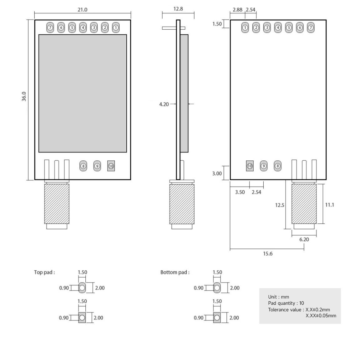
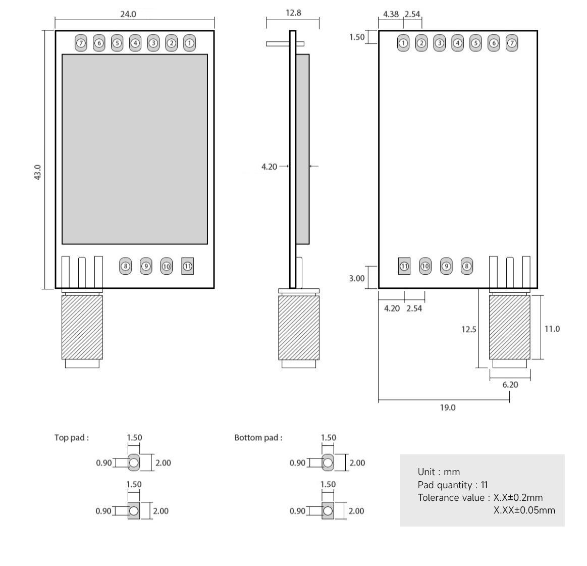
E22-900T22D drawing dimensions (transcribed from the page 10 figure, sec. 3.2)
Unit mm; tolerance X.X +/-0.2 mm, X.XX +/-0.05 mm; pad quantity 10.
| Feature | Value |
|---|---|
| Module PCB outline | 21.0 x 36.0 |
| Side-view overall depth (header pin tip to top of module) | 12.8 |
| Side-view dimension across PCB and top-side shield | 4.20 |
| Header pins 1-7 (M0, M1, RXD, TXD, AUX, VCC, GND) | single row, 2.54 pitch, row centre 1.50 from the short edge opposite the SMA |
| Pin 1 / pin 7 centre to adjacent long edge | 2.88 (bottom view: pin 1 on the left) |
| Fixed holes 8, 9, 10 | row centre 3.00 from the SMA edge; bottom view: hole 10 at 3.50 from the pin-1 long edge, then 2.54 pitch (9, 8) |
| Module pad (top and bottom) | 1.50 x 2.00 oval or square, 0.90 hole |
| SMA-K jack | 6.20 wide, projects 12.5 beyond the PCB edge (11.1 body), centre 15.6 from the pin-1 long edge (bottom view) |
Page 1

  E22-T Series Product Specifications

AT Command 230/433/868/915MHz LoRa Wireless Module
Page 2
                                                                                             E22-T User Manual


                                          Disclaimer and Copyright Notice

            The information contained herein, including the URLs for reference, is subject to change withou
     t prior notice. This document is provided "as is" without any warranties, including but not limited to
     warranties of merchantability, fitness for a particular purpose, and non-
     infringement, as well as any warranties implied by proposals, specifications, or samples mentioned el
     sewhere. The company shall not be liable for any claims, including liabilities arising from the use of
     information in this document that may infringe upon any patent rights. No intellectual property licens
     e, either express or implied, is granted herein by estoppel or otherwise.

            All test data stated in this document are obtained by Ebyte Laboratory, and actual results may va
     ry slightly.

            All trade names, trademarks and registered trademarks mentioned herein are the property of thei
     r respective owners.

            This product is strictly prohibited from being used in military applications and life safety-
     related scenarios. The user shall bear full responsibility for any unauthorized use.

            Chengdu Ebyte Electronic Technology Co., Ltd. reserves the right of final interpretation.

           Notice :

           The content of this manual may be modified due to product version upgrades or other reasons. Chengdu Ebyte Electronic Technol
     ogy Co., Ltd. reserves the right to revise the contents of this manual without prior notice. This manual is intended solely for operationa
     l guidance. While every effort has been made to ensure the accuracy of the information herein, the company does not warrant that the c
     ontent is entirely error-
     free. All statements, information and recommendations contained in this manual shall not constitute any express or implied warranties
     whatsoever.


Copyright ©2012–2026,Chengdu Ebyte Electronic Technology Co.,Ltd.                                                                           1
Page 3
                                                                                                                             E22-T User Manual


                                                                                        Contents

     E22-T Series Product Specifications ..................................................................................................................................... 0
     1 Introduction..............................................................................................................................................................................4

         1.1 Brief Introduction ....................................................................................................................................... 4
         1.2 Features .......................................................................................................................................................4
         1.3 Application ................................................................................................................................................. 5
     2 Specification............................................................................................................................................................................ 5

         2.1 E22-T Series Product Selection Comparison ............................................................................................. 5
         2.2 Basic Parameters .........................................................................................................................................6
     3 Mechanical Dimensions and Pin Definitions ...................................................................................................................8

         3.1 E22-230/400/900T22S Mechanical Dimensions and Pin Definitions ........................................................8
         3.2 E22-230/400/900T22D Mechanical Dimensions and Pin Definitions ....................................................... 9
         3.3 E22-230/400/900T30S Mechanical Dimensions and Pin Definitions ......................................................10
         3.4 E22-230/400/900T30D Mechanical Dimensions and Pin Definitions ..................................................... 12
     4 Recommended Connection Diagram...............................................................................................................................13
     5 Functions in detail ................................................................................................................................................................13

         5.1 Working Mode ..........................................................................................................................................14
         5.2 AUX Timing .............................................................................................................................................21
         5.3 Relay Networking Rules ...........................................................................................................................24
         5.4 Serial Port Firmware Upgrade .................................................................................................................. 25
     6 Register Read/Write Control ............................................................................................................................................. 26

         6.1 HEX Instruction Format ........................................................................................................................... 26
         6.2 Register Function Reference Table .......................................................................................................... 27
         6.3 Register Specificationsj ............................................................................................................................ 28
         6.4 Register Parameter Factory Default Values ............................................................................................. 31
     7 AT Commands .................................................................................................................................................................. 32

         7.1 General Command ....................................................................................................................................32
         7.2 Signaling Testing (Certification) .............................................................................................................. 41
     8 Hardware Design ..................................................................................................................................................................42

Copyright ©2012–2026,Chengdu Ebyte Electronic Technology Co.,Ltd.                                                                                                                             2
Page 4
                                                                                                                           E22-T User Manual
     9 Common problems ...............................................................................................................................................................42

         9.1 Unsatisfactory transmission distance ........................................................................................................42
         9.2 Modules are fragile ...................................................................................................................................43
         9.3 BER is too high .........................................................................................................................................43
         9.4 Antenna Selection .....................................................................................................................................43
     10 Welding instructions ......................................................................................................................................................... 44

         10.1 Reflow temperature ................................................................................................................................ 44
         10.2 Reflow temperature ................................................................................................................................ 44
     11 Related Models...................................................................................................................................................................45
     12 Antenna Guide ....................................................................................................................................................................45

         12.1 Antenna Recommendations ....................................................................................................................45
     13 Bulk packaging method....................................................................................................................................................47

         13.1 E22-230/400/900T22S Bulk Packaging Method ....................................................................................47
         13.2 E22-230/400/900T22D(30D) Bulk Packaging Method ......................................................................... 48
         13.3 E22-230/400/900T30S Bulk Packaging Method ....................................................................................48
     Revision history....................................................................................................................................................................... 49
     About us................................................................................................................................................ 错误!未定义书签。


Copyright ©2012–2026,Chengdu Ebyte Electronic Technology Co.,Ltd.                                                                                                                          3
Page 5
E22-T User Manual
1 Introduction
1.1 Brief Introduction
The E22-T series represents a new generation of LoRa wireless data transmission modules. This series of (UART)
modules is developed based on SEMTECH's high-performance RF chips, featuring a maximum transmit power of
30dBm. It supports multiple transmission modes and operates across the 230MHz, 400MHz, and 900MHz frequency
bands. Utilizing LoRa spread spectrum technology with TTL-level output, it is compatible with 3.3V I/O port voltage.
The E22-T series adopts the latest generation of LoRa spread spectrum technology, delivering faster speeds, lower
power consumption, and a more compact form factor. It supports features such as air wake-up, wireless configuration,
carrier sense, auto-relay, and communication keys. Custom packet length settings are available, and bespoke
development services can be provided.
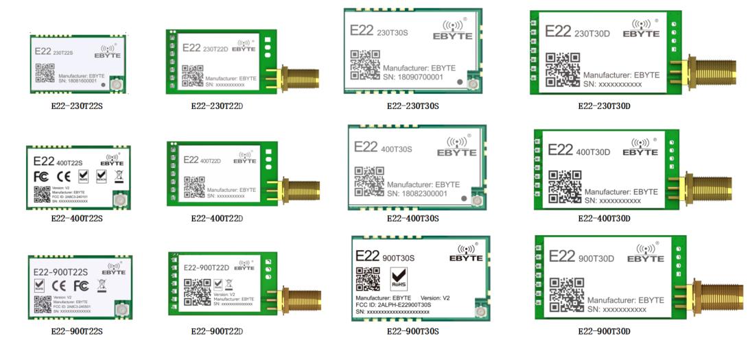
The 12 modules shown below vary in power, package, and frequency band. Detailed specifications are provided in
Section 2.1: E22-T Series Product Selection Comparison.
1.2 Features
Utilizes the latest generation LoRa spread spectrum modulation technology for extended communication range and
enhanced interference resistance;
Supports multiple frequency bands including 230/433/868/915MHz (customizable);
Supports serial port firmware upgrades for simplified maintenance;
Dual command systems (HEX/AT) for flexible user selection;
Supports relay networking with multi-level relays for ultra-long-range communication, enabling simultaneous
Copyright ©2012–2026,Chengdu Ebyte Electronic Technology Co.,Ltd. 4
Page 6
E22-T User Manual
operation of multiple networks within the same area;
Allows user-defined communication keys that cannot be read, significantly enhancing data confidentiality;
Supports LBT (Listen Before Talk) functionality to monitor channel noise before transmission, substantially
improving communication success rates in harsh environments;
Supports RSSI (Received Signal Strength Indication) for signal quality assessment;
Supports wireless parameter configuration via remote transmission of command packets to configure or read module
settings;
Supports air-to-air wake-up (ultra-low power mode) for battery-powered applications;
Supports point-to-point transmission, broadcast transmission, and channel monitoring;
Supports deep sleep mode;
Multi-level adjustable air-to-air transmission rates;
Parameters are preserved during power loss; the module resumes operation with preset parameters upon power-up;
Built-in watchdog automatically resets and restores operation in case of unexpected events.
1.3 Application
Smart agricultural irrigation and environmental monitoring;
Photovoltaic power plant monitoring and distributed PV system management;
Home security alarms and remote keyless entry;
Smart home devices and industrial sensors;
Wireless alarm security systems;
Building automation solutions;
Wireless industrial-grade remote controllers;
Healthcare products;
Advanced Metering Infrastructure (AMI).
2 Specification
2.1 E22-T Series Product Selection Comparison
Carrier Transmit Test Product Antenna
Product Package
Category frequency Power②: distance③: Dimensions Configuration
Model Type
①: Hz dBm km (mm) ④
IPEX-1/Stamp
E22-230T22S 220~236M 22 5 SMD 16*26
Hole
E22-
220~236M 22 5 DIP 21*36 SMA-K
230MHz 230T22D
Module IPEX-1/Stamp
E22-230T30S 220~236M 30 10 SMD 40.5*25
Hole
E22-
220~236M 30 10 DIP 43*24 SMA-K
230T30D
Copyright ©2012–2026,Chengdu Ebyte Electronic Technology Co.,Ltd. 5
Page 7
E22-T User Manual
Carrier Transmit Test Product Antenna
Product Package
Category frequency Power②: distance③: Dimensions Configuration
Model Type
①: Hz dBm km (mm) ④
IPEX-1/Stamp
E22-400T22S 410~493M 22 5 SMD 16*26
Hole
433MHz E22-
410~493M 22 5 DIP 21*36 SMA-K
Module 400T22D
IPEX-1/Stamp
E22-400T30S 410~493M 30 10 SMD 40.5*25
Hole
E22-
410~493M 30 10 DIP 43*24 SMA-K
400T30D
IPEX-1/Stamp
E22-900T22S 850~930M 22 5 SMD 16*26
Hole
E22-
850~930M 22 5 DIP 21*36 SMA-K
868/915MHz 900T22D
Module IPEX-1/Stamp
E22-900T30S 850~930M 30 10 SMD 40.5*25
Hole
E22-
850~930M 30 10 DIP 43*24 SMA-K
900T30D
Note:
(1) Carrier Frequency ①: Frequency band range supports user customization;
(2) Transmit Power ②: 22dBm = 158mW / 30dBm = 1000mW, tolerance range ±1dBm, multi-level power adjustable.
For detailed power levels, refer to Sections 6 and 7 of this document;
(3) Test Distance ③ : Clear open space, air speed 2.4kbps, antenna height 2 meters (for reference only; field testing
recommended);
(4) Antenna Configuration④: Equivalent impedance approximately 50Ω;
Modules within the same frequency band can communicate with each other.
2.2 Basic Parameters
E22-T Series 22dBm Low-Power Module Models: E22-230T22D, E22-230T22S, E22-400T22D, E22-400T22S, E22-
900T22D, E22-900T22S;
E22-T Series 30dBm high-power module models: E22-230T30D, E22-230T30S, E22-400T30D, E22-400T30S, E22-
900T30D, E22-900T30S;
2.2.1 Basic Parameters
Conditions: Tc=25°C, VCC=5.0V, 230MHz/433MHz/868MHz/915MHz
Parameters Description
Modulation
Next-Generation LoRa Modulation Technology
Scheme
Interface
Method 1.27mm pin header / 2.54mm header pins
Communicati
Pin header: surface-mount module
on Interface
Copyright ©2012–2026,Chengdu Ebyte Electronic Technology Co.,Ltd. 6
Page 8
                                                                                    E22-T User Manual

       Parameters                                                    Description
       Transmission
                         Header pins: through-hole module
          Length
      Package Type       UART serial port (3.3V)
          Buffer         240 bytes maximum per packet; automatically segments packets exceeding this limit. Adjustable via
         Capacity        host computer or commands. Detailed commands are provided in Section 6 of this document.
          Cache
                         1000Byte
         capacity
      Work Environment
        Operating
                         -40°C to +85°C, industrial-grade standard
       Temperature
         Operating
                         10% to 90% RH
         Humidity
         Storage
                         -40°C to +125°C
       Temperature
      Radio Frequency Parameters
         Transmit        22dBm = 158mW, multi-level power adjustable. Details in Sections 6 and 7 of this document.
          Power
                         30dBm = 1000mW, multi-level power adjustable. Details in Sections 6 and 7 of this document.
        Operating        220MHz–236MHz, supports custom frequency bands.
        Frequency
                         410MHz–493MHz, supports custom frequency bands.
          Band

         Receiver        850MHz–930MHz, supports band customization
        Sensitivity
                         -131dBm, air data rate 2.4kbps@SF11, applicable to E22-T series 22dBm low-power modules
         Data Rate       -134dBm, air data rate 2.4kbps@SF11, applicable to E22-T series 30dBm high-power modules
                         2.4–15.5Kbps, multi-level adjustable air data rate, suitable for 230MHz band modules. See Sections 6
                         and 7 of this document for details
         Blocking
          Power          2.4–62.5Kbps, multi-level adjustable air data rate, suitable for 400MHz and 900MHz band modules.
                         See Sections 6 and 7 of this document for details
         Transmit
                         10dBm
          Power
      Electrical Parameters
          Supply         2.6–5.5V, 30dBm output module ≥5V, 22dBm output module ≥3.3V ensures output power; exceeding
          Voltage        5.5V will permanently damage the module.
       Communicati
                         3.3V
         on Level
                         100–140mA, instantaneous power consumption @22dBm, suitable for E22-T series 22dBm low-power
         Transmit        modules
         Current
                         460–620mA, instantaneous power consumption @ 30dBm, suitable for E22-T series 30dBm high-
                         power modules
          Receive        ≈7mA, suitable for E22-T series 22dBm low-power modules
          Current
                         ≈13mA, suitable for E22-T series 30dBm high-power modules
      Sleep Current      ≈3μA


Copyright ©2012–2026,Chengdu Ebyte Electronic Technology Co.,Ltd.                                                               7
Page 9
                                                                                         E22-T User Manual


     3 Mechanical Dimensions and Pin Definitions


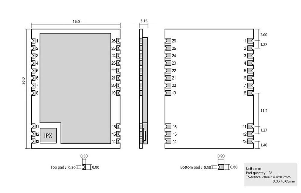
     3.1 E22-230/400/900T22S Mechanical Dimensions and Pin Definitions


          No          Name         Pin orientation                                       Pin Function
                                                          1.Module reset pin. Low-level trigger for reset, requiring a pull-down time
                                                          exceeding 100μs;
           1         RESET               Input
                                                          2.Users are strongly advised to connect to a microcontroller for reset and
                                                          recovery in unexpected situations.
           2          GND                   -             Module Ground
           3           NC                   -             Unused Pin (Leave Unconnected)
           4           NC                   -             Unused Pin (Leave Unconnected)
           5           NC                   -             Unused Pin (Leave Unconnected)
                                                          Empty pins (programming pins; if possible, bring them out for easier
           6           NC                   -
                                                          maintenance or firmware customization)
                                                          Empty pins (programming pins; if possible, bring them out for easier
           7           NC                   -
                                                          maintenance or firmware customization)
          8           GND                   -             Module Ground
          11          GND                   -             Module Ground
                                                          Antenna Interface (High-Frequency Signal Output, 50 Ohm Characteristic
          12           ANT               Output
                                                          Impedance)
          13          GND                   -             Module Ground
          14          GND                   -             Module Ground
          15          GND                   -             Module Ground

Copyright ©2012–2026,Chengdu Ebyte Electronic Technology Co.,Ltd.                                                                  8
Page 10
                                                                                          E22-T User Manual
          No          Name          Pin orientation                                       Pin Function
          16          GND                  -              Module Ground
          19          GND                  -              Module Ground
                                   Input (Very Weak       When combined with M1, determines the module's 4 operating modes
          20           M0
                                       Pull-Up)           (cannot be left floating)
                                   Input (Very Weak       When combined with M0, determines the module's 4 operating modes
          21           M1
                                       Pull-Up)           (cannot be left floating)
          22          RXD                Input            3.3V serial input, connected to external TXD output pin;
          23          TXD               Output            3.3V serial output, connected to external RXD output pin;
                                                          1. Indicates module operational status (may be left floating);
                                                          2. During normal operation, a low level on this pin indicates busy status,
                                                          while a high level indicates idle status;
                                                          3. It is not recommended to use this pin to drive external devices or pull it
          24          AUX                Output
                                                          low. Otherwise, if the AUX pin is continuously pulled low by an external
                                                          source during module power-up, the module may forcibly enter upgrade
                                                          mode and fail to operate normally. For detailed information, please refer to
                                                          Section 5.
          25          VCC                   -             Module Power Supply (Refer to the Electrical Parameters section)
          26          GND                   -             Module Ground


     3.2 E22-230/400/900T22D Mechanical Dimensions and Pin Definitions


Copyright ©2012–2026,Chengdu Ebyte Electronic Technology Co.,Ltd.                                                                    9
Page 11
                                                                                         E22-T User Manual
          No          Name         Pin orientation                                         Pin Function
                                  Input (Very Weak       When paired with M1, it determines the module's four operating modes
           1           M0
                                      Pull-Up)           (cannot be left floating; if not in use, it can be grounded).
                                  Input (Very Weak       When paired with M0, it determines the module's four operating modes
           2           M1
                                      Pull-Up)           (cannot be left floating; if not in use, it can be grounded).
           3          RXD               Input            TTL serial input, connected to external TXD output pin;
           4          TXD              Output            TTL serial output, connected to external RXD input pin;
                                                         1. Indicates module operational status (may be left floating);
                                                         2. During normal operation, a low level on this pin indicates busy status,
                                                         while a high level indicates idle status;
                                                         3. It is not recommended to use this pin to drive external devices or pull it
           5          AUX               Output
                                                         low. Otherwise, if the AUX pin is continuously pulled low by an external
                                                         source during module power-up, the module may forcibly enter upgrade
                                                         mode and fail to operate normally. For detailed information, refer to
                                                         Section 5.
           6          VCC           Power Supply         Module Power Supply (Refer to the Electrical Parameters section)
           7         GND            Power Supply         Module Ground
           8       Fixed hole            -                                                  Fixed hole
           9       Fixed hole            -                                                  Fixed hole
          10       Fixed hole            -                                                  Fixed hole


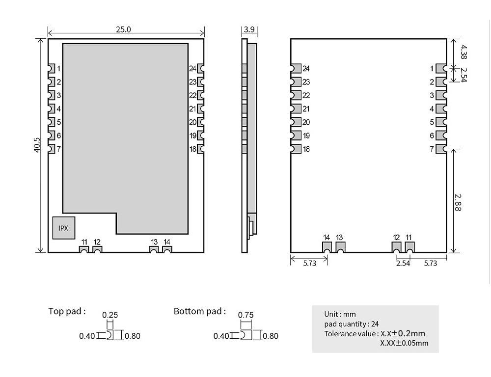
     3.3 E22-230/400/900T30S Mechanical Dimensions and Pin Definitions


Copyright ©2012–2026,Chengdu Ebyte Electronic Technology Co.,Ltd.                                                                    10
Page 12
                                                                                          E22-T User Manual
          No          Name         Pin orientation                                       Pin Function
           1          GND               Input            Module Ground
           2          VCC               Input            Module Power Supply (Refer to Electrical Parameters Section)
                                                         1. Indicates module operational status (may be left floating);
                                                         2. During normal operation, a low level on this pin indicates busy status,
                                                         while a high level indicates idle status;
                                                         3. It is not recommended to use this pin to drive external devices or pull it
           3          AUX               Output           low. Otherwise, if the AUX pin is continuously pulled low by an external
                                                         source during module power-up, the module may forcibly enter upgrade
                                                         mode and fail to operate normally. For detailed information, refer to
                                                         Section 5.
           4          TXD              Output            3.3V serial output, connected to the external RXD input pin;
           5          RXD               Input            3.3V serial input, connected to the external TXD output pin;
                                     Input (Very         In conjunction with M0, determines the module's four operating modes
           6           M1
                                    Weak Pull-Up)        (cannot be left floating).
                                     Input (Very         In conjunction with M1, determines the module's 4 operating modes
           7           M0
                                    Weak Pull-Up)        (cannot be left floating)
                                                         Antenna interface (high-frequency signal output, 50-ohm characteristic
          11          ANT               Output
                                                         impedance)
          12          GND                   -            Fixed location
          13          GND                   -            Fixed location
          14          GND                   -            Fixed location
                                                         Empty pin (programming pin; if possible, bring it out for easier
          18           NC
                                                         maintenance or firmware customization)
                                                         Empty pin (programming pin; if possible, bring it out for easier
          19           NC
                                                         maintenance or firmware customization)
          20           NC                                Empty pin (leave it open)
          21           NC                                Empty pin (leave it open)
                                                         1.Module reset pin. Low-level trigger for reset, requiring a pull-down time
                                                         exceeding 100μs;
          22         RESET               Input
                                                         2.Users are strongly advised to connect to a microcontroller for reset and
                                                         recovery in unexpected situations.
          23          GND                   -            Fixed
          24           NC                   -            Empty foot (please leave it suspended)


Copyright ©2012–2026,Chengdu Ebyte Electronic Technology Co.,Ltd.                                                                    11
Page 13
                                                                                        E22-T User Manual

     3.4 E22-230/400/900T30D Mechanical Dimensions and Pin Definitions


        No           Name          Pin orientation                                      Pin Function
                                    Input (Very         When used with M1, determines the module's four operating modes (cannot
         1             M0
                                   Weak Pull-Up)        be left floating; may be grounded if unused).
                                    Input (Very         When used with M0, determines the module's four operating modes (cannot
         2             M1
                                   Weak Pull-Up)        be left floating; may be grounded if unused).
         3            RXD              Input            TTL serial input, connected to external TXD output pin;
         4            TXD             Output            TTL serial output, connected to external RXD input pin;
                                                        1. Indicates module operational status (may be left floating);
                                                        2. During normal operation, a low level on this pin indicates busy status,
                                                        while a high level indicates idle status;
                                                        3. It is not recommended to use this pin to drive external devices or pull it
         5            AUX               Output
                                                        low. Otherwise, if the AUX pin is continuously pulled low by an external
                                                        source during module power-up, the module may forcibly enter upgrade
                                                        mode and fail to operate normally. For detailed information, please refer to
                                                        Section 5.
          6           VCC                Input          Module Power Supply (Refer to Electrical Parameters Section)
          7          GND                 Input          Module Ground Terminal
          8        Fixed hole              -            Mounting Hole
          9        Fixed hole              -            Mounting Hole
         10        Fixed hole              -            Mounting Hole
         11        Fixed hole              -            Mounting Hole


Copyright ©2012–2026,Chengdu Ebyte Electronic Technology Co.,Ltd.                                                                  12
Page 14
                                                                                      E22-T User Manual


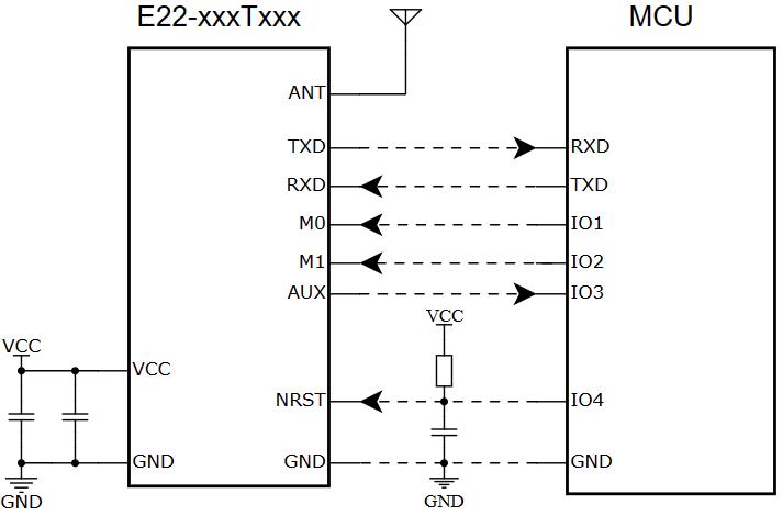
     4 Recommended Connection Diagram


        No                                                          Important Notes
                The module features a 3.3V serial port and I/O pins. Users with 5V microcontrollers must consider level
         1
                conversion.
         2      Strongly recommend connecting the RESET pin to prevent unexpected malfunctions.
                If adding an external switch to the module's VCC, account for leakage current from the external
         3
                microcontroller's serial port. Failure to do so may prevent module shutdown.
                Avoid using the AUX pin to drive external components (e.g., LEDs, relays). Continuous external pull-down
         4
                during power-on will cause malfunction.
                (Optional) For surface-mount modules, consider exposing the programming pins for future maintenance or
         5
                firmware customization.
                (Optional) Consider adding an auxiliary interface to the serial port for future maintenance (enabling online
         6
                upgrades via PC tools).


     5 Functions in detail

     • The M1 and M0 pins described in this section use 0 to represent a low level and 1 to represent a high level;
     • If using software switching mode, refer to the AT+MODE command in Chapter 7;


Copyright ©2012–2026,Chengdu Ebyte Electronic Technology Co.,Ltd.                                                              13
Page 15
                                                                                           E22-T User Manual

     5.1 Working Mode

     The module has four operating modes, set via pins M1 and M0, as detailed in the table below:
      Mode(0-3)           M1 M0                          Model Introduction                                    Remarks
            0
                                       Serial port enabled, wireless enabled, transparent        Can be remotely configured; see
       Transmission        0      0
                                       transmission                                              Section 5.1.3.2 for details.
          Mode
       1 WOR Mode          0      1    Can be defined as WOR sender and WOR receiver             Supports wake-on-air.
             2
                                       Users can access registers via the serial port to
       Configuration       1      0                                                              -
                                       control the module's operational state
          Mode
       3 Deep Sleep        1      1    Module enters sleep mode                                  -


     5.1.1 Transmission mode in use: Mode 0 (M1 and M0 pins set to 0,0)


     5.1.1.1 Quick Start Guide for Transparent Transfer

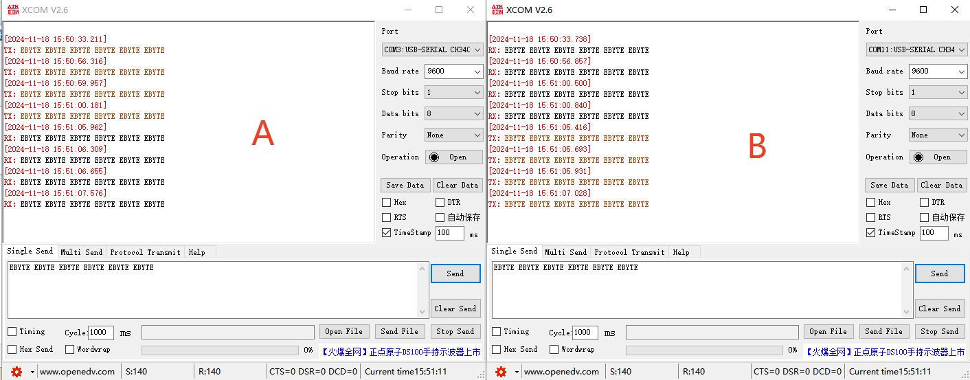
     What you see is what you get. Simply use Serial Port Assistant for mutual communication (all factory default parameters
     are identical, and transmission mode is transparent). An example scenario is as follows:


                                      Figure 1: Schematic of Bidirectional Transmission and Reception


     5.1.1.2 Quick Point-to-Point Transmission (Specify Destination Address and Channel)

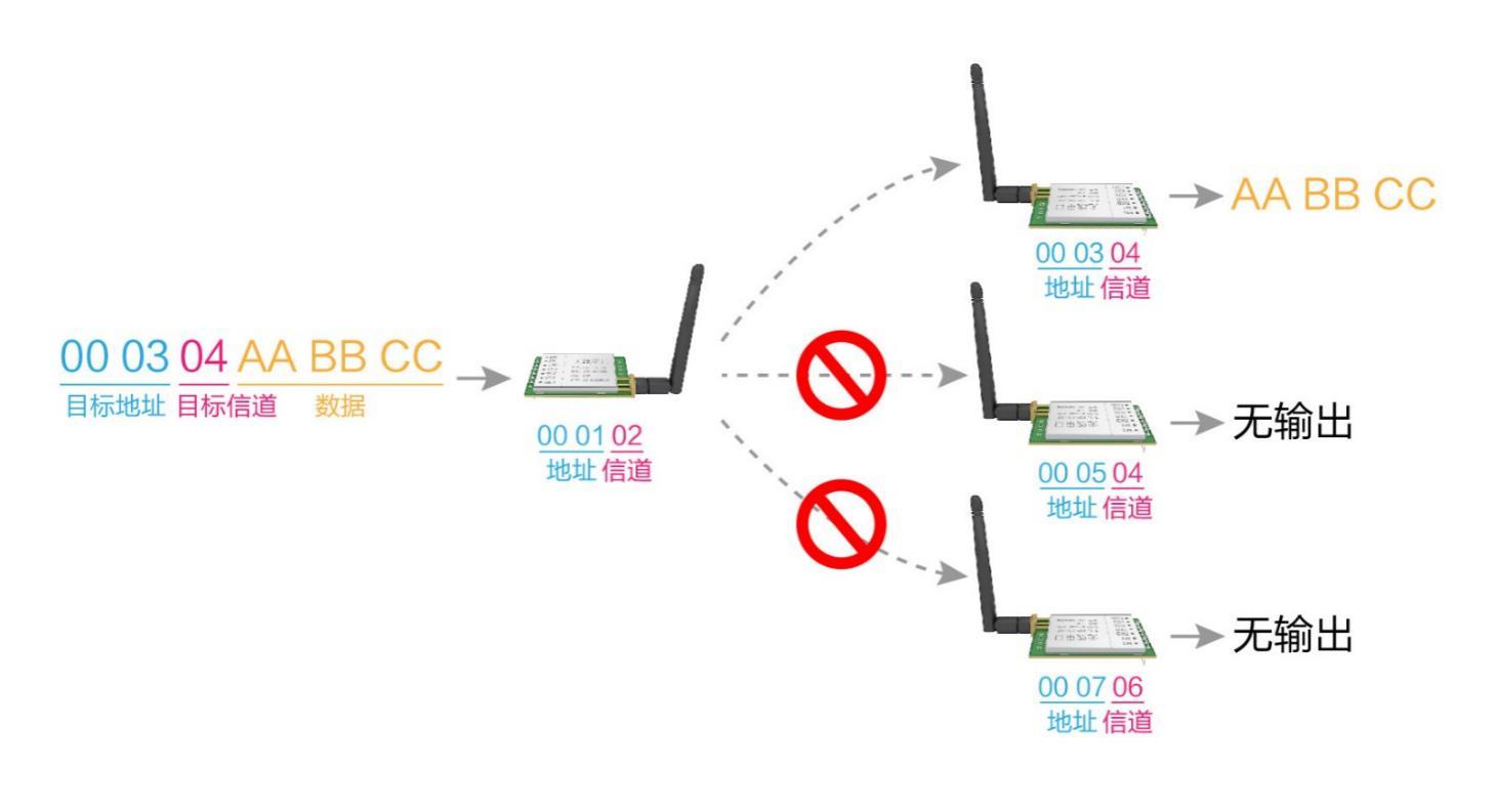
     Data transmission and reception follow a fixed format: destination address + destination channel + data. This effectively
     minimizes interference in certain scenarios.


Copyright ©2012–2026,Chengdu Ebyte Electronic Technology Co.,Ltd.                                                                  14
Page 16
                                                                                      E22-T User Manual


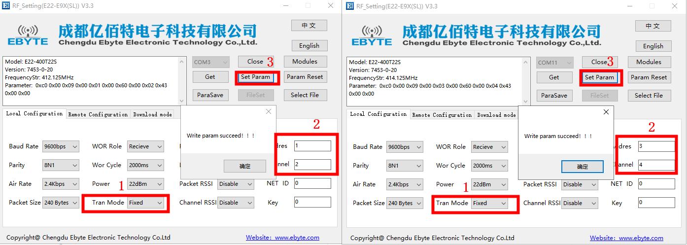
                                               Figure 2 Point-to-Point Transmission Schematic
     Operating Procedure:
     Step 1: Modify module parameters via the host computer:
     In configuration mode (set M1 and M0 pins to 1 and 0 respectively), modify the module address and channel. Change the
     transmission mode from transparent to fixed-point transmission. Finally, write the parameters to complete the modification.


                                                      Figure 3: Host Computer Interface
     Step 2: Switch the module operating mode to normal mode: Edit Module A parameters to 000304AABBCC and send to
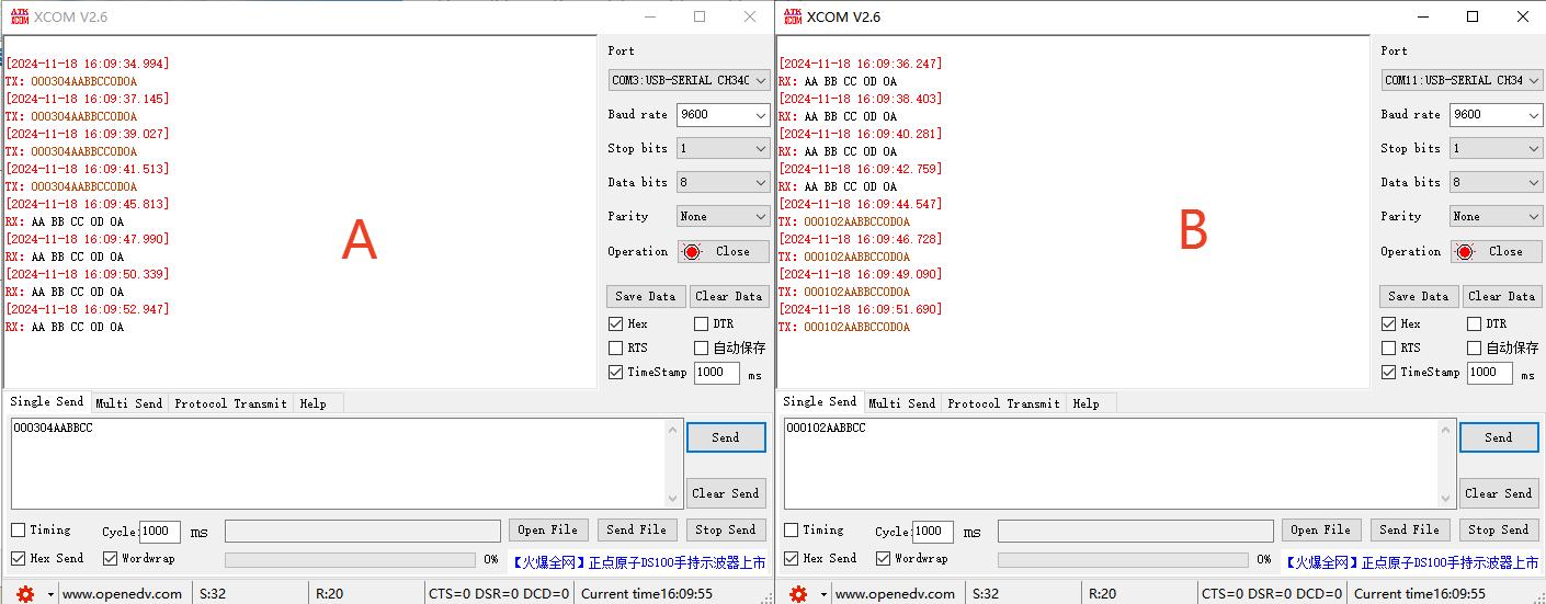
     Module B. Similarly, Module B sends data as 000102AABBCC. (Data transmission format in fixed-point mode:
     Destination address + Destination channel + Data)


Copyright ©2012–2026,Chengdu Ebyte Electronic Technology Co.,Ltd.                                                            15
Page 17
E22-T User Manual
Figure 4 Data Transmission Diagram
5.1.1.3 Quick Guide to Broadcasting
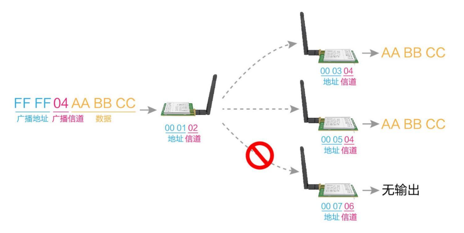
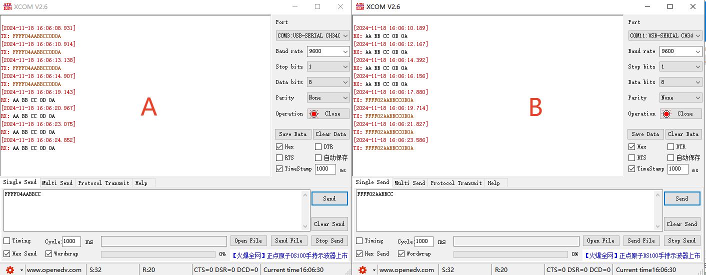
Set Module A's address to 0xFFFF and channel to 0x04. When Module A transmits (in the same mode, transparent or
fixed-point transmission), all receiving modules on channel 0x04 can receive the data, achieving broadcast
functionality.
Set Module A's address to 0xFFFF and channel to 0x04. When Module A operates as a receiver, it can receive all data
on channel 0x04, achieving monitoring functionality.
Figure 5 Point-to-Point Broadcast Transmission Diagram
Operating Procedure:
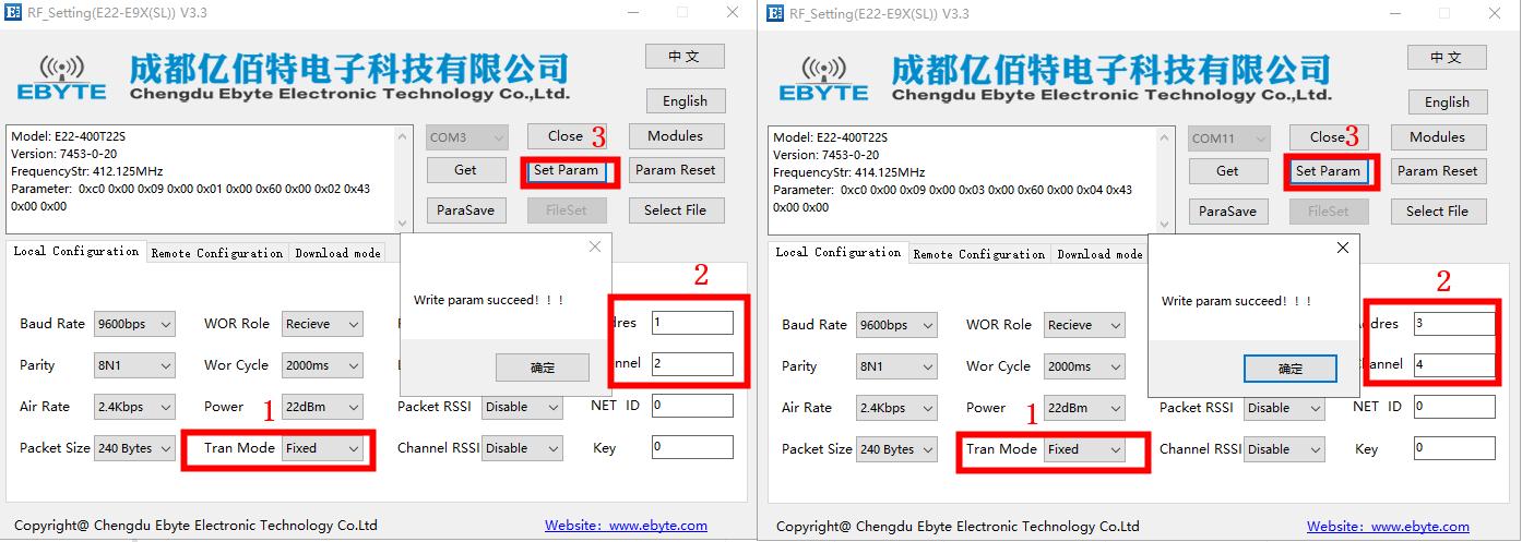
Step 1: Modify module parameters via the host computer:
In configuration mode (set M1 and M0 pins to 1 and 0), modify the module address and channel. Change the transmission
mode from transparent to fixed-point transmission. Finally, write the parameters to complete the modification.
Copyright ©2012–2026,Chengdu Ebyte Electronic Technology Co.,Ltd. 16
Page 18
                                                                                     E22-T User Manual


                                                 Figure 6: Host Computer Interface Diagram
     Step 2: Switch the module operating mode to normal mode: Edit Module A parameters to FFFF04AABBCC and transmit
     to Module B. Similarly, Module B transmits data as FFFF02AABBCC. (Data transmission format in point-to-point
     broadcast mode: Broadcast address + Target channel + Data).


                                                     Figure 7 Data Transmission Diagram


     5.1.2 Transmission mode in use: Mode 0 (M1 and M0 pins set to 0,0)


     5.1.2.1 Quick Start Guide for Transparent Transfer

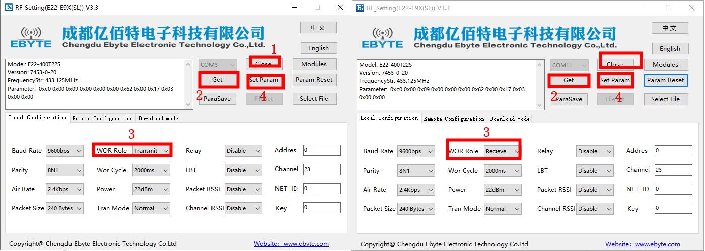
     Operating Procedure:
     Step 1: Modify module parameters via the host computer: In configuration mode (with M1 and M0 pins set to 1 and 0
     respectively), modify the module's WOR role and write the parameters to complete the modification.


Copyright ©2012–2026,Chengdu Ebyte Electronic Technology Co.,Ltd.                                                  17
Page 19
                                                                                     E22-T User Manual


                                                 Figure 8: Host Computer Interface Diagram
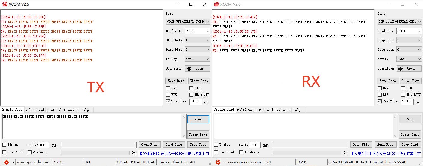
     Step 2: Switch the module operating mode to WOR mode (set M1 and M0 pins to 0,1): The WOR receiving module
     transmits data to the WOR transmitting module, but the WOR transmitting module cannot send data back to the transmitting
     module.


                                                     Figure 9 Data Transmission Diagram


     5.1.3 Configuration mode usage, Mode 2 (M1, M0 pins set to 1,0)


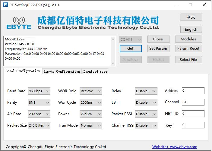
     5.1.3.1 Quick Start Guide for Configuration Tools

     The figure below shows the configuration interface for the host computer. Users can switch to command mode using M0
     or M1 to quickly configure and read parameters on the host computer.


Copyright ©2012–2026,Chengdu Ebyte Electronic Technology Co.,Ltd.                                                         18
Page 20
E22-T User Manual
Figure 10: Host Computer Interface Diagram
In the host computer configuration, module address, frequency channel, network ID, and key are all displayed in
decimal mode. For the valid parameter ranges, refer to the specific parameters for different product models in the
registers listed in Section 6.3.
When configuring relay mode via the host computer, users must pay special attention: since all parameters are
displayed in decimal mode on the host computer, module address and network ID must be converted to the appropriate
base when entered. For example, if the network ID entered at transmitter A is 02 and the network ID entered at receiver
B is 10, then when configuring the module address for repeater R, convert the hexadecimal value 0x020A to the
decimal value 522. This decimal value 522 should be entered as the module address for repeater R.
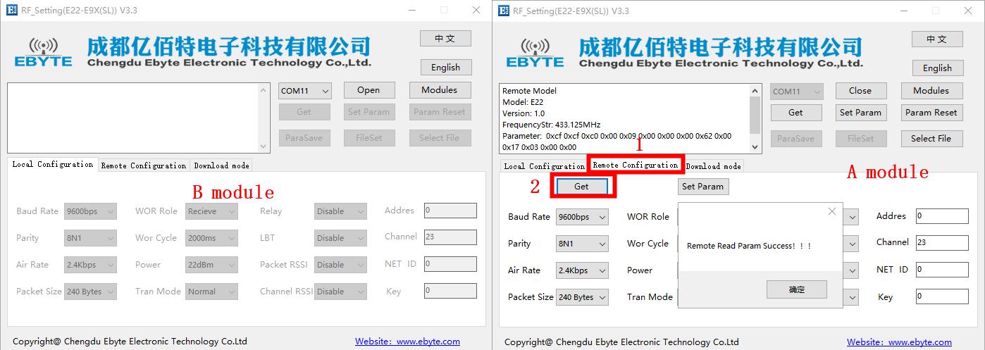
5.1.3.2 Quick Start Guide for Remote Configuration
Operating Procedure:
Step 1: Remotely read and modify module parameters via the host computer:
Modules A and B must have identical parameters to enable remote configuration.
Example shown in the right diagram:
Module A is in configuration mode, while Module B is in normal mode.
Simply open remote configuration on Module A via the host computer and read the parameters.
Copyright ©2012–2026,Chengdu Ebyte Electronic Technology Co.,Ltd. 19
Page 21
                                                                                     E22-T User Manual


                                                 Figure 11: Host Computer Interface Diagram


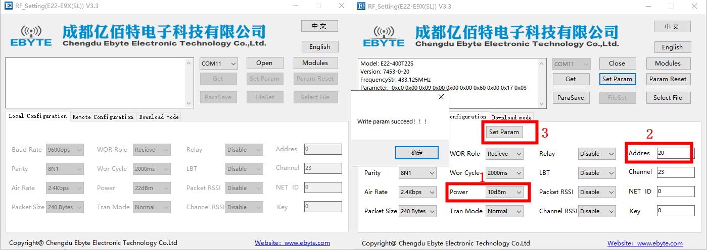
     Step 2: Modify parameters remotely and perform parameter writing.


                                  Figure 12: Host Computer Interface Diagram
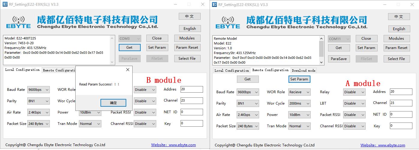
     Step 3: Switch Module B to configuration mode to view the modified parameters.


                                  Figure 13: Host Computer Interface Diagram


Copyright ©2012–2026,Chengdu Ebyte Electronic Technology Co.,Ltd.                                        20
Page 22
E22-T User Manual
5.1.4 Sleep Mode Usage, Mode 3 (M1, M0 pins set to 1,1)
To activate sleep mode, simply set the M1 and M0 pins to a high level. The module will then enter sleep mode with
minimal power consumption.
5.2 AUX Timing
5.2.1 Power-On Start Indicator
Tc = 25°C, VCC = 5 V
Para
mete Description Typical value Unit
rs
The entire startup process after powering on the module's VCC takes time
T1 16 ms
(entering operational mode, user-accessible state).
After the module's VCC power supply is applied, the AUX pin begins its initial
pull-down delay period. It does not immediately indicate a busy state (low level)
because the internal microcontroller also requires a certain startup time.
T2 Note: During the initial phase of T2, the AUX pin operates in internal pull-up input 5 ms
mode. If it detects an externally applied low signal lasting over 1 second (e.g., due
to an external pull-down resistor or shorting to GND), it will force an upgrade
state. This prevents normal wireless data transmission/reception and configuration
command processing. For further details, refer to the firmware upgrade section.
1 2 3 4 5 6 7 8 9 10 11 12 13
VCC
T1
AUX
T2
Figure 14 Power-Up Sequence Diagram
5.2.2 Serial Port Data Output Indicator
Conditions:Tc = 25°C, VCC = 5 V
Para
mete Description Typical value Unit
rs
After the module completes receiving air data packets, the AUX pin pulls low to
T1 3 ms
indicate to external users that the microcontroller is ready. It can also serve as a
Copyright ©2012–2026,Chengdu Ebyte Electronic Technology Co.,Ltd. 21
Page 23
                                                                                        E22-T User Manual

       Para
       mete                                             Description                                           Typical value      Unit
        rs

                 wake-up signal, suitable for certain low-power battery applications.

                 The module outputs the time interval between two consecutive packets of air
                 data.

                 Scenario 1: When the transmitter is transmitting data in an oversized packet loop
                 and the air rate significantly exceeds the receiver's serial port rate, the serial
                                                                                                                     0
                 output data from the receiver module will exhibit packet sticking (T2=0). The
                                                                                                                    or
                 length of a single serial output may exceed the user-defined packet size. This is
        T2                                                                                                          Tx            ms
                 suitable for applications where Modbus reads multiple registers from a slave
                                                                                                              (single packet
                 device and acknowledges responses.
                                                                                                                 airtime)
                 Scenario 2: When the sender is transmitting oversized packets in a loop, but both
                 the air interface rate and serial baud rate are slow (e.g., default air interface 2.4
                 Mbps, serial 9600 baud). In this case, air transmission is time-consuming, so the
                 receiver outputs packets at the packet interval.


             1       2        3          4          5    6          7   8        9    10          11     12       13        14   15
      AUX


      TXD                         0x01       0x02            n                             0x01               n

                         T1                                                 T2


                                         Figure 15 Serial Port Data Output Timing Diagram


     5.2.3 Wireless Transmission Indicator

     Tc = 25°C, VCC = 5 V
       Para
       mete                                             Description                                           Typical value      Unit
        rs

                 Internal buffer capacity of the module serial port (maximum single-transmission
                 data length). When the buffer contains data exceeding the user-defined packet
         n                                                                                                         1000          Byte
                 size (default 240 bytes), it will automatically segment the data for wireless
                 transmission processing.

                 AUX indicator delay time when the module receives serial data. The busy state
                 (pulled low) is only indicated after the module identifies and receives the first
        T1                                                                                                             1          ms
                 byte of the serial data packet. Therefore, the delay time is related to the serial
                 baud rate (default 9600 bps).

                 Module Cache Idle State AUX Indicator Delay (Pull-High) Time                                          3

                 Scenario 1: When the data length transmitted to the module is shorter than the                        Or
        T2       packet length (default 240 bytes), At this point, T2 represents the serial port                                  ms
                 reception frame break delay, with a default frame break time of 3 bytes                            Tx
                 (dependent on the serial port baud rate, default 9600). Once the frame break                 (Transmission
                 countdown ends, the AUX pin is immediately pulled high to indicate cache idle,                   time)

Copyright ©2012–2026,Chengdu Ebyte Electronic Technology Co.,Ltd.                                                                      22
Page 24
                                                                                         E22-T User Manual

       Para
       mete                                                  Description                                     Typical value    Unit
        rs

                  simultaneously triggering the air transmission process (under default conditions,
                  AUX does not indicate wireless transmission busy; refer to the AT+UAUX
                  command for additional settings).

                  Scenario 2: When the data length transmitted to the module exceeds the packet
                  size, T2 represents the total airtime consumption (dependent on air interface
                  rate). During serial reception, once the packet size is reached, the air transmission
                  process is triggered immediately (LoRa air transmission is relatively time-
                  consuming). Subsequent cycles involve multiple packet transmissions (based on
                  the incoming data length) until all data in the receive buffer is fully transmitted.
                  Only then is the AUX pin pulled high to indicate buffer availability.


              1         2          3          4          5         6         7       8    9         10       11      12      13
      RXD                   0x01       0x02       0x03                 n-1       n


      AUX

                             T1                                                                T2


                                          Figure 16 Wireless Transmission Timing Diagram


     5.2.4 Switch Mode

     When switching between all modes, the AUX will indicate a busy state for the duration specified in the table below:
            Original working mode                        Switch Mode                          T1 Switching Time (ms)
                                                     Transparent Mode                                    9~11
                   Sleep Mode
                                                             WOR Mode                                    9~11
                                                    Configuration Mode                                   9~11
                                                             Sleep Mode                                  9~11
               Transparent Mode
                                                             WOR Mode                                    9~11
                                                    Configuration Mode                                   9~11
                                                             Sleep Mode                                  9~11
              Configuration Mode
                                                     Transparent Mode                                    9~11
                                                             WOR Mode                                    9~11
                                                             Sleep Mode                                  9~11
                   WOR Mode                          Transparent Mode                                    9~11
                                                    Configuration Mode                                   9~11


Copyright ©2012–2026,Chengdu Ebyte Electronic Technology Co.,Ltd.                                                                 23
Page 25
E22-T User Manual
1 2 3 4 5 6 7 8 9 10 11 12 13
M0
M1
AUX
T1 T1 T1
Figure 17 Mode Switching Sequence Diagram
5.2.5 Important Notes
No AUX Notes
1 When the AUX output is low, it indicates the module is busy and will not perform mode detection.
2 If AUX remains high, mode switching will take effect immediately.
When transitioning from Mode 2 (Configuration Mode) to other modes or during reset, the module will reset
3
user parameters, during which the AUX output will be low.
5.3 Relay Networking Rules
Relay networking achieves expanded network coverage and enhanced communication reliability by forwarding data
between source and destination nodes via relay nodes.
No Relay Mode Description
After configuring relay mode in the configuration pattern, switching to normal mode enables the relay to
1
operate, facilitating bidirectional data forwarding between two NETIDs.
In relay mode, ADDH and ADDL no longer function as module addresses but correspond to NETID
2
forwarding pairs. If data is received from one network, it is forwarded to the other network.
3 In relay mode, the relay module cannot send or receive data and cannot perform low-power operations.
4 The relay's own network ID becomes invalid.
Using two or more relays with identical or swapped ADDH and ADDL addresses is not recommended, as it
5
may cause circular forwarding between relays.
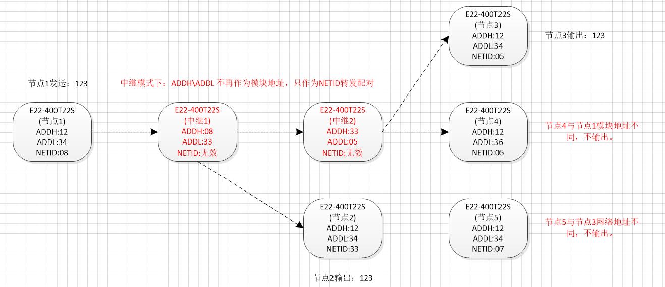
As shown in the example diagram below:
Tier 1 Relay
Node 1 has a NETID of 08. Node 2 has a NETID of 33.
Relay 1 has ADDH and ADDL values of 08 and 33, respectively.
Therefore, signals sent by Node 1 (08) can be forwarded to Node 2 (33).
Since Node 1 and Node 2 share the same address, data sent by Node 1 can be received by Node 2.
Secondary Relay
Relay 2's ADDH and ADDL are 33 and 05, respectively.
Copyright ©2012–2026,Chengdu Ebyte Electronic Technology Co.,Ltd. 24
Page 26
E22-T User Manual
Therefore, Relay 2 can forward Relay 1's data to network NETID: 05.
Consequently, Node 3 and Node 4 can receive Node 1's data. Node 4 outputs data normally, while Node 3 does
not output data because its address differs from Node 1's.
Bidirectional Relay
As configured in the diagram: Data sent by Node 1 can be received by Nodes 2 and 4. Data sent by Nodes 2 and 4
can also be received by Node 1.
Figure 18: Relay Network Diagram
5.4 Serial Port Firmware Upgrade
① If customers require firmware upgrades, they must obtain the corresponding upgrade package through their sales
channel contact. Use the host computer provided by Yibait to perform the firmware upgrade. Under normal circumstances,
users do not need to upgrade the firmware. Do not use the “AT+IAP” command.
② The pins required for the upgrade must be brought out (M1, M0, AUX, TXD, RXD, VCC, GND). Then, send the
“AT+IAP” command in configuration mode to enter upgrade mode.
③ After entering upgrade mode, the baud rate will automatically switch to 115200 until it exits automatically. Log output
will be displayed during this process.
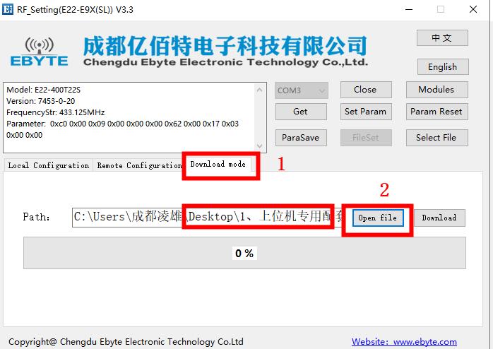
5.4.1 Quick Guide to Host Computer Upgrade
Step 1: Enter configuration mode by changing M0 and M1 (Note: Baud rate is 9600 in configuration mode). Open the
configuration host computer and select the Firmware Upgrade tab.
Step 2: Click Read Parameters to view module information in the left window of the host computer.
Step 3: Open File (select the firmware.bin file) > Click Start Download.
Step 4: Click Start Download to begin the firmware upgrade. A success message will appear upon completion.
Step 5: After the firmware upgrade finishes, reopen the serial port and verify the parameters by clicking Read Parameters.
Copyright ©2012–2026,Chengdu Ebyte Electronic Technology Co.,Ltd. 25
Page 27
                                                                                     E22-T User Manual


                 Figure 18: Host Computer Interface Diagram


     6 Register Read/Write Control


     6.1 HEX Instruction Format

     In configuration mode (Mode 2: M1=1, M0=0), the supported command list is as follows (when setting, the serial port only
     supports 9600 baud, 8N1 format):
                  Command
       No                                                             Detailed Description
                   Format
                                     Command: C0 + Start Address + Length + Parameters
                                     Response: C1 + Start Address + Length + Parameters

                                     Example 1: Configure channel to 0x09
                                     Command Start Address Length Parameters
                                     Send: C0 05 01 09
        1       Set the register
                                     Return: C1 05 01 09

                                     Example 2: Simultaneously configure module address (0x1234), network address (0x00),
                                     serial port (9600 8N1), baud rate (2.4K)
                                     Send: C0 00 04 12 34 00 61
                                     Return: C1 00 04 12 34 00 61
                                     Command: C1 + Start Address + Length
                                     Response: C1 + Start Address + Length + Parameters
        2        Read register
                                     Example 1: Read Channel
                                     Command Start Address Length        Parameter

Copyright ©2012–2026,Chengdu Ebyte Electronic Technology Co.,Ltd.                                                           26
Page 28
                                                                                         E22-T User Manual
                   Command
       No                                                                   Detailed Description
                    Format
                                     Send: C1          05           01
                                     Return: C1         05           01       09

                                     Example 2: Simultaneously Read Module Address, Network Address, Serial Port, Airspeed
                                     Send: C1 00 04
                                     Return: C1 00 04 12 34 00 62/63
                                     Command: C2 + Start Address + Length + Parameters
                                     Response: C1 + Start Address + Length + Parameters

                                     Example 1: Configure channel to 0x09
                                     Command      Start Address      Length          Parameters
                  Set temporary      Send: C2     05          01       09
        3
                    registers        Return: C1     05          01       09

                                     Example 2: Simultaneously configure module address (0x1234), network address (0x00),
                                     serial port (9600 8N1), baud rate (2.4K)
                                     Send: C2 00 04 12 34 00 61
                                     Return: C1 00 04 12 34 00 62/63
                                     Command: CF CF + Standard Command
                                     Response: CF CF + Standard Response

                                     Example 1: Wireless configuration channel set to 0x09
                                     Wireless Command Header       Command Start Address            Length      Parameters
                    Wireless         Send: CF CF           C0        05          01      09
        4
                  Configuration      Return: CF CF         C1        05         01       09

                                     Example 2: Simultaneously configure module address (0x1234), network address (0x00),
                                     serial port (9600 8N1), baud rate (2.4K)
                                     Send: CF CF C0 00 04 12 34 00 62/63
                                     Return: CF CF C1 00 04 12 34 00 62/63
                                     Format Error Response
        5         Format error
                                     FF FF FF


     6.2 Register Function Reference Table

                                                                                Bit
        Address        Name
                                      bit 7          bit6           bit5         bit4         bit3           bit2    bit1    bit0
            00h        ADDH                                            Mailing Address [15:8]
            01h        ADDL                                            Mailing Address [7:0]
            02h        NETID                                           Network Address [7:0]
            03h        REG0                Serial Port Baud Rate [2:0]           Serial Port Parity        Wireless Transmission
                                                                                    Type [1:0]                    Rate [2:0]
            04h        REG1            Serial Port Packet     Environmental reserve         reserve       Soft-cut      Wireless
                                         Length [1:0]              RSSI                                    mode      Transmission
                                                                                                                      Power [1:0]
            05h        REG2                                                Channel Control [7:0]
            06h        REG3           Data      Transmission        Relay Enable    Listen       Air         Air Wake Cycle [2:0]
                                      RSSI        Method                             first,   Wake-Up
                                                                                     then
                                                                                    speak.
            07h      CRYPT_H                                        Wireless Data Encryption Key [15:8]
            08h      CRYPT_L                                        Wireless Data Encryption Key [7:0]

Copyright ©2012–2026,Chengdu Ebyte Electronic Technology Co.,Ltd.                                                                   27
Page 29
                                                                                            E22-T User Manual
           09h         WD_H           Air-to-Air Wake-Up Recipient, Window Time for Acknowledgment (Transmission) After
                                                                      Data Receipt [15:8]
           0Ah         WD_L           Air-to-Air Wake-Up Recipient, Window Time for Acknowledgment (Transmission) After
                                                                       Data Receipt [7:0]
     Note: For reference on register software structure design, consult the E22-xxxTBL-SC series sample code (available in the
     relevant download section of this page). See e22_demo.h for details.


     6.3 Register Specificationsj

             Read
              and
      No               Name                           Description                                                Note
             Writ
              e
             Read                                                                          1. High byte and low byte of the module
      00                ADD
             and                 ADDH(Default 0)                                           address;
      H                  H
             Write                                                                         2. When the module address equals FFFF, it
             Read                                                                          can serve as a broadcast and listening address,
      01                ADD
             and                 ADDL(Default 0)                                           meaning: the module will not perform address
      H                  L
             Write                                                                         filtering at this time.
                                                                                           1. Network address, used to distinguish
             Read
      02               NETI                                                                networks;
             and                 NETID(Default 0)
      H                 D                                                                  2. Must be set to the same value for mutual
             Write
                                                                                           communication.
                                  7    6    5     UART Serial Port Speed (bps)             1. Two modules communicating with each
                                  0    0    0     Serial port baud rate: 1200              other may have different serial port baud
                                  0    0    1     Serial port baud rate: 2400              rates and parity settings;
                                  0    1    0     Serial port baud rate: 4800              2. When transmitting large data packets
                                                  Serial   port     baud    rate:   9600   consecutively, users should consider potential
                                  0    1    1
                                                  (Default)                                data blocking or even loss caused by differing
                                  1    0    0     Serial port baud rate: 19200             baud rates;
                                  1    0    1     Serial port baud rate: 38400             3. It is generally recommended that both
                                  1    1    0     Serial port baud rate: 57600             communicating parties use the same baud
                                  1    1    1     Serial port baud rate: 115200            rate.
             Read                 4    3    Serial Port Parity Bit
      03
              and                 0    0    8N1(Default)
       H               REG0                                                                The serial port modes of the communicating
             Write                0    1    8O1
                                                                                           parties may differ;
                                  1    0    8E1
                                  1    1    8N1(equivalent 00)
                                                     Wireless Air Interface Rate
                                                                                           1. E22-400Txxx①:E22-400T22D、E22-
                                                                  (bps)                    400T22S、E22-400T30D、E22-400T30S
                                                       E22-                                2. E22-900Txxx②:E22-900T22D、E22-
                                  2    1    0
                                                    400Txxx①                 E22-          900T22S、E22-900T30D、E22-900T30S
                                                       E22-                230Txxx③        3. E22-230Txxx③:E22-230T22D、E22-
                                                                                           230T22S、E22-230T30D、E22-230T30S
                                                    900Txxx②
                                  0    0    0      Air Rate 2.4k       Air Speed 2.4k      Note: Both communication parties must share
                                  0    0    1      Air Rate 2.4k       Air Speed 2.4k      the same air interface rate; a higher air

Copyright ©2012–2026,Chengdu Ebyte Electronic Technology Co.,Ltd.                                                                      28
Page 30
E22-T User Manual
Air Rate 2.4k interface rate results in lower latency but
0 1 0 Air Speed 2.4k shorter transmission distance.
(Default)
Air Speed 2.4k
0 1 1 Air Rate 4.8k
(Default)
1 0 0 Air Rate 9.6k Air Speed 4.8k
1 0 1 Air Rate 19.2k Air Speed 9.6k
Air Speed
1 1 0 Air Rate 38.4k
15.6k
Air Speed
1 1 1 Air Rate 62.5k
15.6k
7 6 Subcontract Settings Note:
0 0 240 bytes (default) 1. If the user sends data shorter than the
0 1 128 bytes packet length, the receiving serial port will
1 0 64 bytes output it as a continuous stream without
interruption.
2. If the user sends data longer than the
1 1 32 bytes
packet length, the receiving serial port will
output it in separate packets.
5 RSSI Environmental Noise Enable 1. After enabling, the C0 C1 C2 C3
command can be sent in transmission mode
or WOR send mode to read the register;
0 Disabled (default) 2. Register 0x00: Current environmental
noise RSSI;
3. Register 0x01: RSSI at the time of last
data reception (current environmental
noise: dBm = -(256 - RSSI));
4. Command format: C0 C1 C2 C3 + start
address + read length;
04 Read 1 Enable
Return: C1 + address + read length +
H and REG1 valid read value;
Example: Send C0 C1 C2 C3 00 01
Write
Return: C1 00 01 RSSI (addresses must
start from 00)
4 3 reserve
2 Software Mode Switching 1. If using our company's host computer
0 Disabled (Default) configuration parameters, this pin will be
automatically disabled. To avoid using the
M0 and M1 pins for switching operating
modes, you can enable this feature and use
specific serial port commands to switch
modes.
1 Enable 2. Format: C0 C1 C2 C3 02 + Operating
Mode:
Send C0 C1 C2 C3 02 00 to switch to
transparent mode;
Send C0 C1 C2 C3 02 01 to switch to WOR
mode;
Copyright ©2012–2026,Chengdu Ebyte Electronic Technology Co.,Ltd. 29
Page 31
E22-T User Manual
Send C0 C1 C2 C3 02 02 to switch to
configuration mode;
Send C0 C1 C2 C3 02 03 to switch to
sleep mode;
Return: C1 C2 C3 02 + operating mode;
Note: After enabling this feature,
configuration mode still only supports 9600
baud rate.
Transmit Power
1 0 Suitable for Suitable for
30dBm modules 22dBm modules 1. Power and current exhibit a nonlinear
30dBm 22dBm relationship; power supply efficiency peaks at
0 0 maximum power output.
(Default) (Default)
2. Current does not decrease proportionally
0 1 27dBm 17dBm with reduced power.
1 0 24dBm 14dBm
1 1 21dBm 10dBm
Channel Control (CH)
0-64 represents a total of 65 channels (applicable 1.230 band actual frequency = 220.125 + CH
× 0.25 MHz
Read to the 230 band) 2.400 band actual frequency = 410.125 + CH
05
and REG2 0-83 represents a total of 84 channels (applicable × 1 MHz
H 3.900 band actual frequency = 850.125 + CH
Write to the 400 band)
× 1 MHz
0-80 represents a total of 81 channels (applicable
to the 900 band))
7 Enable RSSI bytes (packet RSSI) 1. After activation, when the module receives
wireless data, it outputs via the serial port
0 Disabled (default) TXD followed by an RSSI strength byte.
2. The current packet RSSI is: dBm = -(256 -
1 Enable RSSI)
6 Transmission Mode During fixed-point transmission, the module
identifies the first three bytes of serial data
0 Transparent Transmission (Default) as: address high byte + address low byte +
1 Point-to-Point Transmission channel, and uses this as the wireless
transmission target.
5 Relay Function 1. When relay functionality is enabled, if the
destination address is not the module itself, the
0 Disable Relay Function (Default) module will initiate a single forwarding
Read
06 operation.
and REG3 2. To prevent data backhaul, it is
H
Write 1 Enable Relay Function recommended to use this feature in
conjunction with fixed-point mode; that is, the
destination address must differ from the
source address.
4 LBT Enable 1. When enabled, wireless data transmission
will perform listening before transmission,
0 Disable (Default) which can help avoid interference to some
extent but may cause data delays.
1 Enable 2. The maximum LBT dwell time is 2
seconds; transmission will be forced once this
duration is reached.
3 WOR Mode Transmit/Receive Control Applicable only to Mode 1;
0 WOR Receiver (Default) 1. In WOR receive mode, the module can
Copyright ©2012–2026,Chengdu Ebyte Electronic Technology Co.,Ltd. 30
Page 32
                                                                                      E22-T User Manual
                                      Operates in WOR listening mode with a          modify the wake-up delay time, with the
                                                                                     default time set to 0;
                                      listening cycle as described below (WOR
                                                                                     2. The receiver must send the command C0 09
                                      cycle), enabling significant power savings.    02 03 E8 in configuration mode (C0 is the
                                                                                     write command, 09 is the starting address of
                                      WOR Transmitter                                the register, 02 is the length, 03 E8 is the set
                                      The module's transceiver is activated, and a   delay time, with a maximum of FFFF
                                  1                                                  corresponding to 65535ms; setting it to 0
                                      wake-up code of a specified duration is        disables the wake-up delay).
                                      inserted during data transmission.             3. Data can be transmitted within the delay
                                                                                     period.
                                  2    1    0    WOR Cycle
                                  0    0    0    500ms
                                                                                     Applicable only to Mode 1;
                                  0    0    1    1000ms                              1. Cycle T = (1 + WOR) × 500 ms, maximum
                                  0    1    0    1500ms                              4000 ms, minimum 500 ms;
                                                                                     2. Longer WOR monitoring interval cycles
                                  0    1    1    2000ms(Default)
                                                                                     result in lower average power consumption
                                  1    0    0    2500ms                              but increased data latency;
                                  1    0    1    3000ms                              3.Transmitter and receiver must be
                                                                                     synchronized (critical).
                                  1    1    0    3500ms
                                  1    1    1    4000ms
      07               CRYP                                                          1.Write only; reads return 0;
             Write               Key High Byte (Default 0)                           2.Used for encryption to prevent interception
       H                T_H
                                                                                     of wireless data by similar modules;
      08               CRYP                                                          3.Internally, the module will use these two
             Write               Key Low Byte (Default 0)                            bytes as computational factors to transform
       H                T_L
                                                                                     and encrypt wireless signals.
      80
                                                                                     Product Information 7 bytes
       H
                                                                                     Note: Refer to Section 7.1 for the
      ~      Read       PID      Product Information 7 bytes
                                                                                     AT+DEVTYPE=? query command, which is
      86
                                                                                     more convenient.
       H


     6.4 Register Parameter Factory Default Values


                               Factory default parameter values for 230MHz module: C0 00 09 00 00 00 63 00 28 03 00 00
            Model              Factory default parameter values for 400MHz module: C0 00 09 00 00 00 62 00 17 03 00 00
                               Factory default parameter values for 900MHz module:: C0 00 09 00 00 00 62 00 12 03 00 00
                                                                                              Serial Port     Transmit
             SKU                Frequency       Address Channel        Air Rate  Baud rate
                                                                                                Format         Power
        E22-230T22S
                               230.125MHz           0x0000          0x28   2.4kbps         9600           8N1             22dbm
        E22-230T22D
        E22-230T30S
                               230.125MHz           0x0000          0x28   2.4kbps         9600           8N1             30dbm
        E22-230T30D
        E22-400T22S
                               433.125MHz           0x0000          0x17   2.4kbps         9600           8N1             22dbm
        E22-400T22D

Copyright ©2012–2026,Chengdu Ebyte Electronic Technology Co.,Ltd.                                                                 31
Page 33
E22-T User Manual
E22-400T30S
433.125MHz 0x0000 0x17 2.4kbps 9600 8N1 30dbm
E22-400T30D
E22-900T22S
868.125MHz 0x0000 0x12 2.4kbps 9600 8N1 22dbm
E22-900T22D
E22-900T30S
868.125MHz 0x0000 0x12 2.4kbps 9600 8N1 30dbm
E22-900T30D
7 AT Commands
Parameter configuration or queries using AT commands must be performed in configuration mode (configuration
mode serial port is fixed at 9600 8N1);
For software version (7453-0-20) and earlier, no carriage return/line feed is required at the end of user-entered AT
commands;
Starting with software version (7453-0-21), the system automatically recognizes the carriage return/line feed at the
end of user AT commands and will still recognize them even without the return/feed;
If AT command recognition or execution encounters an error, the response “=ERR” will be returned;
Input parameters exceeding the specified range will be restricted. Do not allow parameters to exceed the range to
avoid unexpected situations.
7.1 General Command
7.1.1 AT+RESET Software Reset
Command
AT+RESET
Format
Execution Send: AT+RESET
Example Response: =OK
Software versions (7453-0-20) and earlier will not respond with “=OK”.
Feature Software versions (7453-0-21) and later will respond with “=OK”.
Description The actual reset process will only begin after the “=OK” response. Users should wait approximately
30ms before proceeding with the next operation.
7.1.2 AT+DEFAULT Restore factory settings
Command
AT+DEFAULT
Format
Execution Send: AT+DEFAULT
Example Response: =OK
Feature After acknowledging (=OK), the system will perform parameter restoration and initiate a restart process.
Description Please wait approximately 30 milliseconds before proceeding with the next operation.
Copyright ©2012–2026,Chengdu Ebyte Electronic Technology Co.,Ltd. 32
Page 34
E22-T User Manual
7.1.3 AT+DEVTYPE Query product model
Command AT+DEVTYPE=?
Format
Execution Send: AT+DEVTYPE=?
Example Response: DEVTYPE=E22-400T30S
Product Series: E22
Feature
Operating Frequency Bands: 400 (170/230/400/900)
Description
Maximum Power: 30 (22/30/33)
7.1.4 AT+FWCODE Query Software Version
Command AT+FWCODE=?
Format
Execution Send: AT+FWCODE=?
Example Response: FWCODE=7453-0-23
Major Version: 7453
Feature
Branch Number: 0
Description
Minor Version: 23 (increments starting from 10)
7.1.5The AT+SWITCH software switching mode is enabled
Command AT+SWITCH=<on_off>
Format
Configuration Send: AT+SWITCH=0
Examples Response: =OK
Query Send: AT+SWITCH=?
Examples Response: AT+SWITCH=0
<on_off>: Switch
Parameter
0 Off (default)
Descriptions
1 On
Factory default is disabled. Use the M0M1 pin to switch operating modes (hard switch).
When enabled, the M0M1 pin remains functional. The last triggered switch (hard or soft) takes
precedence.
After enabling, restart the system for it to take effect.
When enabled, AT+MODE can be used to specify the operating mode (soft switch), and each soft
Feature
switch immediately saves the operating mode number
Descriptions
When enabled, for software versions (7453-0-20) and earlier, the initial operating mode after power-
off restart is determined by the M0/M1 hardware mode
When enabled, for software versions (7453-0-21) and later, the last saved soft-switch mode number
becomes the initial operating mode after power-off reset.
When disabled, the M0/M1 hardware mode becomes the initial operating mode after power-off reset.
7.1.6 AT+MODE Software Mode Switching
Command AT+MODE=<mode>
Format
Configuration Send: AT+MODE=0
Example Response: AT+MODE=0
Copyright ©2012–2026,Chengdu Ebyte Electronic Technology Co.,Ltd. 33
Page 35
E22-T User Manual
Query Send: AT+MODE=?
Example Response: AT+MODE=0
<mode>: Operating Mode Number
0 Transmission Mode
Parameter
1 Wake-on-Radio Mode (WOR)
Description
2 Configuration Mode
3 Sleep Mode
Must be enabled via AT+SWITCH before use
Operates in any working mode
Feature Actual mode switching begins only after acknowledgment (=OK); users should wait approximately
Description 15ms before proceeding
Refer to AT+SWITCH feature documentation
See Chapter 5 for detailed switching time specifications
7.1.7 AT+UAUX Wireless AUX Indicator Enable
Command AT+UAUX=<on_off>
Format
Configuration Send: AT+UAUX=0
Example Response: =OK
Query Send: AT+UAUX=?
Example Response: AT+UAUX=0
<on_off>: Switch
Parameter
0 Off (default)
Description
1 On
Software version (7453-0-20) and earlier do not support this command. By default, AUX indicates
the wireless transmission process (pulls low during transmission). For upgrades, please contact
Yibait staff.
Feature
Software version (7453-0-21) and later versions are disabled by default. AUX does not indicate the
Description
wireless transmission process (enabling faster packet transmission for some users). Enable this
feature if compatibility with previous AUX timing is required.
For detailed AUX timing output specifications, refer to Chapter 5.
7.1.8 AT+ADDR Communication Address (Matching Filter)
Command AT+ADDR=<address>
Format
Configuration Send: AT+ADDR=0
Example Response: =OK
Query Send: AT+ADDR=?
Example Response: AT+ADDR=0
Parameter <address>: Postal Address 0 - 65535
Description
Default address 0
The address is not an RF characteristic but merely an identifier carried within the packet, assisting
Feature the receiving software logic in determining whether to perform matching and filtering.
Description Broadcast address 65535. As a receiver, it can receive data sent from any address on the same channel
(unfiltered). As a sender, the transmitted packet carries the broadcast address, so the recipient will
not filter it either (broadcast data).
Copyright ©2012–2026,Chengdu Ebyte Electronic Technology Co.,Ltd. 34
Page 36
E22-T User Manual
7.1.9 AT+NETID Communication Network Code (Matching Filter)
Command AT+NETID=<net>
Format
Configuration Send: AT+NETID=0
Example Response: =OK
Query Send: AT+NETID=?
Example Response: AT+NETID=0
Parameter <net>: Network code 0 - 255
Description
Default network 0
Network codes are not RF characteristics but merely identifiers carried within packets, assisting
Feature
receiving-end software logic in determining whether to relay forwarding or filtering.
Description
Network code filtering has lower priority than broadcast addresses. Even with differing network
codes, broadcast data can still be received.
7.1.10 AT+CHANNEL Communication Channel (Carrier Frequency)
Command AT+CHANNEL=<ch>
Format
Configuration Send: AT+CHANNEL=0
Example Response: =OK
Query Send: AT+CHANNEL=?
Example Response: AT+CHANNEL=0
Communication Channel Communication Channels 0 - 80 Communication Channels 0 - 63
0 - 83 E22-900T22D, E22-900T22S, E22-230T22D, E22-230T22S,
Parameter
E22-400T22D, E22- E22-900T30D, E22-900T30S E22-230T30D, E22-230T30S
Description
400T22S, E22-400T30D,
E22-400T30S
Channel ranges differ across frequency bands; please note the distinctions.
For the 230 MHz band, the actual carrier frequency corresponds to:= 220.125 MHz + channel * 0.25
MHz
Feature
For the 400 MHz band, the actual carrier frequency corresponds to:= 410.125 MHz + channel
Description
frequency × 1 MHz
For the 900 MHz band, the actual carrier frequency corresponds to:= 850.125 MHz + channel
frequency × 1 MHz
7.1.11 AT+KEY Communication Password (Data Encryption)
Command AT+KEY=<key>
Format
Configuration Send: AT+KEY=0
Example Response: =OK
Parameter <key>: Encryption/decryption password 0 - 65535
Description
Default 0
Feature Unable to query (cannot read password)
Description Modules with mismatched passwords cannot communicate (unable to decode correct data packets,
fail verification checks and are discarded)
Copyright ©2012–2026,Chengdu Ebyte Electronic Technology Co.,Ltd. 35
Page 37
E22-T User Manual
7.1.12 AT+UART Serial Port Baud Rate and Parity
Command AT+UART=<baud>,<parity>
Format
Configuration Send: AT+UART=3,0
Example Response: =OK
Query Send: AT+UART=?
Example Response: AT+UART=3,0
<baud>: Serial port baud rate
0 1200bps
1 2400bps
2 4800bps
3 9600bps (default)
4 19200bps
Parameter 5 38400bps
Description 6 57600bps
7 115200bps
<parity>: Serial port parity type
0 None (default)
1 Odd parity
2 Even parity
Feature In configuration mode (M0M1 Mode 2), force fixed 9600 8N1
Description Takes effect after switching operating modes
7.1.13 AT+PACKET Serial Packet Length
Command AT+PACKET=<len>
Format
Configuration Send: AT+PACKET=0
Example Response: =OK
Query Send: AT+PACKET=?
Example Response: AT+PACKET=0
<len>: Serial data packet length
0 240 bytes (default)
Parameter
1 128 bytes
Description
2 64 bytes
3 32 bytes
During serial port reception, if user-transmitted data falls short of the set length, it is processed as a
timeout frame break and repackaged for wireless transmission.
During serial port reception, when user-transmitted data reaches the set length, it is immediately
Feature
packaged for wireless transmission.
Description
Data exceeding the set length continues to accumulate in the serial port buffer. After wireless
transmission completes, it is resplit according to the set length and sent in single packets
cyclically.
7.1.14 AT+URXT Serial Port Frame Disconnection Condition
Command AT+URXT=<byte>
Format
Configuration Send: AT+URXT=3
Copyright ©2012–2026,Chengdu Ebyte Electronic Technology Co.,Ltd. 36
Page 38
E22-T User Manual
Example Response: =OK
Query Send: AT+URXT=?
Example Response: AT+URXT=3
Parameter <byte>: Byte time 1 - 255
Description
Default serial port frame break processing uses a 3-byte timeout.
Timeout duration varies by baud rate (per-byte time). At 9600 baud, approximately 1 millisecond
per byte; at 115200 baud, approximately 100 microseconds per byte.
Feature
Some customers experience discontinuous data transmission from external microcontroller serial
Description
ports to the module (e.g., due to RTOS task interruptions). When data exceeds the module's
configured byte time window, it is treated as a frame break and manifests as packet fragmentation
at the receiving end.
7.1.15 AT+RATE Wireless Transmission Rate
Command AT+RATE=<rate>
Format
Configuration Send: AT+RATE=2
Example Response: =OK
Query Send: AT+RATE=?
Example Response: AT+RATE=2
Air Speed <rate>: Air Data Rate
E22-400T22S, E22-400T22D, E22-400T30S, E22-230T30D, E22-230T30S, E22-230T30D,
E22-400T30D, E22-900T22S, E22-900T22D, E22-230T30S
E22-400T30D, E22-900T30S
0 2.4Kbps 0 2.4Kbps
Parameter
1 2.4Kbps 1 2.4Kbps
Description
2 2.4Kbps (Default) 2 2.4Kbps
3 4.8Kbps 3 2.4Kbps (Default)
4 9.6Kbps 4 4.8Kbps
5 19.2Kbps 5 9.6Kbps
6 38.4Kbps 6 15.6Kbps
7 62.5Kbps 7 15.6Kbps
Airspeed ranges vary across different frequency bands; please note the distinctions.
Feature
Higher airspeeds result in lower communication latency (shorter transmission times), but also reduced
Description
reception sensitivity (shorter communication distances).
7.1.16 AT+TRANS Wireless Transmission Mode (Transparent/Fixed Point)
Command AT+TRANS=<mode>
Format
Configuration Send: AT+TRANS=0
Example Response: =OK
Query Send: AT+TRANS=?
Example Response: AT+TRANS=0
<mode>: Transmission Mode
Parameter
0 Transparent Transmission (Default)
Description
1 Point-to-Point Transmission
Point-to-point transmission applies special processing to the first three bytes of user input data. The
Feature
first and second bytes are identified as the target communication address, while the third byte
Description
identifies the target communication channel (automatic channel switching).
Copyright ©2012–2026,Chengdu Ebyte Electronic Technology Co.,Ltd. 37
Page 39
E22-T User Manual
After completing data transmission, point-to-point transmission automatically switches back to the
original channel.
7.1.17 AT+LBT Listen Before Talk Enable (Yield)
Command AT+LBT=<on_off>
Format
Configuration Send: AT+LBT=0
Example Response: =OK
Query Send: AT+LBT=?
Example Response: AT+LBT=0
<on_off>: Switch
Parameter
0 Off (default)
Description
1 On
When LBT (Listen Before Talk) is enabled, the system will check whether the ambient signal
strength is below the set threshold before each wireless transmission. If the condition is met within
Feature
the timeout period, the wireless transmission will proceed normally. If the condition remains unmet
Description
after the maximum timeout period, the wireless transmission will be forced to initiate.
For specific LBT condition settings, refer to the AT+LBR command.
7.1.18 AT+LBR Listen-Before-Transmit Determination Condition
Command AT+LBR=<rssi>,<timeout>
Format
Configuration Send: AT+LBR=-55,2000
Example Response: =OK
Query Send: AT+LBR=?
Example Response: AT+LBR=-55,2000
Parameter <rssi>: Signal strength threshold (dBm) 0 - (-128)
Description <timeout>: Maximum timeout duration (milliseconds) 0 - 65535
Feature Software version (7453-0-20) and earlier versions do not support this command, but the default
Description parameters remain the same: fixed at -55dBm and 2000ms.
7.1.19 AT+ROUTER Relay Forwarding
Command AT+ROUTER=<on_off>
Format
Configuration Send: AT+ROUTER=0
Example Response: =OK
Query Send: AT+ROUTER=?
Example Response: AT+ROUTER=0
<on_off>: Switch
Parameter
0 Off (default)
Description
1 On
After enabling, refer to Chapter 5 for details on the relay networking mode.
A relay essentially retransmits received wireless data, doubling the airtime transmission duration
Feature (latency).
Description Relays operate in half-duplex mode. Ensure sufficient time is allocated for the relay to complete its
forwarding task. If a user sends data to the relay during its forwarding process, packet loss may
occur.
Copyright ©2012–2026,Chengdu Ebyte Electronic Technology Co.,Ltd. 38
Page 40
E22-T User Manual
7.1.20 AT+WOR Wake-on-Radio Role (Transmit/Receive)
Command AT+WOR=<role>
Format
Configuration Send: AT+WOR=0
Example Response: =OK
Query Send: AT+WOR=?
Example Response: AT+WOR=0
<role>: Role
Parameter
0 Recipient (default)
Description
1 Sender
The receiver operates in a low-power mode, while the transmitter maintains normal power
consumption.
The receiver enters sleep mode according to a predefined air wake-up cycle to reduce power
consumption and cannot receive wireless signals during sleep. After the sleep period countdown
Feature ends, the RF unit briefly wakes up and enters a receiving state. If a wake-up signal is detected during
Description this window, it enters a normal continuous receiving state, awaiting subsequent wireless data. If no
signal is detected, it enters the next sleep-wake cycle.
The transmitter inserts a wake-up code before user data according to the configured air wake-up
cycle, meaning it first wakes up the receiver before transmitting data. This results in longer
transmission time (delay).
7.1.21 AT+WTIME Wake-on-Air Period
Command AT+WTIME=<timeout>
Format
Configuration Send: AT+WTIME=3
Example Response: =OK
Query Send: AT+WTIME=?
Example Response: AT+WTIME=3
<timeout>: Sleep duration
0 500ms
1 1000ms
2 1500ms
Parameter
3 2000ms (default)
Description
4 2500ms
5 3000ms
6 3500ms
7 4000ms
The longer the air wake-up receiver sleep time, the lower the average power consumption, but the
Feature greater the communication delay.
Description Software version (7453-0-16) and earlier do not support this command. Please use the HEX
command to set the register instead.
7.1.22 AT+DELAY Air Wake-up Receiver Response Time
Command AT+DELAY=<timeout>
Format
Configuration Send: AT+DELAY=0
Example Response: =OK
Query Send: AT+DELAY=?
Copyright ©2012–2026,Chengdu Ebyte Electronic Technology Co.,Ltd. 39
Page 41
E22-T User Manual
Example Response: AT+DELAY=0
Parameter <timeout> :Response Window Time (milliseconds) 0 - 65535
Description
Default value is 0, meaning the air-wake receiver immediately enters sleep mode after receiving
wireless data and outputting it via the serial port.
Feature
After setting a time (e.g., 1000 milliseconds), the air-wake receiver will remain in the normal wake
Description
state for the specified duration after receiving wireless data and outputting it via the serial port.
Users can transmit response data to the module and send it out within this window.
7.1.23 AT+ERSSI Environmental Signal Strength
Command AT+ERSSI=<on_off>
Format
Configuration Send: AT+ERSSI=0
Example Response: =OK
Query Send: AT+ERSSI=?
Example Response: AT+ERSSI=0
<on_off>: Switch
Parameter
0 Off (default)
Description
1 On
Feature After enabling, refer to the “RSSI Environmental Noise Enable” section in the detailed register
Description description and use the hexadecimal command to read the data.
7.1.24 AT+DRSSI Receive Data Packet Signal Strength
Command AT+DRSSI=<on_off>
Format
Configuration Send: AT+DRSSI=0
Example Response: =OK
Query Send: AT+ERSSI=?
Example Response: AT+ERSSI=0
<on_off>: Switch
Parameter
0 Off (default)
Description
1 On
When enabled, signal strength data (1 byte, hexadecimal representation, signed number) will be
appended to the end of received data packets.
Feature Conversion example: Assuming the received RSSI data is 0xC4 (-60dBm), hexadecimal 0xC4
Description converts to decimal 196. The conversion formula is: RSSI = -(256 - 196) = -60
When the distance between transmitter and receiver is too short or transmitter power is excessively
high, the received signal strength may reach 0 (upper limit). In such cases, directly convert to 0dBm.
7.1.25 AT+POWER Power Tiering
Comman AT+POWER=<Power>
d Format
Configur Send: AT+POWER=0
ation Response: AT+POWER=0
Example
Query Send: AT+POWER=?
Copyright ©2012–2026,Chengdu Ebyte Electronic Technology Co.,Ltd. 40
Page 42
E22-T User Manual
Example Response: AT+POWER=0
Paramete <Power>: Power <Power>: Power
r E22-400T30S, E22-400T30D, E22-900T30D, E22-400T22S, E22-400T22D, E22-900T22D,
Descripti E22-900T30S, E22-230T30D, E22-230T30S, E22-900T22S, E22-230T22D, E22-230T22S,
on
0 30dBm (Default) 0 22dBm (Default)
1 27dBm 1 17dBm
2 24dBm 2 14dBm
3 21dBm 3 10dBm
Feature -
Descripti
on
7.2 Signaling Testing (Certification)
7.2.1 Test Command Declaration
The AT command testing section is intended solely for auxiliary use during product certification processes (e.g., CE, FCC
certification, etc.). Do not use it for any other purposes.
EBYTE assumes no liability for damages resulting from failure to comply with relevant operational or design specifications.
Yibait strives to ensure the completeness, accuracy, and timeliness of features under development, but does not exclude the
possibility of errors or omissions in such features. Unless otherwise agreed upon, no implied or statutory warranties are
provided for the use of features under development. To the maximum extent permitted by applicable law, Yibait shall not
be liable for any damages incurred from using features under development, regardless of whether such damages were
foreseeable.
7.2.2 Test Command Reference
Detailed documentation for instruction operations is available through EBYTE sales channels.
AT command Function Overview
AT+FPOWER Fine-tuning of transmit power
AT+XCAP Crystal oscillator calibration
Modification of LoRa modulation parameters (SF spread factor, BW transmit bandwidth, CR
AT+ULORAM
coding rate)
AT+OPTIMIZE Low-rate optimization options
AT+UFREQ Carrier frequency adjustment (starting frequency point, channel spacing)
AT+SWAVE Fixed-frequency continuous single-carrier transmission
AT+MWAVE Fixed-frequency continuous modulated wave transmission
AT+TFHSS Frequency-hopping modulated wave transmission
AT+DUTYTX Fixed-frequency continuous single-carrier/modulated wave duty cycle transmission
Copyright ©2012–2026,Chengdu Ebyte Electronic Technology Co.,Ltd. 41
Page 43
E22-T User Manual
8 Hardware Design
It is recommended to power this module using a DC regulated power supply with minimal ripple coefficient. Ensure
the module is reliably grounded.
Pay attention to correct polarity connection of the power supply terminals. Reverse polarity may cause permanent
damage to the module.
Verify the power supply voltage falls within the recommended range. Exceeding the maximum voltage may cause
permanent damage to the module.
Verify power supply stability; voltage must not fluctuate significantly or frequently.
When designing the power circuit for the module, it is generally recommended to maintain a margin of at least 30% to
ensure long-term stable operation of the entire system.
Keep the module as far as possible from power supplies, transformers, high-frequency traces, and other sources of
significant electromagnetic interference;
High-frequency digital traces, high-frequency analog traces, and power traces must avoid routing beneath the module.
If routing beneath the module is unavoidable (assuming the module is soldered to the Top Layer), place a ground
plane (full copper grounding) on the Top Layer where the module contacts the board. Routing must be positioned
close to the module's digital section and placed on the Bottom Layer;
If the module is soldered or placed on the Top Layer, routing traces arbitrarily on the Bottom Layer or other layers is
incorrect and will adversely affect the module's spurious emissions and reception sensitivity to varying degrees;
Components emitting significant electromagnetic interference near the module will severely degrade its performance.
Depending on the interference strength, position them appropriately away from the module. Where feasible,
implement suitable isolation and shielding;
If high-interference traces (high-frequency digital, high-frequency analog, power lines) exist near the module,
performance will be severely degraded. Depending on interference intensity, maintain adequate distance from the
module. Where feasible, implement appropriate isolation and shielding.
Antenna mounting structure significantly impacts module performance. Ensure the antenna is exposed and ideally
oriented vertically upward.
When installing the module inside an enclosure, use a high-quality antenna extension cable to route the antenna
externally.
Never install the antenna inside a metal enclosure, as this will drastically reduce transmission range.
9 Common problems
9.1 Unsatisfactory transmission distance
When there are linear communication barriers, the communication distance will decay accordingly;
Temperature, humidity, and co-channel interference, which will lead to higher communication packet loss rate;
The ground absorbs and reflects radio waves, and the test results are poorer near the ground;
Seawater has a strong ability to absorb radio waves, so the effect of the seaside test is poor;
Metal objects near the antenna, or placed in a metal shell, the signal attenuation will be very serious;
Copyright ©2012–2026,Chengdu Ebyte Electronic Technology Co.,Ltd. 42
Page 44
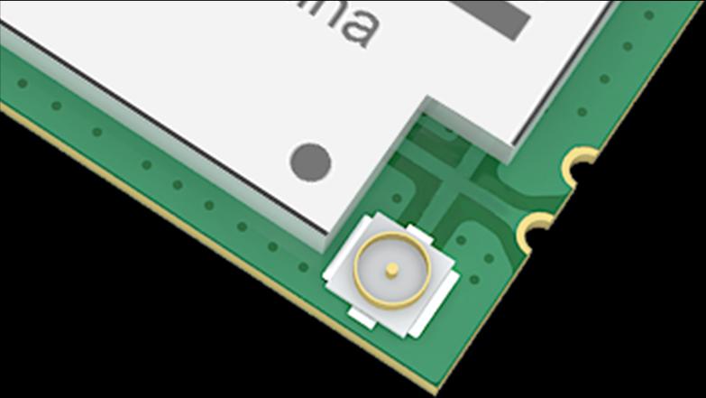
E22-T User Manual
Wrong power register setting, air rate setting is too high (the higher the air rate, the closer the distance);
Low voltage of power supply at room temperature is lower than the recommended value, the lower the voltage the
lower the hair power;
The use of antenna and module matching degree is poor or the antenna itself quality problems.
9.2 Modules are fragile
Please check the power supply to ensure that it is between the recommended supply voltages, if it exceeds the
maximum value it will cause permanent damage to the module;
Please check the power supply stability, the voltage can not be substantial frequent fluctuations;
Please ensure that the installation and use process anti-static operation, high-frequency device electrostatic sensitivity;
Please ensure that the installation and use of the process of humidity should not be too high, part of the components
for humidity-sensitive devices;
If there is no special demand is not recommended to be used at too high or too low a temperature.
9.3 BER is too high
Near the same frequency signal interference, away from the source of interference or modify the frequency and
channel to avoid interference;
Poor power supply may also cause garbled code, be sure to ensure the reliability of the power supply;
Extension cords, feeder cords of poor quality or too long, can also cause high BER.
9.4 Antenna Selection
Enable both the IPEX interface and the stamp hole interface simultaneously. Either the IPEX interface or the stamp hole
interface may be selected as needed.
Copyright ©2012–2026,Chengdu Ebyte Electronic Technology Co.,Ltd. 43
Page 45
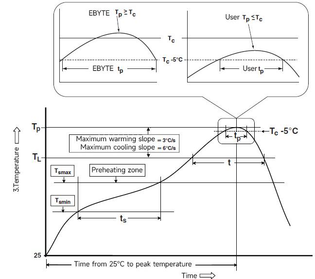
                                                                                   E22-T User Manual


     10 Welding instructions


     10.1 Reflow temperature

                Reflow Soldering Profile Characteristics            Lead-based assembly process        Lead-Free Assembly
                                                                                                              Process
                               Minimum Temperature (Tsmin)                      100℃                           150℃
      Preheat/Keep Warm        Maximum Temperature (Tsmax)                      150℃                           200℃
                                    Time (Tsmin~Tsmin)                         60-120S                        60-120S
                     Temperature Rise Rate (TL~Tp)                     3°C/s, maximum value           3°C/s, maximum value
                     Liquid Phase Temperature (TL)                              183℃                           217℃
                         Hold Time Above TL                                    60~90S                         60~90S
                                                                    Users must not exceed the       Users must not exceed the
                                                                    temperature indicated on the    temperature indicated on
                      Peak Package Temperature Tp
                                                                    product's           “Moisture   the product's “Moisture
                                                                    Sensitivity” label.             Sensitivity” label.
       Within the specified temperature range (Tc) of 5°C, the
        time (Tp) required to reach the target temperature is                  20s                             30s
                     shown in the figure below.
                 Temperature drop slope (Tp to TL)                   6°C/s, maximum value             6°C/s, maximum value
          Time from room temperature to peak temperature              6 minutes, maximum               8 minutes, maximum
      ※The tolerance for the peak temperature (Tp) of the temperature curve is defined as the user's upper limit.


     10.2 Reflow temperature


Copyright ©2012–2026,Chengdu Ebyte Electronic Technology Co.,Ltd.                                                            44
Page 46
                                                                                         E22-T User Manual


     11 Related Models

                                                                                                   Product
                              Carrier            Transmit               Test       Package                          Communication
         Model No.                                                                                Dimensions
                           frequency Hz         Power dBm           Distance km     Type                              Interface
                                                                                                    (mm)
       E22-400M22S            433/470M                22                 7          SMD             14*20                 SPI
       E22-400M30S            433/470M                30                12          SMD            24*38.5                SPI
       E22-900M22S            868/915M                22                 7          SMD             14*20                 SPI
       E22-900M30S            868/915M                30                12          SMD            24*38.5                SPI


     12 Antenna Guide


     12.1 Antenna Recommendations

           Antennas play a crucial role in communication processes, and substandard antennas can significantly impact
     communication systems. Therefore, our company recommends certain antennas that are compatible with our wireless
     modules, offering superior performance at a reasonable price.
                                            Frequenc
                                                     Interfa                      Height      Feed line
           Model No.             Type        y Band          Gain (dBi)                                             Features
                                                       ce                         (mm)          (cm)
                                              (Hz)
                               Rubber
                                                                                                               Ultra-short straight,
         TX433-JZG-6            Rod            433M        SMA-J        2.5        62             -
                                                                                                             omnidirectional antenna
                               Antenna
                               Rubber
                                                                                                              Bendable plastic rod,
         TX433-JW-5             Rod            433M        SMA-J        2.0        50             -
                                                                                                             omnidirectional antenna
                               Antenna
                               Rubber
                                                                                                              Bendable plastic rod,
        TX433-JWG-7             Rod            433M        SMA-J        2.5        75             -
                                                                                                             omnidirectional antenna
                               Antenna
                               Rubber
                                                                                                              Bendable plastic rod,
         TX433-JK-11            Rod            433M        SMA-J        2.5        110            -
                                                                                                             omnidirectional antenna
                               Antenna
                               Suction
                                                                                                              Compact suction cup
       TX433-XPL-100            Cup            433M        SMA-J        3.5        185          100
                                                                                                             antenna, cost-effective
                               Antenna
                               Suction
                                                                                                               Neutral suction cup
        TX433-XP-200            Cup            433M        SMA-J        4.0        190          200
                                                                                                                antenna, low loss
                               Antenna
                               Suction
                                                                                                               Large suction cup
       TX433-XPH-300            Cup            433M        SMA-J        6.0        965          300
                                                                                                               antenna, high gain
                               Antenna
                                Rubber                                                                         Ultra-short straight,
          TX490-JZ-5                        470/490M SMA-J              2.0        50             -
                                 Rod                                                                         omnidirectional antenna

Copyright ©2012–2026,Chengdu Ebyte Electronic Technology Co.,Ltd.                                                                    45
Page 47
                                                                                 E22-T User Manual
                                            Frequenc
                                                     Interfa              Height      Feed line
           Model No.             Type        y Band          Gain (dBi)                                    Features
                                                       ce                 (mm)          (cm)
                                              (Hz)
                               Suction
                                                                                                      Compact suction cup
       TX490-XPL-100            Cup         470/490M SMA-J          3.5    120          100
                                                                                                     antenna, cost-effective
                               Antenna
                               Rubber
                                                                                                     Flexible rod antenna,
      TX868-JKS-IPX20           Rod            868M       IPEX-1    3.0    197          200
                                                                                                        omnidirectional
                               Antenna
                               Rubber
                                                                                                     Flexible rod antenna,
       TX868-JZLW-15            Rod            868M       IPEX-1    3.0    165          150
                                                                                                        omnidirectional
                               Antenna
                               Suction
                                                                                                      Compact suction cup
       TX868-XPL-100            Cup            868M       SMA-J     3.5    290          100
                                                                                                     antenna, cost-effective
                               Antenna
                               Rubber
                                                                                                     Flexible rod antenna,
        TX868-JKD-20            Rod            868M       SMA-J     3.0    170            -
                                                                                                        omnidirectional
                               Antenna
                               Rubber
                                                                                                     Flexible rod antenna,
      TX915-JKS-IPX20           Rod            915M       IPEX-1    3.0    197          200
                                                                                                        omnidirectional
                               Antenna
                               Rubber
                                                                                                     Flexible rod antenna,
       TX915-JZLW-15            Rod            915M       IPEX-1    3.0    155          150
                                                                                                        omnidirectional
                               Antenna
                               Rubber
                                                                                                     Flexible rod antenna,
        TX915-JKD-20            Rod            915M       SMA-J     3.5    200            -
                                                                                                        omnidirectional
                               Antenna
                               Suction
                                                                                                      Compact suction cup
       TX915-XPL-100            Cup            915M       SMA-J     3.5    260          100
                                                                                                     antenna, cost-effective
                               Antenna


Copyright ©2012–2026,Chengdu Ebyte Electronic Technology Co.,Ltd.                                                            46
Page 48
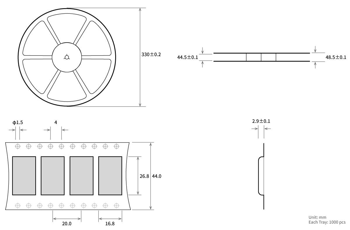
                                                                    E22-T User Manual


     13 Bulk packaging method


     13.1 E22-230/400/900T22S Bulk Packaging Method


Copyright ©2012–2026,Chengdu Ebyte Electronic Technology Co.,Ltd.                       47
Page 49
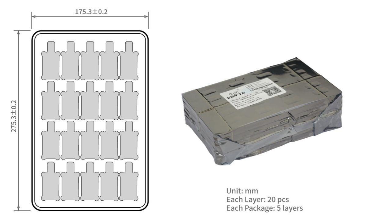
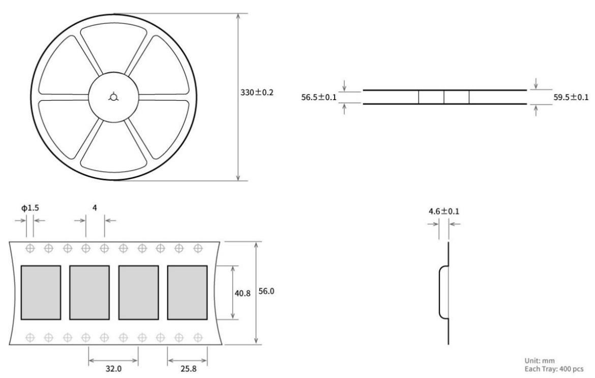
                                                                    E22-T User Manual

     13.2 E22-230/400/900T22D(30D) Bulk Packaging Method


     13.3 E22-230/400/900T30S Bulk Packaging Method


Copyright ©2012–2026,Chengdu Ebyte Electronic Technology Co.,Ltd.                       48
Page 50

                                                                                                  E22-T User Manual


     Revision history

          Version                 Revision Date                                Revision Notes                         Maintainer
            1.0                    2023-10-25                                   Initial Version                          Hao
            1.1                     2024-3-20                                Content Corrections                         Hao
            1.2                     2024-3-29                                Content Corrections                         Hao
            1.3                     2024-6-21                               Content Format Updates                       Hao
                                                                 Updated Surface Mount Component Dimension
             1.4                     2025-2-13                                                                           Hao
                                                                                  Drawings
             1.5                    2025-10-27                    Model Consolidation and Content Integration            Hao
             1.6                     2026-2-5                      WOR instruction description modification              Hao
             1.7                     2026-3-16                    Airspeed Command Modification Description              Hao
             1.8                     2026-5-29                               Content Corrections                         Hao
             1.9                     2026-9-2                                Content Corrections                         Hao


     About us

     Technical support: support@cdebyte.com
     Documents and RF Setting download link: https://www.cdebyte.com
     Thank you for using Ebyte products! Please contact us with any questions or suggestions: info@cdebyte.com
     ------------------------------------------------------------------------------------------------------------
     Web: https://www.cdebyte.com
     Address: B5 Mould Industrial Park, 199# Xiqu Ave, High tech Zone, Chengdu, Sichuan, China


Copyright ©2012–2026,Chengdu Ebyte Electronic Technology Co.,Ltd.                                                                  49
Figures and diagrams from the PDF
Preview the extracted datasheet assets and open any image in a separate tab for closer inspection.
Use this datasheet from any agent
Send the page, markdown, chunks, or search endpoint to ChatGPT, Claude, embedr-app, or your own tooling.